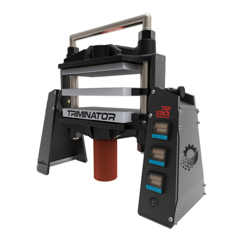
Triminator Rosin TRP stack User manual

®
RosinTRPstack
OWNER'S MANUAL
V 1.4

CONTENTS
INTRODUCTION............................................................... 2
SAFETY MESSAGES ....................................................2
ROSIN PRESS SAFETY ................................................... 3
IMPORTANT SAFETY INFORMATION .........................3
SAFETY LABEL LOCATIONS........................................... 4
CONTROLS AND COMPONENTS.................................... 5
STARTING THE ROSIN PRESS ....................................... 7
ROSIN PRESS OPERATION ............................................ 8
PID TROUBLESHOOTING................................................ 9
LIMITED WARRANTY...................................................13
EXCLUSIONS FROM WARRANTY COVERAGE ...........14
CUSTOMER SERVICE................................................ 14

INTRODUCTION
Congratulations on your selection of the Triminator Rosin TRP Stack! We want to help you to get
the best results from your new press and to operate it safely. This manual contains the informa-
tion on how to do that; please read it carefully before you set up and use your rosin press.
We suggest you read the LIMITED WARRANTY (page 13) to fully understand coverage and your
responsiilities of ownership. Keep this owner’s manual handy, so you can refer to it at any time.
This owner’s manual is considered a permanent part of the rosin press and should remain with
the press if resold. The information and specifications included in this publication are those that
were in eect at the time of approval for printing. Mosman Machinery Company, Inc. reserves
the right, however, to discontinue or change specifications or design at any time without notice
and without incurring any obligation whatsoever. No part of this publication may be reproduced
without written permission.
SAFETY MESSAGES
Your safety and the safety of others are very important. We have provided important safety
messages in this manual and on the Triminator. This information alerts you to potential hazards
that could hurt you or others. Please read these messages carefully. Of course, it is not practical
or possible to warn you about all the hazards associated with operating or maintaining a hydrau-
lic press. You must use your own good judgment.
You will find important safety information in a variety of forms:
Safety Labels - located on the rosin press.
Instructions - how to use this rosin press correctly and safely.
Safety Messages - preceded by a safety alert.
A symbol and one of two signal words: DANGER, CAUTION. These signal words mean:
Each message tells you what the hazard is, what can happen, and what you can do to avoid inju-
ry.
Damage Prevention Messages - You will also see other important messages that are preceded by
the word NOTICE. This word means:
2
DANGER
!CAUTION
You WILL be KILLED or SERIOUSLY HURT
if you don’t follow instructions.
You CAN be KILLED or SERIOUSLY HURT if
you don’t follow instructions.
NOTICE Your rosin press or other property can be dam-
aged if you don’t follow instructions.

ROSIN PRESS SAFETY
IMPORTANT SAFETY INFORMATION
Triminator rosin presses are designed to extract essential elements from plants containing resin
glands utilizing heat and pressure and from a variety of herbal material. Other uses could result
in injury to the operator or damage to the rosin press and or other property. Injuries and prop-
erty damage arising from the use of the Triminator rosin press can be prevented by following
all instructions in this manual and on the rosin press. The most common hazards are discussed
below, along with the best way to protect yourself and others.
OPERATE ON FLAT SURFACE
To avoid overturning, only operate the rosin press on flat, hard, durable surfaces. Preferably at
table height or higher for best access and operator visibility. Press is heavy and must be posi-
tioned on a flat surface so as to prevent any accidental upset or tip-over.
AVOID CONTACT WITH HEAT PLATENS
Heat platens can operate at temperatures up to 225 degrees fahrenheit. Prolonged contact can
cause serious burns. Note red indicator light on power button indicating power ON and platens
hot.
TURN ELECTRIC POWER OFF AND UNPLUG WHEN NOT OPERATING THE ROSIN PRESS
If you need to leave the rosin press for any reason, always turn electric power o.
MANUAL HYDRAULIC PUMP
Do not place fingers or other body parts in area between heat platens when hand pumping hy-
draulic pump. Pinching or crushing injuries could result.
AIR OR ELECTRIC HYDRAULIC POWER OPTIONS
Do not place fingers or other body parts in area between heat platens.
Keep BOTH hands on power unit contols at all times when hydraulicly closing press platens.
All rosin press loading and closing functions are to be activated by a single person operator ONLY.
OPERATOR RESPONSIBILITY
Know how to stop and reverse press action immediately in case of emergency. Understand the
use of all rosin press controls. Never permit anyone to operate the rosin press without proper
instruction. Do not let children operate the rosin press.
3

3
SAFETY LABEL LOCATIONS
4
The labels shown here contain important safety information. Please read them carefully.
These labels are considered a permanent part of your rosin press. If a label comes o or be-
comes hard to read, promptly contact your authorized Triminator dealer for a replacement.

CONTROLS AND COMPONENTS
PID Temperature Gauge
Controls temp for each
platen.
Power Button
Aluminum Platens
6 inch by 10 inch with two
heating elements per plat-
en.
Hydraulic Cylinder
Steel Frame
Cast in NorCal.
Drip Tech Handle
Pull down & up to
operate.
Hose Interface
Connect pump to hy-
draulic cylinder with
hose interface.
Drip Tech Pivot
See graphic at
bottom of page
Drip Tech Pivot
View of machine piv-
oted to allow rosin to
fall below.
5

BEFORE OPERATION
Read and understand this manual. Know what the controls do and how to operate them.
Familiarize yourself with the rosin press and its operation before you begin using it. Know
how to quickly shut o the machine in case of an emergency.
Your safety is your responsibility.
IS YOUR ROSIN PRESS READY FOR OPERATION?
For your safety, and to maximize the service life of your equipment, it is very important to
take a few moments each time before you operate the press to check its condition. Be sure
to take care of any problem you find before you operate the rosin press.
Improperly maintaining this rosin press, or failing to correct a problem before operation,
could cause a malfunction which could cause you to be seriously injured.
Always perform a pre-operation inspection before each operation, and correct any problem.
Before beginning your pre-operation checks, be sure the rosin press is on a level surface,
the power button is in the OFF position, and power cord is unplugged.
CHECK THE GENERAL CONDITION OF THE ROSIN PRESS
Check each control for proper operation.
Check parts for wear. Replace if necessary.
Check that all nuts, bolts, and clamps are tightened appropriately.
OPERATING THE DRIP TECH PIVOT SYSTEM
To operate the Easy Pivot Drip Tech system, pull down the on the Drip Tech handle on the
top of the machine.
CONTROLS AND COMPONENTS (CONT)
65

STARTING THE ROSIN PRESS
7
CONNECT POWER CORD
Connect the Rosin Press power cord to a 20A 120V AC circuit. Optional air or electric power
units may be plugged in to the same outlet. Do not connect and disconnect the power cord
with wet hands. Do not operate in the rain.
NOTICE
Rosin Press machine alone draws approximately 15 amps. With optional electric power
unit, total current draw will be approximately 30 amps.
ATTACH HYDRAULIC PUMP UNIT
Connect hose from manual, air, or electric hydraulic pump to Rosin Press cylinder. Engage
hose fitting by pushing into mating cylinder and turning locking ring to secure.
STARTING THE ROSIN PRESS
Push power putton in. Button will illuminate in red color indicating power on condition.
Heat platens will take up to 15 minutes to heat and stabilize at desired temperature. When
starting the rosin press the temperature may overshoot programed temperature before
stabilizing.
STOPPING THE ROSIN PRESS
To turn o Rosin Press, push power button in, release, red light will stop, and power will be
in o mode.
DISCONNECT POWER CORDS
Unplug Rosin Press cord from power outlet. Unplug optional air or electric hydraulic power
unit from AC outlet.
COOL DOWN
Allow sucient time in power o mode for Rosin Press to cool before attempting to move
machine.
NOTICE: Be sure to hold the plug when disconnecting the power cord from the electrical
outlet. Do not disconnect by pulling on the power cord.

7
ROSIN PRESS OPERATION
8
Program optimal press platen temperature into temperaure control (PID) units. Typically
press operation will be between 195 to 220 degrees fahrenheit.
To adjust set value temperature on PID control push and hold up arrow button for three
seconds.
Wait at least 15 minutes after Rosin Press starts for press platens to reach desired and
stable temperature. Note that some slight fluctuation is normal.
Insert prefilled filter bag packet(s) and PTFE catchment paper between press platens. To
optimze press performance, position bags close to center of press platen surface. Multiple
small bags may be used.
Close press platens by activating hydraulic pump, either by hand unit or with power pump
options. Pressure gauge on pump will read approximately 500 psi. Wait until liquid can be
seen forming along packet edges, then slowly increase pump pressure to 7000 psi. Com-
bination of heat and intense prssure will push out all liquid rosin material from filter bag
packets.
Maximum recommended pressure as viewed on pump gauge is 7000 psi.. Approximately
20 Tons at press platens.
When all rosin has been extracted, release pump pressure. Platens will return to open posi-
tion. Remove spent filter bag packet and catchment paper, reload with fresh material, and
repeat press operation.
When filter bag packet and catchment paper have cooled suciently, dried rosin material
may be removed.
Increase temperature
Press and hold the up button for 3 seconds. At desired
temp, press the set button.
Decrease temperature
Hold the up arrow for 3 seconds. Then, press the down
arrow until the desired temp is shown. Press the set
button.
Check current temperature setting
Press the up button and the set temp will show. Press
the set button, and the current temp will show again.

PID TROUBLESHOOTING
Your press has a PID controller on it, it has a temperature sensor and two heating cartridg-
es per platen. These elements communicate with each other in a permanent closed loop
controlled by a microcomputer.
Your PIDs come preset with standard operational parameters however some users may
want to adjust or fine tune the PIDs further. For this reason we have included the following
guide for advanced troubleshooting.
PID Standard Operational Parameters
The below graphic shows the pre-set advanced settings menu and general setting menu on
the Rosin TRP Stack.
9

PID TROUBLESHOOTING (CONT)
Troubleshooting the PID
If you find a platen or platens are not functioning properly, you may wish to reset the PID.
Some of the most common issues people may have are below.
Press Doesn’t Reach the Preset Temperature
A press that doesn’t reach the preset temperature usually has the PID parameters set up
incorrectly. Verify “standard operational parameters” on page 9. Go through all the settings
and verify that they match. If they don’t match, write down the current PID parameters. To
reset parameters, follow steps on page 11 & 12.
Temperature Gun Shows a Dierent Temperature
Temperature guns can be highly inaccurate when reading temperatures in reflective surfac-
es or at an angle. We suggest an actual thermometer and some kind of lubricant between
the tip of the reader and the specific surface area for which you want to read the tempera-
ture.
If you want to use a temperature gun, you should paint a black spot on the surface of the
platen with some kind of permanent marker, and take the reading as close as possible to
that spot, and perpendicular to the surface.
When it’s determined that a reset is necessary, the following is a guide showing how to
properly reset a single PID. You will need to repeat the steps for each PID that needs to be
reset.
10

PID TROUBLESHOOTING (CONT)
Unlock General Settings PID Menu 1
»Push SET button and hold for 3 seconds.
»Push SET button to advance through settings until you get to the screen Loc.
»Push UP to increase number or DOWN arrow to decrease number until you get to
the number 0, then push SET button again until you get to the main screen or allow
the screen to timeout to return to the main screen.
Unlock General Settings PID Menu 2
»Push SET button and UP arrow and hold for 3 seconds.
»Push SET button to advance through settings until you get to the screen Loc.
»Push UP to increase number or DOWN arrow to decrease number until you get to
the number 0, then push SET button again until you get to the main screen or allow
the screen to timeout to return to the main screen.
Now the PID is unlocked and the parameters can be reset.
Reset the General Settings PID Parameters to Default Values Menu 1
The following settings have been optimized by Triminator engineers to provide the best
platen performance. Refer to the PID Manufacturing Settings graph. Follow these settings
exactly.
»Push SET button and hold for 3 seconds.
»Push SET button to advance through settings.
»Push UP to increase number or DOWN arrow to decrease number until you get to
the desired value. Enter the setting based on the numbers provided in the PID Man-
ufacturing Settings graph.
»Push SET button again and continue setting all the values.
For P, I, D, the settings are dependent on top, middle or bottom platen.
Use chart numbers shown in the graphic below to set the platens.
11
»Once all values have been set, push SET button
again until you get to the main screen or allow
the screen to timeout to return to the main
screen.

PID TROUBLESHOOTING (CONT)
Once you have your PID parameters set. Lock your PID Menu to prevent any changes.
Relock General Settings PID Menu 1
»Push SET button and hold for 3 seconds.
»Push SET button to advance through settings until you get to the screen Loc.
»Push UP to increase number or DOWN arrow to decrease number until you get to
the number 1, then push SET button again until you get to the main screen or allow
the screen to timeout to return to the main screen.
Relock General Settings PID Menu 2
»Push SET button and UP arrow and hold for 3 seconds.
»Push SET button to advance through settings until you get to the screen Loc.
»Push UP to increase number or DOWN arrow to decrease number until you get to
the number 0, then push SET button again until you get to the main screen or allow
the screen to timeout to return to the main screen.
Now the parameters are locked which will prevent any accidental changes.
Setting Maximum Platen Temperature
If you prefer to set a maximum platen temperature, you’ll need to unlock the General Set-
tings PID Menu 1 and 2 before following the steps below.
»Push SET button and UP arrow and hold for 3 seconds.
»Push SET button to advance through settings until you get to the screen d1H.
»Push UP to increase number or DOWN arrow to decrease number until you get to
the maximum temperature, then push SET button again until you get to the main
screen or allow the screen to timeout to return to the main screen.
12

LIMITED WARRANTY
13
TRIMINATOR EQUIPMENT
This warranty is limited to the Triminator Machine distributed by Mosman Machinery Com-
pany, Inc., Nevada City, California 95959. The following warranty applies to all Triminator
products purchased directly or from retail outlets after January 1, 2013.
LENGTH OF WARRANTY
All Triminator products are covered under this warranty for a length of 24 months from the
date of original purchase.
TO QUALIFY FOR THIS WARRANTY:
The product must be purchased in the United States, directly from Mosman Machinery
Company, Inc. or from a dealer authorized by Mosman Machinery Company, Inc. to sell
those products. This warranty applies to the first retail purchaser during the applicable
warranty time period.
WHAT WILL BE REPAIRED OR REPLACED UNDER WARRANTY:
Mosman Machinery Company, Inc. will repair or replace, at its option, any part that is
proven to be defective in material or workmanship under normal use and proper mainte-
nance as prescribed in this Manual during the applicable warranty time period. Warranty
repairs and replacements will be made without charge for parts or labor. Any part replaced
under warranty becomes the property of Mosman Machinery Company, Inc. All new parts
replaced under warranty will be considered as part of the original product, and any warranty
on those parts will expire coincident with the original product warranty.
TO OBTAIN WARRANTY SERVICE:
You must call Triminator/Mosman Machinery Company, Inc. to discuss the warranty issue.
Phone: 530.265.4277
Following the qualifying phone conversation Mosman Machinery Company, Inc. may direct
you to do one of the following:
At your expense, take the Triminator product, part to be replaced, or the equipment on
which the part to be replaced is installed, and a proof of purchase to the Triminator deal-
er from whom you originally purchased the product, during the dealer’s normal business
hours.
Alternatively, Mosman Machinery Company, Inc. may direct you in writing (email) to deliver
your product to a dierent location at a distance less than or equal to the distance from
your current location to the dealer from which you originally purchased the product.

LIMITED WARRANTY (CONT)
14
EXCLUSIONS FROM WARRANTY COVERAGE
The following items and conditions are excluded from warranty coverage:
Any damage or deterioration resulting from the following:
»Neglect of the periodic maintenance as specified in this manual.
»Improper repair or maintenance.
»The use of non-genuine Triminator parts and/or products other than those approved
by Mosman Machinery Company, Inc.
»Exposure of the product to chemical agents, sea water, sea breeze, salt or other
damaging environmental phenomena.
»Collision, deterioration, neglect, unauthorized alteration, misuse, incorporation or
use of unsuitable attachments, products or parts.
»Natural wear and tear (natural fading of painted or plated surfaces, sheet peeling
and other natural deterioration).
Consumable parts: Mosman Machinery Company, Inc. does not warrant parts that deterio-
rate due to natural wear and tear.
Cleaning, adjustment, and normal periodic maintenance work (lubrication, blade sharpen-
ing, belt adjustments).
Any product that has ever been declared a total loss or sold for salvage by a financial insti-
tution or insurer.
DISCLAIMER OF CONSEQUENTIAL DAMAGE AND LIMITATION OF IMPLIED
WARRANTIES:
Mosman Machinery Company, Inc. disclaims any responsibility for loss of time or use of the
product, transportation costs, commercial loss, or any other incidental or consequential
damage. Any implied warranties are limited to the duration of this written limited warran-
ty. This warranty gives you specific legal rights, and you may also have other rights which
vary from state to state.
CUSTOMER SERVICE
For all customer service inquiries or to help you diagnose any issues with your machine
contact Triminator directly:
Phone: 530.265.4277
Email: support@thetriminator.com
Web: www.theTriminator.com

Table of contents
Other Triminator Power Tools manuals
Popular Power Tools manuals by other brands

Bosch
Bosch GDR 10,8-LI Professional Original instructions

Ingersoll-Rand
Ingersoll-Rand LA428-EU Product information
Dynapac
Dynapac LH800 operation & maintenance
Staubli
Staubli M-PZ-T2600 operating instructions

Garden Gear
Garden Gear D2939 instruction manual

Chicago Electric
Chicago Electric 67632 Set up and operating instructions
