Trimm Technologies UR8J2-4 Series User manual

Part Number 8519184-0000 Rev: B
Installation Guide
for
UltraRAIDFamily
UR8J2-4xxx – Ultra Rack
SCSI-3 Ultra 2 (Low Voltage Differential – LVD)
UT8J2-4xxx – Ultra Tower
SCSI-3 Ultra 2 (Low Voltage Differential – LVD)

Part Number 8519184-0000 Rev: B

Page iPart Number 8519184-0000 Rev: B
Table of Contents: UltraRAID Family
Text:
Description Page
General Information: ………………………………………………………......1
Description: …………………………………………………………………......1
First – Unpack, Inspect and Check: ……………………………………….......1
Specifications: ………………………………………………………………......2
Dimensions: ………………………………………………………………......2
Power Supply: ……………………………………………………………......2
Cooling: …………………………………………………………………........2
Environment: …………………………………………………………….......2
Drive Type(s) Supported: ………………………………………………..…......3
Host Connection(s): ………………………………………………………….....3
Convert 2 x 4 Configuration to a 1 x 8 or vice versa: ..................................4
Installation Sequence: ……………………………………………………….....5
Mount Enclosure into Rack: ……………………………………………......5
Install Feet (Tower Enclosure only) ……………………………………......5
Install/Remove End Caps (Rack-mount Enclosure only) ……………........6
Drives into Canister: …………………………………………………….......6
Canister into Enclosure: ………………………………………………….....7
Power Supply Install/Remove: …………………………………………...........7
Fan (Auxiliary Blower) Install/Remove: ………………………………...........8
Electronic Circuit Boards: ………………………………………………..........8
Field Replacement Units (FRU’s): …………………………………………...10
Certifications, Cautions and Warranty: …………………………………......12
Certifications: ……………………………………………………………....12
Cautions: …………………………………………………………………....12
Warranty: …………………………………………………………………..13
Technical Support: …………………………………………………………....14
Figures:
Figure 1 Connection Illustration ………………………………….............4
Figure 2 Tower Enclosure Feet …………………………..……………….5
Figure 3 End Cap Install/Remove Illustration .………………………….6
Figure 4 Rear View …………..……………….............................................8
Figure 5 Saf-Te Daughter Board Option Connected to Alarm Board.....9

Page 1of 14 Part Number 8519184-0000 Rev: B
General Information
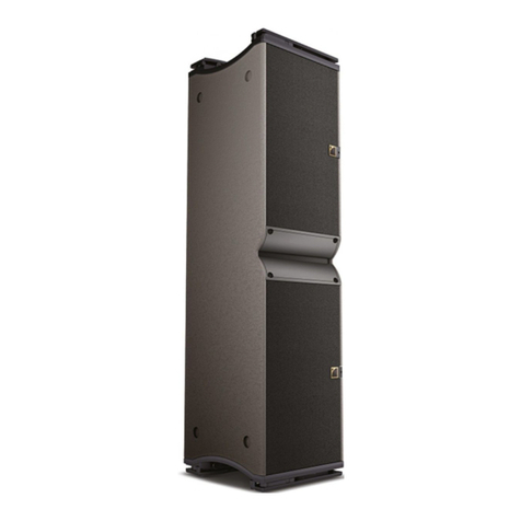
Congratulations on your choice of a Trimm Technologies Enclosure. The UR8J series of enclosures are
intended for rack-mounted applications. The UT8J series of enclosures are tower types for desktop
(deskside) applications. Both types of enclosures support up to eight (8) 3.5” SCSI hard drives. The drives
are to be mounted in drive canisters (modules), which accommodate standard or low profile SCA-2 style
drives. The enclosure provides power and cooling for up to eight drives of the 10,000 RPM class of hard
drives. The canister has been designed to accommodate the rotational characteristics of the 10,000 RPM
category of drives, while providing for fully seating the drive’s connector into the enclosure’s backplane.
Description
The enclosure (chassis) has been designed for Field Replaceable Units (FRU’s) to be interchangeable
between the different units within the family. The enclosure is a midplane (backplane) design with dual
redundant (N+1), hot pluggable power supplies and redundant (N+1) cooling. Likewise, the drive
canisters are hot-pluggable, plugging in from the front of the enclosure.
While the design has a mid-plane, no active components are on the mid-plane. All active components are
on/in pluggable FRU’s, which are accessible either from the front or rear of the enclosure. The N+1
design, along with the pluggable FRU’s provides for maximum uptime.
The drives, accommodated by this family of enclosures, are those that conform to SCSI-3 specifications
with SCA-2 connections. The single-ended and host only low-voltage differential (LVD) versions support
drives up through SCSI-3 Fast 20 (Ultra) for transfer rates up to 40 MB/s, while the LVD native (Host
and Drive) supports SCSI-3 Ultra 2 transfer rates up to 80 MB/s.
The drives must meet the SCSI specifications for bus loading to work properly in an Ultra SCSI
environment. The drive must mechanically comply with the Small Form Factor (SFF) committee (SCSI
working committee) dimensional specifications for SCA drives (or in the alternate, Seagate dimensional
specifications for SCA drives).
Each drive is mounted into a canister (module) and is attached from the bottom. The drive is mounted in
the canister such that the drive connector is fully seated in the midplane (backplane) when the canister
handle is closed and latched into the enclosure. Noting that the drive canister is hot-pluggable, the drive is
not spun down prior to unplugging. To remove a drive, the canister handle is opened (released) from its
latch. Opening the handle on the canister disengages the drive’s connector from the enclosure’s
connector, thereby removing power from the drive, which will then permit the drive to spin down. The
person removing the drive should wait at least ten (10) seconds after opening the handle, for the drive to
spin down, before removing the canister from the enclosure.
First - Unpack, Inspect and Check:
Unpack the enclosure and visually inspect it for damage that may have occurred during shipment. Retain
the shipping carton in case reshipment is necessary.
Check your Drive Manual for inspection, installation and setup information.

Page 2of 14 Part Number 8519184-0000 Rev: B
Specifications:
Dimensions:
Enclosure: (external dim.) (Rack Style) (Tower Style)
Height: 5.25” 13.34cm 20.0”50.80cm
Width: (w/foot) N/A N/A 12.05” 30.61cm
Width: (w/o foot) 19.0” 48.26cm 7.0” 17.78cm
Depth: 22.0” 55.88cm 24.0 60.96cm
Drive Canister (Module):(Internal dim.)
Height: 1.65” 4.19cm (max to permit airflow)
Width: 4.03” 10.24cm
Depth: 7.62” 19.35cm
Weight: (Canisters) 1.7 lbs. 0.77 kg
(Rack Style) Approx. 45.4 lbs. 20.64 kg
(Tower Style) Approx. 65.0 lbs. 29.55 kg
(Rack) Total with eight canisters and no drives = 59.0 lbs. 26.82 kg
(Tower) Total with eight canisters and no drives = 79.0 lbs. 35.91 kg
Power Supply: 350 watt (dual redundant, hot-pluggable)
A/C: 100 – 240 VAC auto-ranging, 50 - 60 Hz
D/C: +5 VDC @ 25 A
+12 VDC @ 25 A
Note: each supply output capable of 25 A,
however, total output power not to exceed 350 watts
Cooling: Three blower fans
Provides for N+1, with a blower in each Power Supply, plus a separate blower
Air-flow – front to rear
Environment:
Temperature:
Operating: 0ºC to 25ºC
Storage: -20ºC to 85ºC
Humidity:
Operating: 0 – 95% non-condensing
Storage: 0 – 95% non-condensing
Altitude:
Operating: 0 – 10,000 feet
Storage: 0 – 40,000 feet

Page 3of 14 Part Number 8519184-0000 Rev: B
Drive Type(s) Supported:
•3.5” full-size (1.65” H) and low profile (LP) (1.00” H) (25mm).
•Hard drive rotational speeds up to 10,000 RPM.
•Using a Single Connect Attach (SCA-2) type connector (80pin).
•Low Voltage Differential (LVD) interface, with transfer abilities up to SCSI-3 Ultra
2, at 40 Mhz for data transfer rates up to 80 MB/s (wide interface). also supported are
Single-Ended drives, however, while Ultra 2 permits a mix of LVD and Single-
ended, as soon as one single-ended device is connected into the SCSI bus, ALL of the
transfer rates and cable distances revert to the lowest common denominator, the
single-ended specifications.
•Drives conforming to the Industry Standard Small Form Factor (SFF) committee
specifications for size and mounting criteria.
Host Connection(s) (Reference Figure 1)
Provides two separate host channels. The host connection is via HD68 type connectors, with each channel
daisy-chaining through four (4) drives in the enclosure, then out to the second connector at the
rear of the enclosure. This second connector must be terminated or daisy-chained to a point that is
terminated.
The enclosure contains two channels of four (4) drives. To set up a configuration of 1 channel of
8 drives or 2 channels of 4 drives, see “Convert 2 x 4 Configuration to a 1 x 8 or vice versa”.
The host connections, are identified as SCSI A and SCSI B. SCSI A is on the right side (rack) or top
(tower), (rear view), with SCSI B on the left side (rack) or bottom (tower), (rear view). Viewing
the enclosure from the front, SCSI A connects to the four (4) drives starting from the left side of
the enclosure. SCSI B connects to the four (4) drives starting with drive bay number five (5),
counting from the left.
The drive addresses are established based on a base address that is set via the Base Address Switch for
each channel. The switches are located at the rear of the unit. SCSI A base address switch sets the
base address for the drive in the bay at the far left (rack) or top (tower), (viewing from the front),
with the next three (3) bays having addresses that are incremented by one for each bay. SCSI B
base address switch sets the base address for the 5th drive bay, counting from the left (top), with
each subsequent bay incrementing by one. SCSI B base address sets the base address for these
drives, even if the interface has been jumpered for a one channel by eight drive configuration.
(NOTE: when setting drive addresses, the host address is normally set to 7).
(NOTE: the drive address switches control their respective bank of drives regardless of the
interface configuration, such as a 1 x 8 or 2 x 4 configuration.

Page 4of 14 Part Number 8519184-0000 Rev: B
Figure 1
Connection Illustration
Convert 2 x 4 Configuration to a 1 x 8 or vice versa:
To convert either way, either connect or disconnect a jumper cable between the 2nd connector for
the SCSI A and SCSI B connectors at the rear of the enclosure (reference Figure’s 1and 4).
For a 1 x 8 configuration, install the a SCSI jumper cable between the second connectors for the
SCSI A and SCSI B connectors. The host is connected to SCSI A, while SCSI B is either
terminated or connected to the next device in the chain (reference Figure’s 1 and 4).
For a 2 x 4 configuration, disconnect the cables between SCSI A and SCSI B connectors and
either terminate the second connector for each of SCSI A and SCSI B, or connect them to the
next device in the chain, with a terminator at the end of the chain.

Page 5of 14 Part Number 8519184-0000 Rev: B
Installation Sequence:
•Unpack & Inspect
•Install Enclosure in Rack (Mount Enclosure) (rack style) / Install Feet (tower style)
•Install End Caps (Rack Style)
•Mount Drives in Canisters (Drive Modules)
•Install Canisters in Enclosure
•Set Base Addresses for each Host Channel (in)
•Connect AC Power
Mount Enclosure into Rack (standard 19” RETMA rack):
The standard enclosure is a fixed mount configuration. Install the Rack-Mount kit supplied with
the enclosure, per the instructions supplied with the kit. Empty the enclosure (remove all canisters
and power supplies), remove the end caps from the front ears (use a screwdriver at the bottom of
the end caps to release the flexible latch), then insert enclosure into the rack and attach the front
ears of the enclosure to the rack. Reinsert power supplies and canisters.
Install Feet (Tower only)
The enclosure is shipped with three feet. Two of the feet have a self-adhesive to permit them to
be attached to the bottom (near the rear – see Figure 2). The other foot, is a stabilizer base, which
provides an anti-tip function to the enclosure. This foot is attached with the two screws included
with the foot (see Figure 2).
Figure 2
Tower Enclosure Feet
Remove protective cover
from the adhesive on the
feet and attach feet in the
area where shown.
Attach stabilizer foot to the base of the
enclosure, near the front, as located by
the mounting holes

Page 6of 14 Part Number 8519184-0000 Rev: B
Install/Remove End Caps (Rack-Mount Enclosure only)
The end caps are dress items, which mount on the rail flanges at the ends of the enclosure. The
caps snap in place with a notch at the bottom of the caps. To snap the caps in place, insert the top
notch in place first and then push the bottom in until the flexible flange at the bottom is captured
in the mating indent.
The notch at the bottom, provides access for a screwdriver (or similar instrument) to be inserted
to lift up on the flexible flange to disengage it from the indent and permit the bottom of the cap to
be pulled forward to remove the cap(s).
Figure 3
End Cap Install/Remove Illustration
Drives into Canisters
Mount the drive via the mounting holes at the bottom of the drive to the canister, which will
position the drive to properly engage the drive connector to the mid-plane board in the enclosure.
Use cautions and hardware as defined by the Drive manual/installation guide.
Drive Mounting Holes
Insert end cap notch in
slot on flange
Push in at
the bottom
of the end
cap to snap
flexible
notch into
slot on
flange
To remove end
caps, insert
screwdriver in
notch at the
bottom and
press up on the
flexible tab
until released,
then pull
forward

Page 7of 14 Part Number 8519184-0000 Rev: B
Canister into Enclosure
Insert the canister with the drive in place in a manner similar to the above illustration. The
canister has slides on the sides to help guide the canister into position, The canister has a lever at
the front which cams the canister into the final closed position. (NOTE: To remove, the front
lever is pulled open, which disconnects the drive power. When the power is removed from the
drive it will then park the heads and spin down. After releasing the front lever, pause for
approximately ten (10) seconds to permit the drive to spin down before completing the removal).
The canister has two (2) light pipes, which carries the drive “Active” (amber/yellow) LED signal
from the midplane to the front of the canister. The red (Drive Fault) is not used.
Power Supply Install/Remove
To remove a power supply (reference Figure 4), turn the power switch “off”, remove the attached
power cord, undo the thumbscrews (two for each supply), then grab handle and pull to the rear.
To install, insert supply into opening in enclosure to point where thumbscrews engage, then
tighten thumbscrews to secure power supply in place, then attach power cord, then turn power
switch “on”. (Note, each supply has a green and a red LED to indicate if supply is good or bad –
green on = good; red on = defective supply, needs to be replaced).
Each power supply assembly also houses a fan, power switch and power connection in addition to
the LEDs. If the fan fails the red LED is activated on the supply, along with the alarm and front
panel LED to indicate a failure. The assembly as shown in Figure 4 is the lowest Field
Replacement Unit (FRU).
In a live system, use CAUTION to remove only the failed supply (the one with the red LED on).
CAUTION, with either supply removed, the air flow is misdirected and the drives will overheat
in a matter of minutes, replace supply as quickly as possible in an operating enclosure.
Light pipes
(LED Outputs)
Lever

Page 8of 14 Part Number 8519184-0000 Rev: B
Figure 4
Rear View
Fan (Auxiliary Blower) Install/Remove
To remove the fan assembly (Reference Figure 4), undo the thumbscrew and pull the assembly to
the rear, by pulling on the thumbscrew. To install, push assembly into place and tighten the
thumbscrew. (Note, the fan assembly has a bi-color LED to indicate whether or not the fan is
okay; green = okay; red = fan is defective and needs replacement).
Electronic Circuit Boards
Within the enclosure, there are three (3) (four if optional Saf-Te is installed) circuit boards:
1. On the left front ear (end cap), there is an enclosure status (front display) board, which has
three (3) bi-color LEDs which indicate the status of the power supplies (top LED), enclosure
fans (middle LED) and temperature (bottom LED) within the enclosure. The temperature
LED is red if the enclosure temperature exceeds 45°C. Green indicates okay operation, while
red indicates a problem with the associated function. This board contains the audible alarm
reset switch. When an alarm is triggered, it can be deactivated by pressing the reset switch.
This board is a FRU.
For access to the Display Board , in the Rack Mount, remove the left End Cap. In the Tower
enclosure, remove the stabilizer foot (2 philips screws), then remove the cover (3 philips
screws at rear and then pull cover to the rear), next, remove the front bezel (4 Torx screws,
requires a T20 Torx bit).
Host ConnectionsBase Address Switches
Fan
Power Supply
Front Display
Board (mounted
on left ear)
Alarm Reset
Switch
LEDs
To remove the end cap, insert a
screwdriver in the notch at the
bottom of the cover to release the
tab, then pull the cap forward

Page 9of 14 Part Number 8519184-0000 Rev: B
2. The mid-plane (backplane) board is located approximately in the middle of the enclosure and
connects the drives to the host connection board. This board is not a FRU and is only repaired
by returning the enclosure to Trimm. Generally, this board does not contain any active
components. However, it does contain LED’s, terminator power diodes and fuses.
3. The alarm board is accessible from the rear of the enclosure. (There are two types; one in the
standard JBOD; and one for the JBOD connected in a castle (UR16R) configuration). (The
second type (UR16R) does not have a Saf-Te option as it uses a different communications
method). To remove, undo the mounting screws and pull the board out, using the metal lip
that is mounted at the rear of the board. This board contains the audible alarm circuit. The
board is a FRU. Generally, any active components that are within the enclosure are mounted
on this board. Also, the optional Saf-Te board is mounted on this board as a daughter board.
IF the optional Saf-Te board is installed, then the alarm board CANNOT be removed
from the rear, until and unless the Saf-Te board is removed.
4. The optional Saf-Te board is connected as a daughter-board to the alarm board via two
headers and is also connected to a drive channel via a separate connector. The Saf-Te board
has provisions for setting the address of the Saf-Te device to either SCSI ID 4 or 5 via an on-
board jumper, using jumper P3 (reference Figure 5). To replace the Saf-Te board requires
removing the top cover from the enclosure. With the top cover removed, lift the Saf-Te board
off of the alarm board (connected via two headers) and remove the cable connector (this
connector off disables the Saf-Te device from communicating on the SCSI bus. This board is
a FRU.
Figure 5
Saf-Te Daughter Board Option Connected to Alarm Board
P3 location for SCSI-ID jumper
OFF = 4
ON = 5
Cable connector connectingSaf-Te
to Drive Channel 1
Connectors, connecting Saf-Te
daughter board to Alarm Board

Page 10 of 14 Part Number 8519184-0000 Rev: B
Field Replaceable Units FRU’s
Description Trimm Part Number
Power Supply, 350W (PFC) 5417240-0100
Power Supply, 350W (non-PFC) 5420009-0100
Drive Canister (2 each), 5417239-002*
Drive Canister (8 each), 5417239-008*
End Caps (pair), 5417418-010*
Alarm Board (standard JBOD) Assembly 5418868-0100
Alarm Board (Castle UR16R JBOD) Assembly 5419533-0000
Saf-Te Board Assembly 5418887-0100
Front Display Board 5417335-0100
Fan Assembly (Auxiliary Blower Fan) 5417241-0100
Where * = color:
1 = Light Grey
4 = Charcoal
5 = Black
6 = Taupe
Power Supply Assembly
350W (PFC)
5417240-0100
Fan Assembly
Auxiliary Blower
5417241-0100
Front Display Board
Part Number 5417335-0100
Drive Canister (Module)
Available in several color schemes and
shipped in groups of 2 or 8
5417239-xxxx
Slides
Lever to install or
remove canister
Light Pipes for
Drive Activity and
Drive Failure
Power Supply Assembly
350W (non-PFC)
5420009-0100
Please
Note the type of Handle to determine which type power supply you
have, as they are not interchangeable

Page 11 of 14 Part Number 8519184-0000 Rev: B
Terminator, SE/LVD Multimode
Part Number 5417847-0100
Cable,
multimode (external)
Part Number 5417823-0100 = 1 foot
Part Number 5417823-0200 = 3 foot
Part Number 5417823-0300 = 10 foot
Part Number 5417823-0400 = 25 foot
Alarm Board Assembly
Part Number 5418868-0100
Saf-Te Option Daughter Board
Part Number 5418887-0100

Page 12 of 14 Part Number 8519184-0000 Rev: B
Certifications, Cautions and Warranty
Certifications:
This enclosure, as a component, has been tested and has passed all safety
requirements. The integrator is responsible for End Product testing and agency
verifications. Do not use the enclosure in any manner other than the intended
use/purpose as advertised by Trimm Technologies. The enclosure meets the
requirements of the following agencies:
- - Underwriters Laboratories, Recognized Component
– - Component conformity with EU Directives
- -Canadian Underwriters Laboratories
Testing for other agencies can be done upon request.
In addition, the enclosure has been designed to meet FCC, Class B emission
requirements. System approval can only be obtained when the enclosure is loaded
with drives. The final step is the integrator’s option, with this task being made easier
due to Trimm’s compliance with agency regulations and attention to anti-emission
construction techniques.
This equipment generates, uses, and may emit radio frequency energy. If not
installed in accordance with the information provided in this manual, it may cause
interference to radio communications. It has been tested and found to comply with
the limits for a Class B computing device pursuant to Subpart J of Part 15 of FCC
Rules, which are designed to provide reasonable protection against such
interference when operated in a commercial environment.
Cautions:
Warnings/Cautions
Watch out for Static while handling/installing drives and/or FRU’s!
Although the enclosure is not sensitive to (Static) Electrostatic Discharge (ESD),
any of the electronic circuits, such as the board providing connection from the
external host connection to the internal drives or the drives themselves, are sensitive
to ESD. Heed the warnings and cautions in your drive manual(s). Take care to avoid
damaging your drive and any of the electronic circuit boards by mishandling.
Ideally, a conductive rubber mat and wrist strap should be used if possible,
whenever you are handling any of the drives or electronic circuit boards.

Page 13 of 14 Part Number 8519184-0000 Rev: B
CAUTION:Disconnect power before servicing.
ATTENTION:Débranchez la puissance avant l'entretien.
The power cord provided may not be suitable for the installation country. It is the
user’s responsibility to insure the power cord satisfies local electrical code.
CAUTION: For continued protection against risk of fire, replace only the same
type and ratings of fuse.
Power supplies must be handled with care. If you need to remove a power supply, be
sure not to subject the components to damage (dropping, stacking, etc.).
Warranty:
Trimm Technologies warrants its range of products to be free from defects in
material and workmanship for a period of ONE YEAR from date of manufacture.
The company makes this warranty only to purchasers who acquired the product
direct from the company, its authorized dealers or reps, or others who are
specifically authorized by the company to sell such products. The company’s sole
obligation and the purchaser’s remedy pursuant to this warranty are limited to
repair or replacement, at the company’s option, F.O.B. the company’s plant, of
products which, when used normally and pursuant to the company’s published
instruction, are proven to be defective within the period stated.
The company makes no warranty to purchasers who acquire products for personal,
family or household purposes. No person, firm or corporation is authorized to
assume for the company any liability in connection with the sale or installation of
company’s products except as stated above. THERE ARE NO OTHER
WARRANTIES, EITHER EXPRESS OR IMPLIED, INCLUDING ANY
WARRANTY OF MERCHANTABILITY OR FITNESS FOR ANY PARTICULAR
PURPOSE. The remedies stated herein are expressly set forth, irrespective of the
theory upon which any claim might be based, including breach of contract,
warranty, negligence, or strict liability of tort. Under no circumstances shall the
company be liable for incidental or consequential damages.

Page 14 of 14 Part Number 8519184-0000 Rev: B
Technical Support
If you have any problems or need advice on future expansion / products contact Trimm Technical Support
via:
US:
Mailing Address:
Trimm Technologies, Inc.
350 Pilot Road
Las Vegas, Nevada 89119
Phone: 702-263-2310
Fax: 702-361-6067
Email: [email protected]
Web Site: http://www.trimm.com
UK:
Trimm Technologies Limited
Millennium Way East
Phoenix Centre
Nottingham, England NG8 6AR
+44 (0) 115-951-9951
+44 (0) 115-951-9985

Part Number 8519184-0000 Rev: B
Trimm Technologies, Inc.
350 Pilot Rd.
Las Vegas, Nevada 89119 USA
Phone: 702-263-2310
Fax 702-260-3443
http://www.trimm.com
Trimm Technologies LTD.
Millennium Way East
Phoenix Centre
Nottingham, England NG8 6AR
Phone: +44 (0) 115-951-9951
Fax: +44 (0) 115-951-9985
This manual suits for next models
1
Table of contents
