Trinabess PowerCube 2.0 DC User manual

PowerCube 2.0 DC
Installation Guide –Australia & New Zealand
Feb 2018
V1.5

2
Contents
•1. System Introduction
•2. Unpacking the products
•3. System Installation Steps
•4. WIFI Monitoring Setup Guide

System Introduction
01
•System Topology
•Power Box DC
•PowerCube 2.0
4
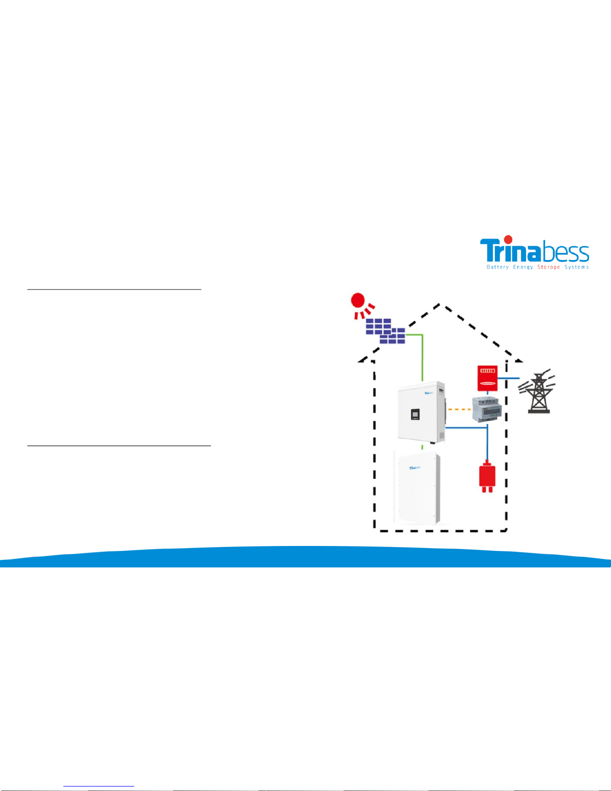
PowerCube System Topology
Power Box (DC – “Hybrid Inverter”):
•DC/AC bi-directional Power Conversion Equipment (PCE)
•Mainly applied and developed for the renewable energy
generation system
•The interface between the grid, solar PV and the battery
storage
•Designed for lithium-ion batteries
PowerCube –Battery Energy Storage:
•Lithium Iron Phosphate (LiFePO4)
•Contain at most 4 battery packs
•Capacity: 4.8kWh –9.6kWh
•Voltage range: 44.5V –54V
5
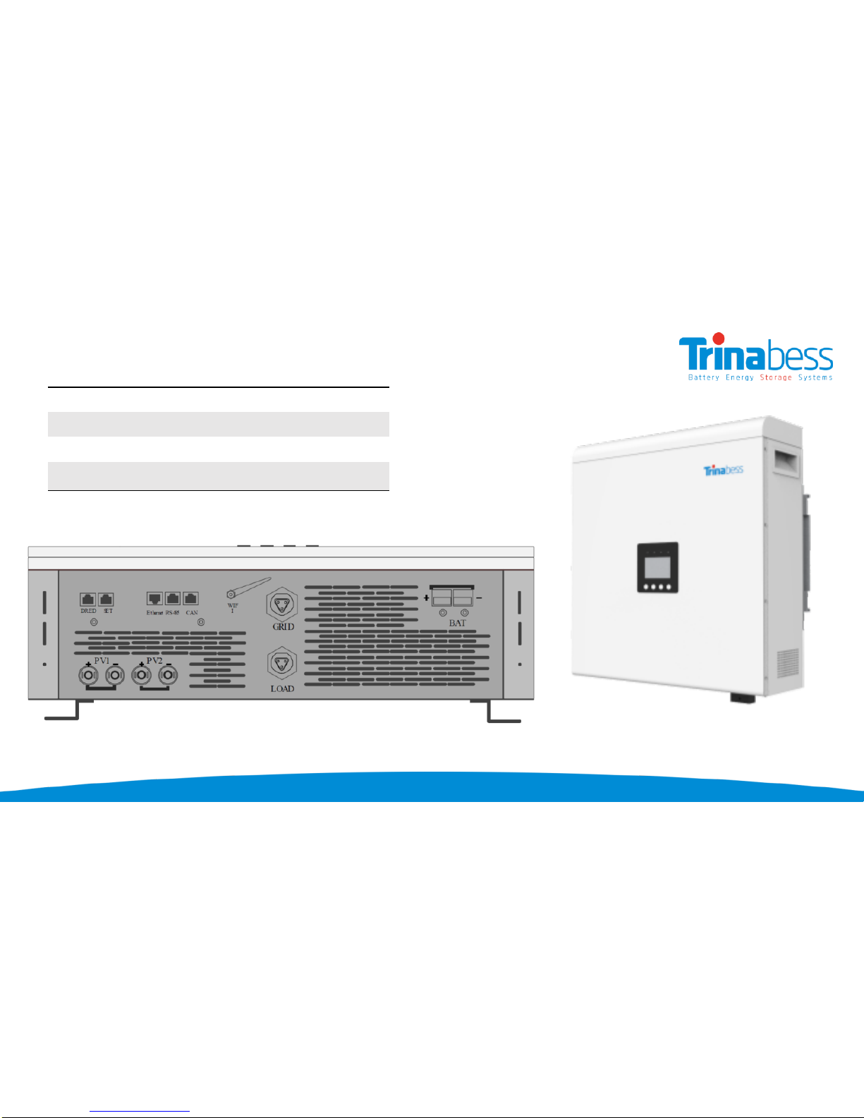
Power Box (DC –Bess Hybrid Inverter)
Length 610mm
Width 515mm
Height 192mm
Weight 30kg

6
PowerCube (Battery Storage)
Advantages:
•The PowerCube and accessories
are designed for simplicity and
convenience
•Can be completed by one
person
•Integrated Isolator design to
reduce the cost and time required
for installation
•Outdoor rating –IP54
Leng
th
100
0mm
W
idth
60
0mm
Height
21
0mm
W
eight
app
.20kG
Leng
th
410
mm
W
idth
4
40mm
Height
88
.5mm
W
eight
25
kg
PowerCube 2.0 Casing: Battery Pack:

Upacking the products
02
•Battery Packs
•PowerCube 2.0 Casing
•Power Box
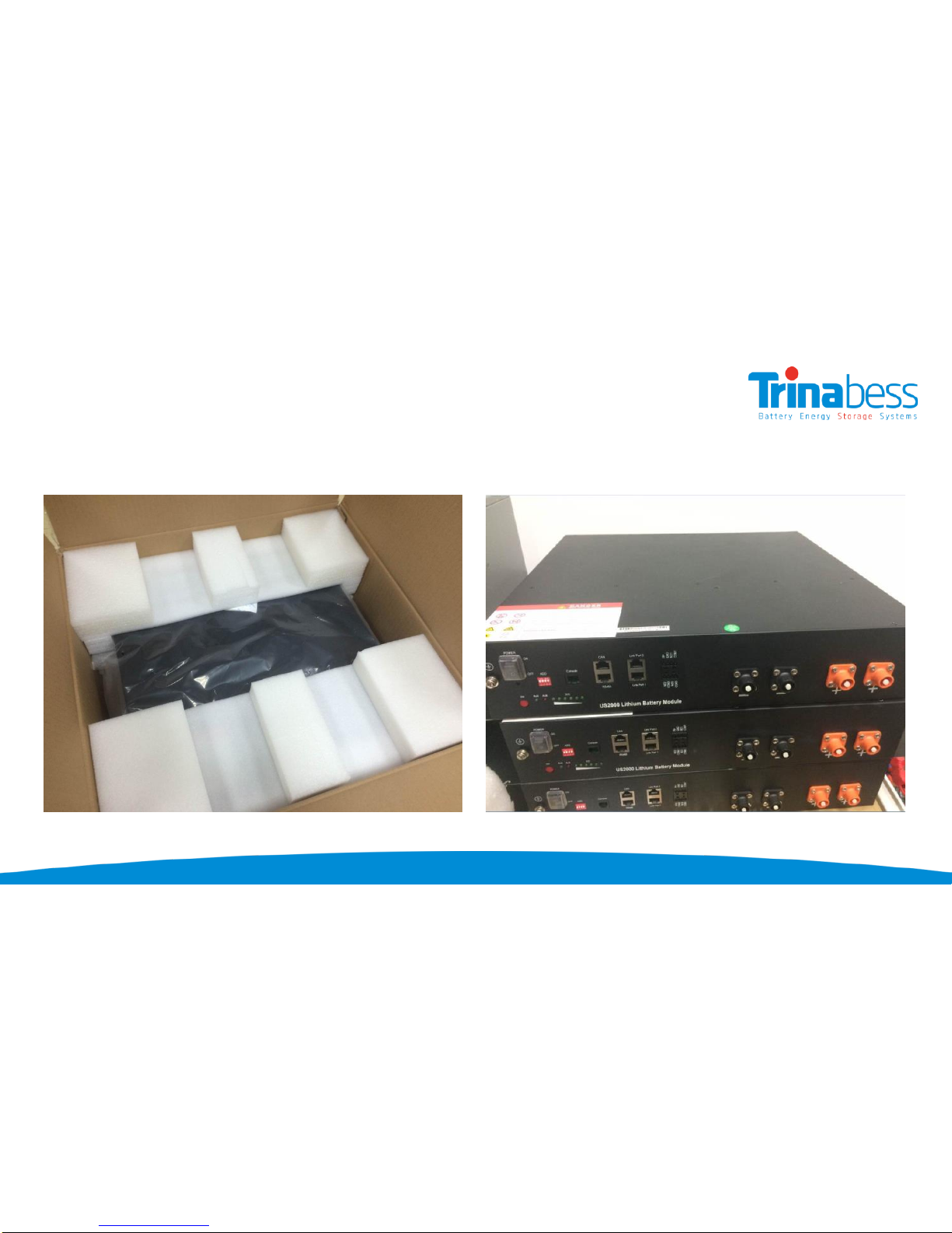
8
Battery Packs
9
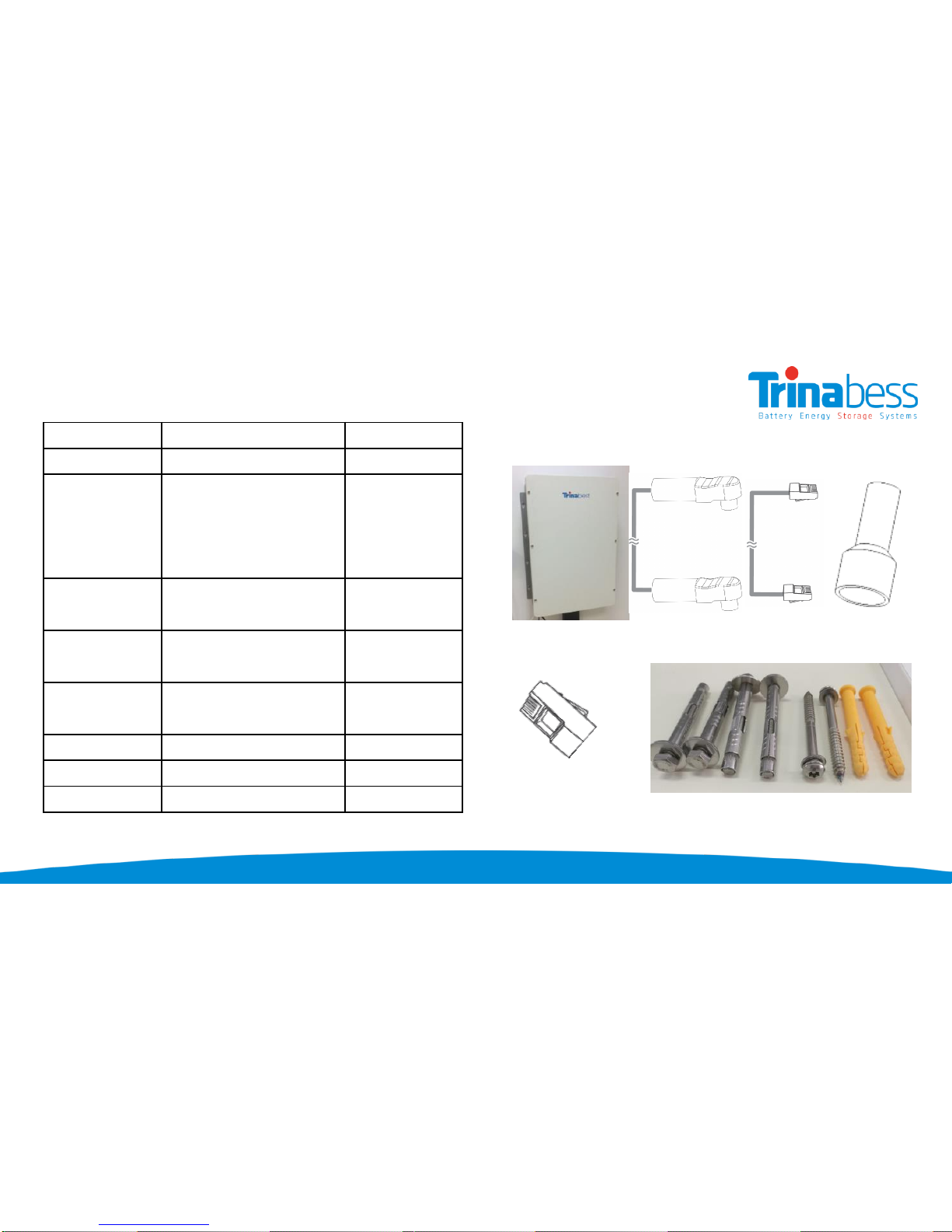
PowerCube
A B C D
E G H F
Component Part Name Quantity
A Casing 1
B
Battery Pack Power
Cable with
connectors
connecting between
battery packs
6
C
RJ45 communication
line with connectors 3
DConnectors without
Power Cable 2
E
RJ45 communication
connectors
2 (1*backup)
F Wall plug 6
G M8 bolt 4
H M8 Anti-Theft bolt 2

10
Power Box DC
Communication Cable & Adapter
Anderson plug & connector (Batt)
Aviation Plug
(Female)
Aviation Plug
(Male)
Plug & Screw Fixings
Solar PV connect (2 pairs)

System Installation Steps
03
•Installation tools and accessories
•Single Line Diagram
•Powerbox installation
•Powercube installation
•BESS installation
•System Initialization
•System Setting

12
Installation Tools
Hammer Drill
Recommend drill dia. 8
& 10mm

13
InstallationAccessories
Depending on the site-specific situation and local electrical compliance requirements, some if not all of
the following parts will be required:
•AC circuit breakers –Minimum four 32A circuit breaker is required next to the BESS system and
inside the main switchboard.Additional ones for extended distance away from
switchboard/distribution board
•AC cables (≥4mm2) –From powerbox to Switchboard/Distribution board & critical loads
•DC cables (≥25mm2)–From powercube to powerbox (2 to 5 metres)
•Ethernet/CAT5 cables –To extend the communication cable, distance between the powercube
and the powerbox. Or to extend the Energy meter communication cables.
•Conduits –20mm
14
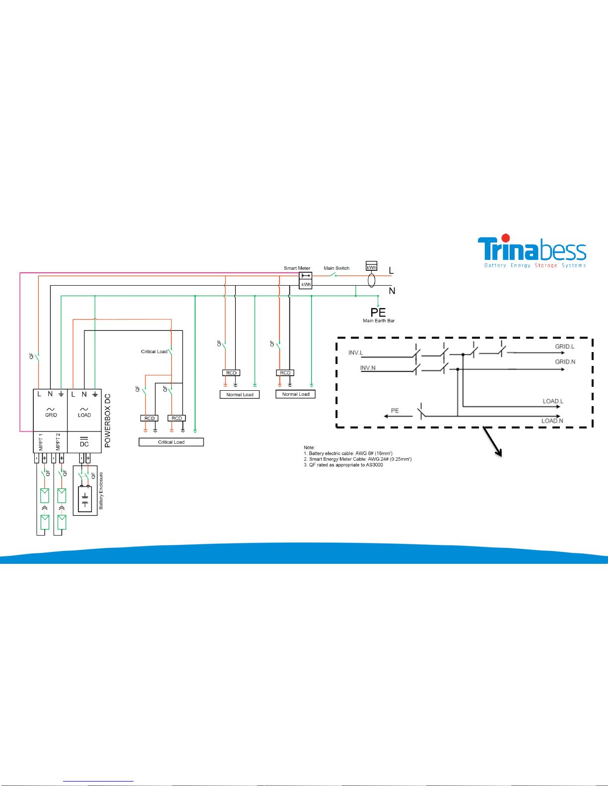
System Connection –Single Line Diagram
TB5200SH internal wiring diagram

15
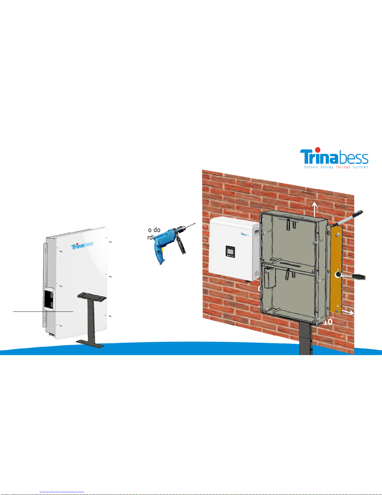
1) Choose a proper position for the mounting bracket
on the wall and mark it
2) Use Φ10 drill template to drill holes on marked
position
3) Fix the expansion bolt into the hole
4) Fix wall bracket on the wall
5) Fix screw through bracket to expansion tube, adjust
the bracket position and screw in
6) Align with wall bracket, move Powerbox DC in
horizontal direction to proper position
7) Make the hook on wall bracket insert into the hole on
the Powerbox DC inverter
8) Slowly lower Inverter, ensure the inverter hang on the
hook of wall bracket
9) Check if Inverter is properly fixed on the wall
Installing the hybrid inverter
≥300mm
≥200mm
≥200mm
≥500mm
16
Powercube installation –PowerCube Mounting
Step 1: Remove the enclosure cover
Step 2: Remove the Circuit Breaker cover
Step 3: Use the cardboard template provided to do
wall-mount hole “marking” and drill holes accordingly
Step 4: Insert wall plug and drive the M8 bolts
Note: Place two anti-theft bolts in the middle hole
Step 5: Hook on the PowerCube enclosure before
securing & tightening the bolts.
Pedestal (Optional):
≥300mm
≥100mm
≥100mm
≥100mm

17
Powercube installation –Battery packs
Once the Powercube enclosure have been secured
with bolts.
Step 1: Insert the packs into the mounted casing
Step 2: Turn the baffle to secure the battery packs
18
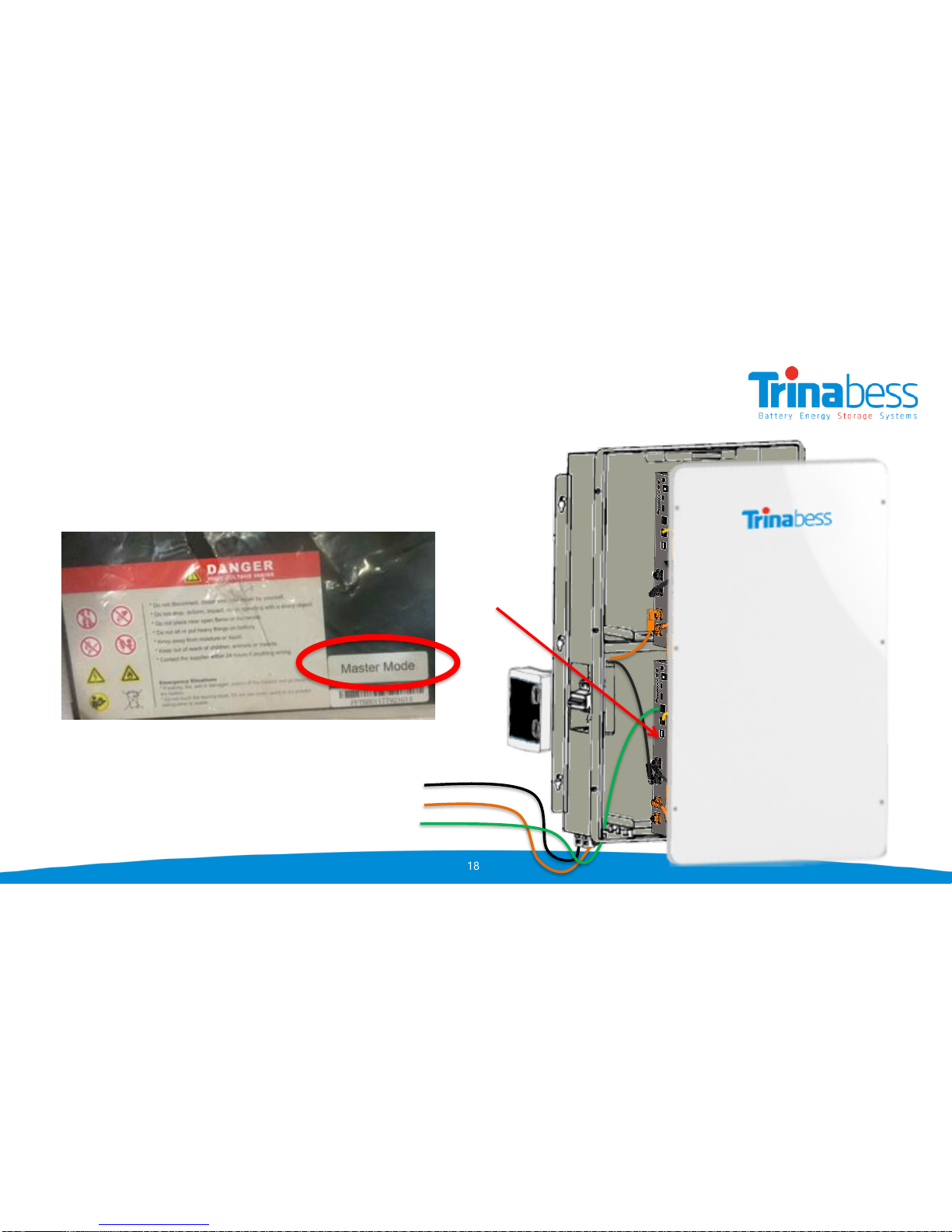
Powercube installation –BESS connections
Connecting the packs together
Step 1: Connect a master pack. The master should have the
breaker Negative cable connected to it. It should also have the
label “Master Mode”
Step 2: Connect rest of the negative cables
Step 3: Connect the positive cables.
Note: for better performance, connect the breaker positive cable to
the last battery pack.
Step 4: Connect the inverter comms cable (to Master only)
Step 5: Connect the comms cable between the battery packs
Step 6: Measure the required distance from powercube to
Powerbox & prepare a positive and negative DC cable and
connect to battery breaker
Slave
Master
Breaker Negative cable
Inverter comms cable
Breaker Positive cable
19
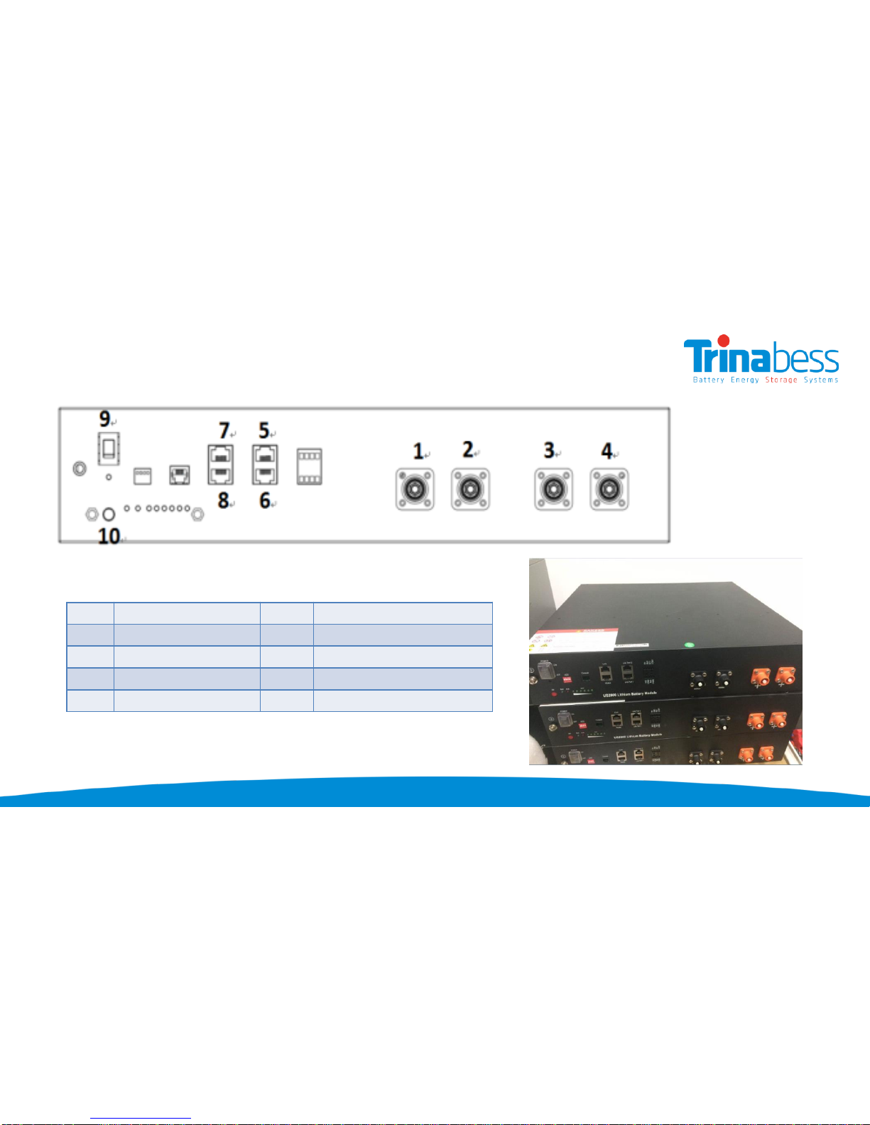
System connection –Powercube Battery pack overview
CP
1
Cathode
(-)
CP
6
Link
Port 1
CP
2
Cathode
(-)
CP
7
CAN
CP
3
Anode
(+)
CP
8
RS
485
CP
4
Anode
(+)
CP
9
POWER
(ON/OFF)
CP
5
Link
Port 0
CP
10
Soft
Starter
Connection Points (CP)
20
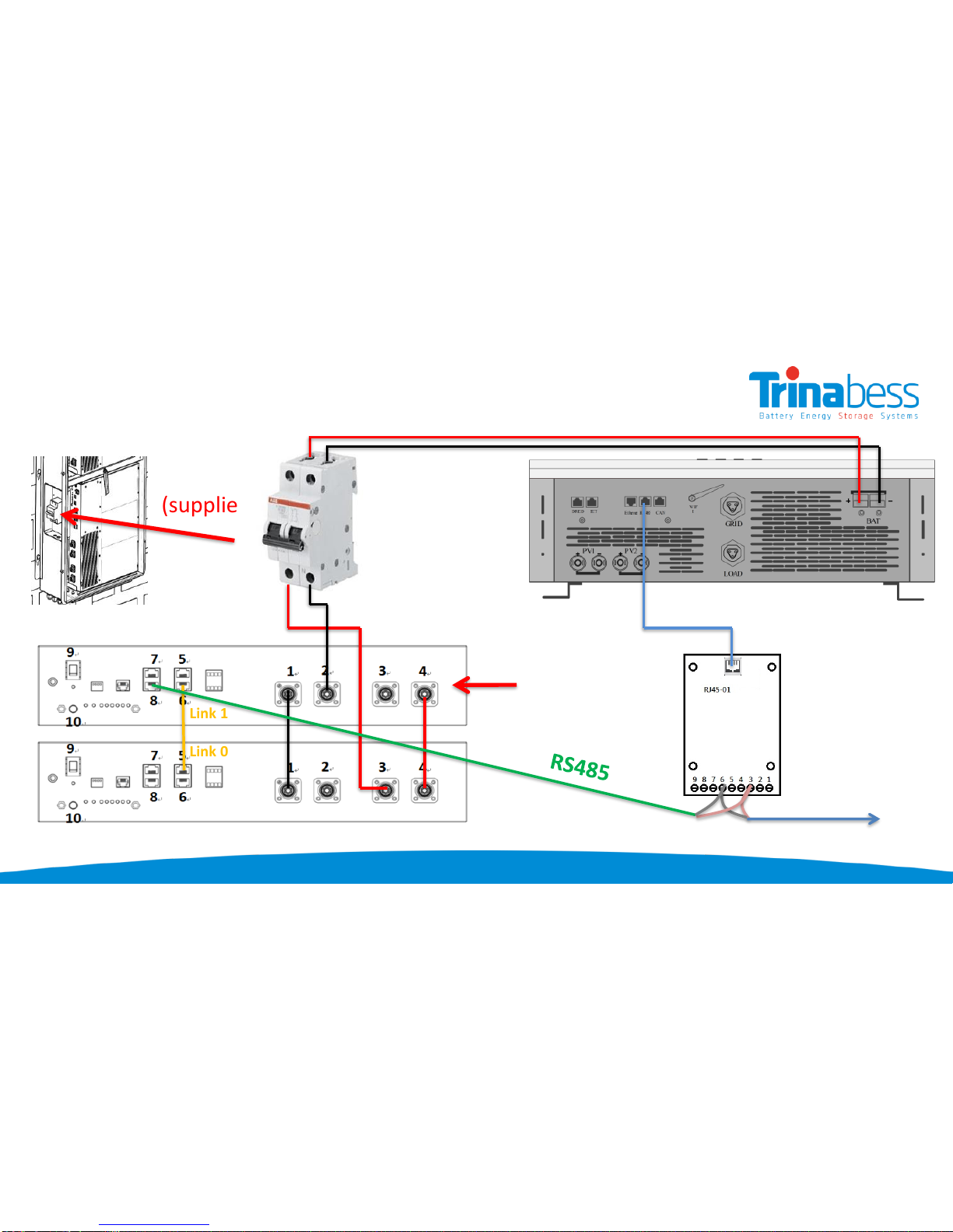
System connection - Battery Modules (2 Packs)
Connection - Wire
Powerbox (DC)
DC isolator
(supplied)
Powercube battery packs
Master
Link 1
Link 0
Comms Relay
Plate (supplied)
DC Positive cable
Energy Meter
DC Negative cable
Popular Camera Accessories manuals by other brands


ORION TELESCOPES & BINOCULARS
ORION TELESCOPES & BINOCULARS Solar StarSeeker 10382 instruction manual
 Setup guide")
Convergent Design
Convergent Design Odyssey7Q ProRes 422 (HQ) Setup guide

Aquatica Digital
Aquatica Digital Pro Digital 20062 operating manual

Califone
Califone TP285 Specifications

isvi
isvi IC-M29S-CL Operation manual

Dynex
Dynex DX-TRPFLX Guide d'installation rapide