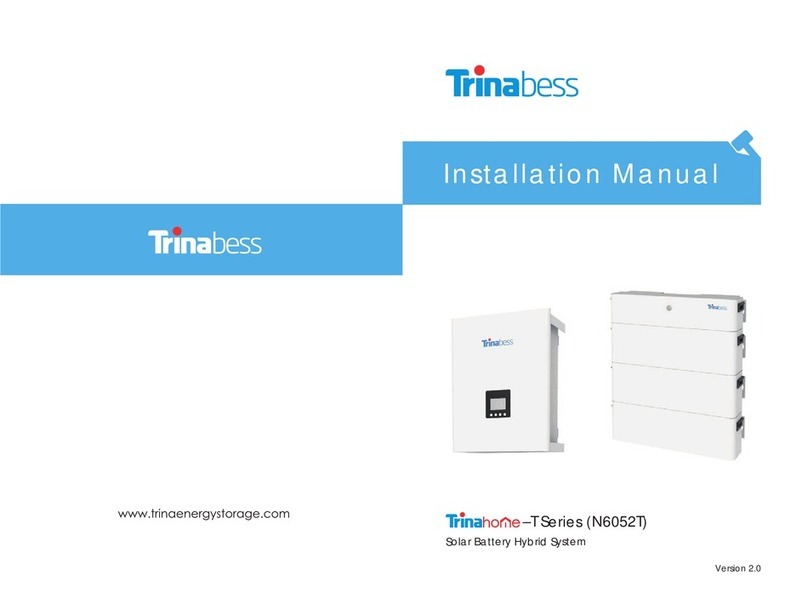
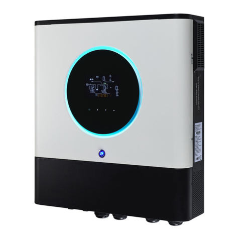
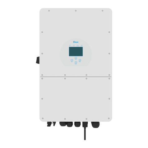
Trinabess Trinahome T Series User manual

User Manual
Solar Battery Hybrid System
T series
Trina Energy Storage Solutions (Jiangsu) Co., Ltd.
Tel: +86 519 8517 6686
Add: No. 2 Tianhe Road, Trina PV Park, New District,
Changzhou, Jiangsu, 213031
E-Mail: [email protected]
China
〒105-6133東京都港区浜松町二丁目4番1号
Tel: +81 (0) 3 6432 0581
トリナ·エナジー·ストレジー·ジャパン株式会社
世界貿易センタービル21階
E-Mail: [email protected]
Japan
Trina Energie Storage Vertrieb und Service GmbH
Add: Otto-Schott-Str.4, 60438, Frankfurt am Main, Germany
E-Mail: [email protected]
Europe
Tel: +49 (0) 69 75844 361
Tel: +61 2 8034 6313
E-Mail: [email protected]
Oceania
Add: Unit 60, 20 - 28 Maddox Street, Alexandria,
NSW 2015, Australia
Trina Energy Storage Solutions (Australia) Pty. Ltd.
Tel: +86 519 8517 6686
E-Mail: [email protected]
Singapore
Add: 600 North Bridge Road, #12-01 Parkview Square,
Singapore 188778
Trina Energy Storage Solutions (Singapore) PTE. Ltd.
www.trinaenergystorage.com
Technical Service Provided by
WI - UM - T Series - 0002 2018 V3.0_EN

Trina Energy Storage Solutions (Jiangsu) Co., Ltd. (Trinabess)
NO. 2 Tianhe Road, Trina PV Park, New District, Changzhou,
Jiangsu, P.R.China.
Tel: +86 519 8517 6686
The details of this documentation are the property of
Trinabess.
Using and publicizing this documentation, even if only in
parts require the written consent of Trinabess.
All information in this documentation has been compiled
and checked with most care. Despite of this, errors or
deviations cannot be completely excluded. We assume
no liability therefore.
User is encouraged to check updated version at
http://www.trinaenergystorage.com/
Published by
Legal Disclaimer
Copyright
Preface

Content
1. Safety
2. System Description
3. LCD Description
4. Cloud Platform
5. Troubleshooting
4.1.1 Create New User
4.1.2 Recovery of Password
4.1.3 Logout
4.1.4 Modify Personal Password
4.2.1 Menu Bar
4.2.2 Basic Information of Device
4.2.3 Basic Energy Statistics
4.2.4 System Diagram
4.2.5 Language
4.3.1 Power Diagram
4.3.2 History Data
4.4.1 IOS
4.4.2 Android
1.1 Important Safety Information
1.2 Safety Rules
1.3 Exclusion of Liability
3.1 LCD Interface and Indication Lights
3.2 LCD Display Definition
3.3 LCD Display Menu Definition
4.1 User Account Registration
4.2 Online Overview
4.3 Online Monitoring
4.4 Download and Use APP
5.1 Safety During Troubleshooting
5.2 Fault Messages and Actions List
5.3 Fault Acknowledgement
01
01
02
03
04
05
05
06
07
08
08
08
09
09
10
11
12
12
12
13
16
16
16
17
19
19
20
21
21
21
26

01
The following operating and maintenance instructions must be read before performing
system installation, operation and maintenance acitivities.
Check for damage on the device and package. If you are in doubt, please contact us
or the distributor before installing the device. Do not install damaged batteries!
Before connecting the solar modules or battery packs with the product, please check
the voltages and make sure they are within the limits of the Trina inverter
specifications. Failure to observe these specifications could void your warranty.
Only personnel trained and qualified with local electrical codes may work with the
electrical installations. For safety, please follow the steps described in this manual.
Please refer to “Disconnecting for maintenance”. Note that, after disconnecting the
hybrid inverter from power grid, PV panels and battery packs, wait at least 15 minutes
before the next proceeding.
Do not commission the device until the whole system complies with the
application-specific national rules and safety regulations.
The ambient conditions given in the product documentation (data sheet) must be
observed.
The device manufacturer or installer is responsible for compliance with the limit
values as prescribed in the national regulations.
Only persons who are trained and qualified for the use and operation of this device
are authorized to work on the device.
Only authorised personnel are allowed to repair or modify the inverter. To ensure
safety for user and environment, only the original spare parts available from your
supplier should be used.
Unauthorised changes of functional safety parameters may cause injury or accidents
to people or inverter. Additionally it will lead to the cancellation of all inverter operating
approval certificates.
1. Safety
1.1 Important Safety Information
1.1.1 Before Installation
1.1.2 Installation
1.1.3 Disconnecting the Product
1.1.4 Operating the Product
1.1.5 Maintenance and Modification
1.1.6 Functional Safety Parameters
Installation Manual
Solar Battery Hybrid System (T Series)

02
The following warning notices are adopted in safety related guidelines to describe the
various risk grade:
Death or severe personal injury will occur.
Death or severe personal injury may occur.
Personal injury or material damage may occur.
Do not open the device! Dangerous voltage may still be applied
inside the device even after it has been switched off.
Make absolutely sure you have established earthing system before
connecting the device to the supply circuit!
Health risk for persons with cardiac pacemakers, metallic implants
and hearing aids in the immediate vicinity of electrical equipment!
Personal injury mechanically by crushing, shearing, cutting or
striking.
If the inverter is operated with the wrong country code, the power
supply company may cancel the operating license.
Surfaces of the housing can be hot! Risk of injury! Risk of burns.
The housing top and the heat sinks may have a surface temperature
up to 70°C.
Do not place nor install near flammable or explosive materials.
Install the product out of reach of children.
Read the instruction manual before starting installation and
operation.
1.2 Safety Rules
DANGER
WARNING
CAUTION
HOT SURFACE
Electric shock!
High leakeage current!
Health risk!
Risk of improper handling!
Cancellation of the operating license!
Installation Manual
Solar Battery Hybrid System (T Series)

03
Heavy weight may cause serious injury to the back.
Observe a waiting time of 15 minutes.
Do not dispose of the product with household wastes.
Recyclable.
Disconnect the equipment before carrying out maintenance or repair.
Observe precautions for handling electrostatic discharge sensitive
devices.
15min
1.3 Exclusion of Liability
Trinabess will not be liable for any direct, indirect or consequential damages, losses or
costs including without restriction any economic losses of any kind, any loss or damage to
property, any personal injury, any damage or injury arising from or as a result of misuse or
abuse, or the incorrect installation, integration or operation of the product. We disclaim
any liability for direct or indirect damages due to:
1. Improper installation or commissioning,
2. Unauthorized modifications, alterations or repair attempts,
3. Inappropriate use or operation,
4. Insufficient ventilation of the device,
5. Non-compliance with relevant safety standards or regulations,
6. Flood, lightning, overvoltage, storm and fire (acts of nature).
We do not assume any liability for an incorrect country code setting.
We reserve the right to make alterations that will improve device function.
Installation Manual
Solar Battery Hybrid System (T Series)

Figure 2.1 System main parts
The system includes three main parts: hybrid inverter (with integrated EMS), battery
packs and energy meter.
A B C
A) Hybrid inverter
The hybrid inverter converts the DC power generated by PV modules to AC power. During
the daytime, the PV power will be first used by the household load, then the surplus be
charged into battery packs for later use. Any further surplus PV power will be fed into
public grid.
During the nighttime, the hybrid inverter will discharge the battery to supply the load.
B) Battery packs
Battery packs store the energy generated from the hybrid inverter. Each battery module
capacity is 3 kWh, the system capacity is extendable by adding more battery modules.
The capacity can be expanded to 18kWh.
C) Trina energy meter
The bi-directional energy meter is used for data collection and communication. With the
meter data, the hybrid inverter decides when to charge/discharge the battery packs.
2. System Description
04 User Manual
Solar Battery Hybrid System (T Series)

3. LCD Description
3.1 LCD Interface and Indication Lights
All information related to the inverter can be obtained from the LCD display. There are 4
navigation keys on the LCD display panel. The functions of these navigation keys and
indication lights on the LCD screen are illustrated below:
ESC OK
~
Symbol Definition Description
Cancel
Up
Down
Enter/Escape
System operation light
Battery operation light
Wi-Fi operation light
Warning light
Move back to the previous item or close
Move forward to next item or next page
Enter into or exit from the current page
Light on when the WiFi is running
Light on when system warning occurs
Move back to the upper item or previous
page
Light on when hybrid inverter system is
running smoothly
Light on if the communication between
PV inverter and BMS is fine
05
Figure 3.1 LCD screen
Table 3.1 LCD function & status light definition
User Manual
Solar Battery Hybrid System (T Series)

3.2 LCD Display Definition
06
Table 3.2 LCD display definition
Figure 3.2 LCD display
User Manual
Solar Battery Hybrid System (T Series)
Time
PV1 power
PV2 power
Grid power
Load power
Battery power
Menu
System status
Energy
Current date and time
Power of PV1
Power of PV2
Power import from/export to grid
The current load power
Battery charging/discharging power
Menu and data display
Operating status of the inverter (Wait/Start/Normal
/Warning/Fault/Off-grid)
EIN/EOUT/EPV/ELD
EIN: battery charging energy
EOUT: battery discharging energy
EPV: PV generated energy
ELD: load energy
1
4
5
6
7
8
9
2
3
ItemNo. Definition

3.3 LCD Display Menu Definition
The LCD menu includes display and setting menus. The display menu shows system
parameters and their values.
Users can change menu by pressing buttons to check information on the display
menu.
Parameter list as definition on display menu:
07
Figure 3.3 LCD display of menu data
Table 3.3 LCD display menu content
User Manual
Solar Battery Hybrid System (T Series)
The display and setting menu parameter may have minor differences beacause of
different product version.
*
PV1
PV2
BAT
L1
L2
L3
TEM
FRE
ET
SOC
SWC
SWM
NUM
Voltage Current
Voltage Current
Voltage Current
Voltage Current
Voltage Current
Voltage Current
Temperature
Grid frequency
Daily PV production
Battery capacity
Software version no. of inverter communication conversion board
CPU software version no.
Communication with BMS, 01 is ok
Item Definition

4.1 User Account Registration
4.1.1 Create New User
Username: free to create (with 5-15
letters/figures) .
Email Address: fill in a frequently-used
email address. ( in case of forgetting
the actual password ) .
Hybrid: the type of your device, it can
be selected Hybrid only.
Device Serial Number: EMS serial
number (on the right side of your
inverter) .
Location: choose the address of your
device on the google map.
Password: 5-15 letters/figures, etc.
Confirm Password.
*
*
*
*
*
*
*
when username is created,
it cannot be changed.
Visit the website portal http://cloud.trinabess.com and click “register”, then the user
register interface will be displayed.
You can set the place where your device is installed. Users should choose the country
and state in the pull-down list and input the definite address information. Address,
longitude and latitude can input information automatically by system.
Click “Register” to finish.
User account registration should be done on the computer. The browser
must be one of the following: IE/EDGE/Firefox/Chrome
NOTE:
NOTE:
08
Figure 4.1 User register
User Manual
Solar Battery Hybrid System (T Series)
4. Cloud Platform

4.1.2 Recovery of Password
4.1.3 Logout
If you forgot your password, please click “Forgot password” on the login page, following
windows will pop up to reset your password;
Fill out your “Username” and “Email Address” and send it by clicking the button “OK”, you
will now receive an email in your mailbox with your “Username”.
Please always logout after finishing your monitoring to ensure that nobody uses your
account without permission.
Click this button to log out from the web server.
09
Figure 4.2 Recoery of password
Figure 4.3 User logout
User Manual
Solar Battery Hybrid System (T Series)

4.1.4 Modify Personal Password
Click the link , you can change your password by inputting your
email.
Figure 4.4 User logout
10 User Manual
Solar Battery Hybrid System (T Series)

Please read for detailed information the following Chapter 4.2.1 to 4.2.5.
4.2 Online Overview
1
2
3
4
4.1
4.2
4.3
4.4
4.5
5
6
Menu Bar
Basic Information of Device
Basic Energy Statistics
Real-time System Diagram
PV Power
Battery Data
Grid Power
Load Power
Inverter Data
Location
Language
Item
Definition
11
1
5
6
24
3
4.1
4.5
4.3
4.2 4.4
Figure 4.5 Online overview
User Manual
Solar Battery Hybrid System (T Series)

4.2.1 Menu Bar
If you click these links, you can enter “System Overview”,
“System Monitor” and “History” pages.
Figure 4.6 Menu bar
4.2.2 Basic Information of Device
4.2.3 Basic Energy Statistics
Device Serial Number: serial number of
the device;
Capacity: maximal power of the device;
Network: the connecting status of the
device (Offline/Online);
Status: the status of the device
(Normal/Unknown/Warning);
Battery Capacity: the capacity of
battery packs;
PV Install Power: the total PV power
System Type: AC/DC/Hybrid
HEMS/PCS Version
*
*
*
*
*
*
*
*
*
*
*
*
*
*
Today's generation: today’s energy
generated by PV system;
Today's feed-in: today’s feed-in energy
to the grid;
Today's consumption: today’s energy
consumption from grid;
Total generation: total energy
generated by PV system;
Total feed-in: total feed-in energy to
the grid
Total consumption: total energy
consumption from grid;
12
Figure 4.7 Basic information of device
Figure 4.8 Basic energy statistics
User Manual
Solar Battery Hybrid System (T Series)

4.2.4 System Diagram
4.2.4.1 PV Power
It shows the current power consumption
value of PV, load, battery, feed-in and grid.
In addition, the detailed data of the battery
and inverter is showed.
It shows the current power of the PV system.
Click the picture you will see the detail information of the
battery as follow.
13
Figure 4.9 Real-time system diagram
Figure 4.10 PV power
Figure 4.11 Battery data
4.2.4.2 Battery Data
User Manual
Solar Battery Hybrid System (T Series)

SOC: State of Charge;
Status: Charge, Discharge, Standby;
Bat Voltage: total voltage of the battery
packs;
Bat Current: current of the battery packs;
Bat Power: total power of the battery
packs;
Max Cell Voltage: maximal voltage in all
cells;
Min Cell Voltage: minimal voltage in all
cells;
Max Cell Temperature: maximal
temperature in all cells;
Min Cell Temperature: minimal
temperature in all cells;
Max Voltage Module ID: ID of battery
module that has maximal voltage;
Min Voltage Module ID: ID of battery
module that has minimal voltage;
Max Temperature Module ID: ID of battery
module that has maximal temperature;
Min Temperature Module ID: ID of battery
module which has minimal temperature.
*
*
*
*
*
*
*
*
*
*
*
*
*
14
Figure 4.12 Battery detailed data
4.2.4.3 Grid Power
Display the power of grid, including consumption and feed-in.
Figure 4.13 Power of grid
User Manual
Solar Battery Hybrid System (T Series)

4.2.4.4 Load Power
4.2.4.5 Inverter Data
*
*
*
*
*
*
*
*
*
*
*
*
*
PV1 Current: current of No.1 PV system;
PV1 Voltage: voltage of No.1 PV system;
PV2 Current: current of No.2 PV system;
PV2 Voltage: voltage of No.2 PV system;
R/S/T Phase Current: current of R/S/T
phase;
R/S/T Phase Voltage: voltage of R/S/T
phase;
R/S/T Phase Frequency: frequency of
R/S/T phase;
PV Power Now: current power of PV
system;
Temperature: temperature of the inverter;
PV Today’s Energy: today’s energy
generated by PV;
PV Total Energy: total energy generated
by PV;
Today’s Running: today’s running of the
inverter (minute);
Total Running: total running duration of
the inverter (hour).
Display the power of all loads, including the system loss.
Click the picture you will see the detailed information of the
inverter.
15
Figure 4.16 Inverter detailed data
User Manual
Solar Battery Hybrid System (T Series)
Figure 4.14 Power of load
Figure 4.15 Inverter data

It shows the power value of PV, load, battery, feed-in and grid consumption. When the
battery power is positive number, the battery is in the state of charging, otherwise,
discharging.
4.2.5 Language
4.3.1 Power Diagram
Click the link “Language”, you can switch among 4
languages including Chinese, English, Japanese and
German.
16
Figure 4.17 Language
Figure 4.18 Power diagram
4.3 Online Monitoring
User Manual
Solar Battery Hybrid System (T Series)

4.3.2.1 Statistical Diagram
It shows the total energy of PV, Load, Battery, Feed-in and Grid consumption;
Click the icon “Statistical Diagram”, to display the energy of total battery charging and
discharging;
In addition, when you click the button of “Export CSV” or “Export PDF” you can export
data in the format of CSV or PDF;
Buttons “Month”, “Year”, “Over Years” are used to click for changing the date range of
statistics.
4.3.2 History Data
17
Figure 4.19 Statistical diagram
User Manual
Solar Battery Hybrid System (T Series)
Other manuals for Trinahome T Series
1
Table of contents
Other Trinabess Inverter manuals
