PSC Solar 10KW User manual

USER MANUAL
Sate
Copyright, copying and plagiarism without any authorization is prohibited
The company is committed to the continuous improvement of the inverter. This information is subject to change without notice. please refer to the
actual product.
3PHASE HYBRID
INVERTER
10-200KW

Contents
I.Brief Introduction............................................................................................................................. ...................3
A. General Instructions..................................................................................................................................... ..3
B. Cautions............................................................................................................................................................3
II.Installation and Wiring of the Inverter...............................................................................................................3
A.Environment for Installation.............................................................................................................................3
B.Inspection before Installation...........................................................................................................................4
C.Installation Position...........................................................................................................................................4
D.Wiring..................................................................................................................................................................4
1.Output System for 10-200KW inverter 3 phases type.....................................................................................4
2.Wiring Inspection................................................................................................................................................5
III.Operation of the Inverter -1............................................................................................................................5
A.Procedures of Switching on Single Machine...................................................................................................5
B.Procedures of Regular Switching Off ..............................................................................................................6
IV.Operation of the Inverter -2............................................................................................................................6
A.Mains priority.......................................................................................................................................................6
B.Battery Mode.......................................................................................................................................................6
C.Static Bypass Mode...........................................................................................................................................7
D.Reparing Mode...................................................................................................................................................8
E.SLU......................................................................................................................................................................8
F.Battery..................................................................................................................................................................8
G.Turn to Bypass with Inverter's Off....................................................................................................................8
V.Maintenance........................................................................................................................................................8
A.Periodically Maintenance..................................................................................................................................8
B.Battery Maintenance..........................................................................................................................................9
C.Adjusting a Suitable Working Environment.....................................................................................................9
VI.Parameters For..................................................................................................................................................9
A.Inverter System..................................................................................................................................................9
1.Input Rectifier ....................................................................................................................................................9
2.Output Rectifier..................................................................................................................................................9
B.Battery...............................................................................................................................................................10
C.Inverter..............................................................................................................................................................10
D.Bypass...............................................................................................................................................................11
E.System...............................................................................................................................................................11
VII.Alarms.............................................................................................................................................................12
A.Alarm1:Fault of Bypass Voltage or Bypass Fuse, SCR................................................................................12
B.Alarm2:Fault of Mains Power or Input Rectifier Switch Disconnects ........................................................12
C.Alarm3:Under-Voltage of the Battery..............................................................................................................12

D.Alarm4:Battery Discharging...........................................................................................................................12
E.Alarm5:Over-loaded........................................................................................................................................13
F.Alarm6:Temporary Bypass..............................................................................................................................13
G.Alarm7:Turn to Bypass due to Over-loaded..................................................................................................13
H.Alarm8:Order to Bypass .................................................................................................................................13
I.Alarm9:Over-heat or Fault of Cooling Fans.....................................................................................................13
VIII.Display Function............................................................................................................................................13
A. General Introduction......................................................................................................................................13
1.Instruction on LCD Indicators..........................................................................................................................13
2.Instruction on Main Screen..............................................................................................................................14
3.Introduction on Display Content................................................................................................................15-17
IX.Connection with Computer.............................................................................................................................18

3rd
A. General Instructions for inverter
The product is the DC power (battery, storage battery) into alternating current (380V, 50Hz sine wave).It consists
of an inverter bridge, control logic, and filter circuit.Widely used in air conditioners, home theater, electric grinders,
power tools, sewing machines, computers, televisions, washing machines, range hoods, refrigerators, VCRs,
massage, fans, lighting, etc.By connecting the cable to the battery, the appliances connected to the output of the
machine will be able to use a variety of electrical appliances. Appliances can be used are: mobile phones, laptop
computers, digital cameras, cameras, lighting, electric shavers, game consoles, handheld computers, power tools,
car refrigerator and all kinds of travel, camping, medical and first aid appliances.This is an all-digital controldesign,
the application of intelligent DSP digital intelligent engine control, take-frequency architecture, the new inverter
products.Particularly suitable for harsh environment area of power and the use of photovoltaic power generation,
pure sine wave output, you can drive all types of loads.
B.CAUTIONS
1.Ground Protection. The ground wire of the input power must be connected to the ground terminal
(with sign "G") of the inverter.
2. It's not allowed to dismantle any wire without permission.
3.Risk of electric shock, do not remove cover. No user serviceable parts inside. Refer servicing to qualified
service personnel. And please read the used manual carefully when service required.
4.Always keep the top metal cover and rear panel fixed. The location should provide adequate air flow around the
nit, in an atmosphere free of excessive dust or corrosive fumes.
5. It's prohibited to remove dirt under power connection. Wet or soaked material is not allowed to use for
cleaning.
6.Risk of electric shock hazardous live parts inside this unit are energized from the battery supply even when the
input AC power is disconnected.
7.To reduce the risk of fire, replace only with same type and rating of fuse.
8.The replacement of the batteries should be conducted by qualified personnel. As the used battery is deemed to
be poisonous material, it should be delivered to recollection agency
9.This unit requires operation environment of around 25℃. When the inverter is not in use for long term, battery
should be charged every 3 months. If the temperature is above 30℃, battery should be charged every 2 months.
10.Install this inverter strictly according to this manual.
A.Environment for Installation
Make sure the indoor envrionment for installation to be:
1.without dust;
2.at appropriate temperature:
Working temperature: 0~40 ℃
Starting temperature: above 0℃
Optimum working temperature: 25℃
Good ventilation is required:
(1)Natural ventilation; applicable in special room without heat.
(2) Manual ventilation:
When the outer case temperature (TA) is higher than the surrounding temperature (TE), air
I.INTRODUCTION
II.INSTALLATION AND WIRING
4th
conditioner is needed.
The closer are these two temperatures, the larger capacity of the ventilation system would be,
based on the following equation:
Q(m³/h)=3. 1+Pdiss(kcal)/(ta-te)(c)
kcal is the unit of Pdiss , adjust Pdiss 10% for allowing the loss of energy.
B.Inspection before Installation
After putting out the Inverter from the packing box, please check :
whether there's any damage on it;
whether the switches are OFF;
any of the mentioned accessories missing;
C.Installation Position
Please make Sure:
1. Nothing is within 40cm to the back of the Inverter;
2. Nothing shall be put on the top of the Inverter;
3. There should be enough space to the front and top of the Inverter for inspection and reparing;
4. Battery cabinet should be placed on the right side of the machine and keep enough space in
between for installing and reparing;
5. Power cable should be installed from the bottom or back of the Inverter.
D.Wiring
Remember to turn off all the switches before connecting Inverter to the main power cable or any
loads.
when wiring the main power cable, please first connect the ground line to the "G" port on
the terminal board. Without ground connection, the machine can't be operated.
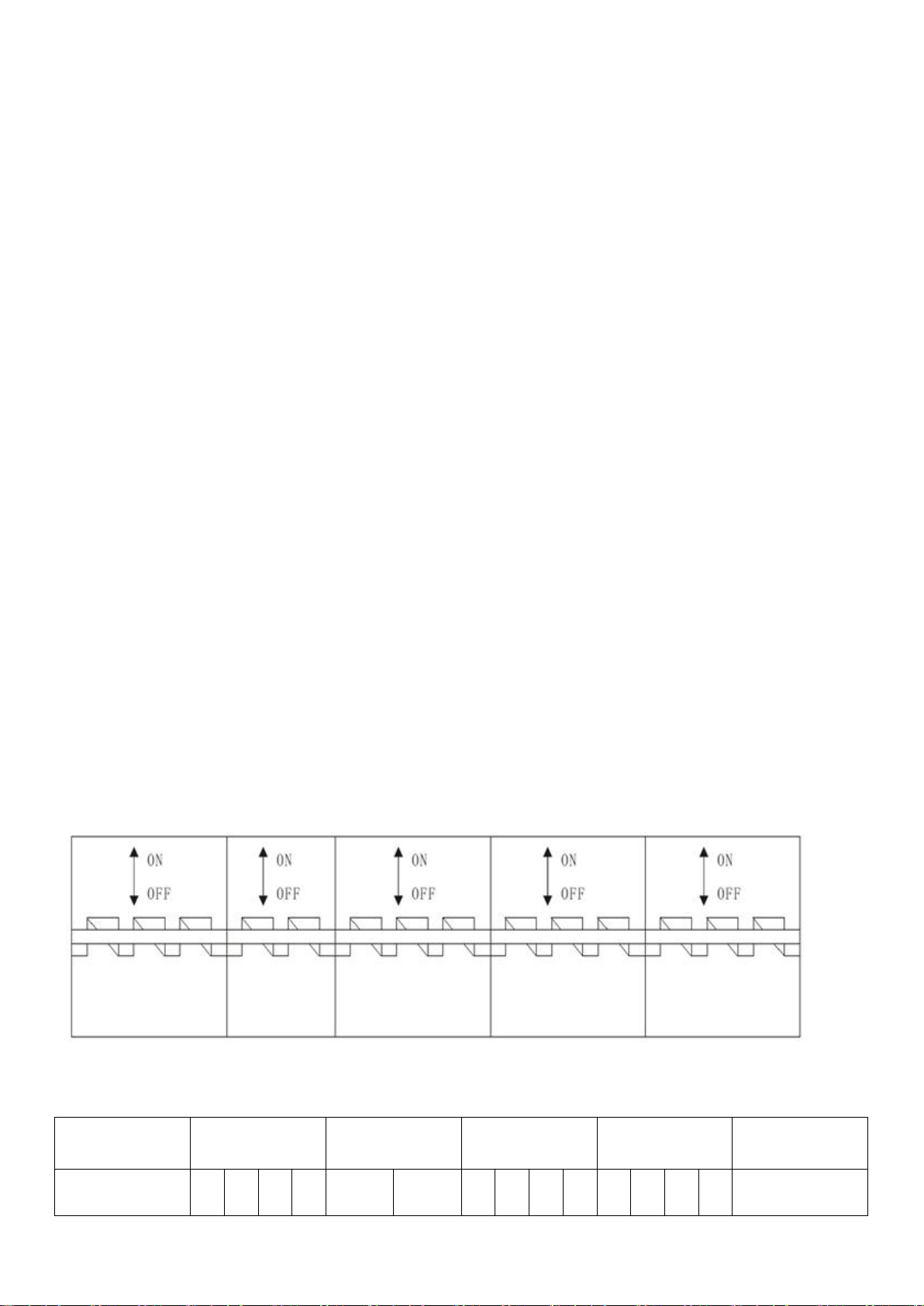
1.Output System for 10-200KW inverter 3 phases type
(1) 3 Phases Input and one neutral line (3ϕ4W 380V)
(2) The positions of Input/Output in the distributor are as below:
(3) The Graph 2 shows all of the terminal boards:
Graph 2
Ground
Rectifier Input
Battery
Bypass Input
Output
Ground
G
N
R
S
T
+
-
R
S
T
N
R
S
T
N
G
Graph 1

5th
(4) Cable size for Input / Output , shown as the below table: (mm²)
Model
Input (including Bypass)
Output
Battery
R
S
T
N
G
R
S
T
N
Positive
Negative
10KW
6
6
6
6
6
6
6
6
6
10
10
15KW
6
6
6
6
6
6
6
6
6
10
10
20KW
16
16
16
16
6
16
16
16
16
20
20
30KW
16
16
16
16
10
16
16
16
16
20
20
40KW
25
25
25
25
10
25
25
25
25
30
30
50KW
25
25
25
25
25
25
25
25
25
35
35
60KW
35
35
35
35
25
35
35
35
35
50
50
80KW
35
35
35
35
30
35
35
35
35
50
50
100KW
50
50
50
50
30
50
50
50
50
80
80
120KW
50
50
50
50
35
50
50
50
50
80
80
140KW
80
80
80
80
35
80
80
80
80
100
100
160KW
80
80
80
80
50
80
80
80
80
100
100
200KW
100
100
100
100
50
100
100
100
100
120
120
2.Wiring Inspection
After finishing wiring all of the input/output cables, the following should be inspected:
(1) whether the order of the phases is correct;
(2) whether battery input cable is connected with the correct polarity;
(3) whether the ground connection cables of the Input and Output have been connected to the terminal board
firmly.
Notice: The Bypass input cables (R,S,T) and the Rectifier input cables (R,S,T) are paralleled connected.
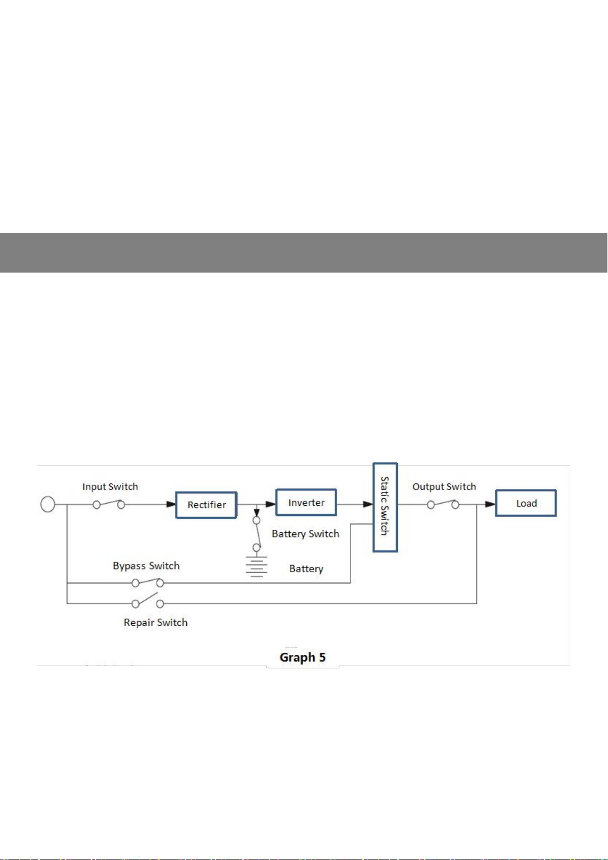
A.Procedures of Switching on Single Machine
Please switch on the inverter according to the following procedures after wiring all of the necessary cables
properly
1. Close up the input switch of rectifier to start the rectifier of the inverter after confirming that all the phases
have voltage;
If no display on the LCD screen, and there's long buzzes, it indicates that the input phases are not in correct order;
then rectifier switch should be turned off and input power bus should be disconnected until the input phases
(R,S,T) are wired in correct order;
Close up the rectifier switch again and LCD screen shall have display. Then it takes around 30s for
self-inspection before starting the inverter;
The spinning fans indicate that the inverter has started up .
2. The Battery Switch can not be closed up until the inverter has started;
3. Close up the Bypass Switch;
4. Close up the Output Switch.
Note: When the inverter is working normally, the Repair Switch should be disconnected, otherwise the
mains power would go through repair switch directly to the loads.
III.Operation of the Inverter -1
6th
B.Procedures of Regular Switching Off
1. Disconnect the output switch;
2. Disconnect the Bypass Switch;
3. Disconnect the Battery Switch;
4. Disconnect the Rectifier Input Switch;
5. Disconnect the main power switch.
Warning:
1. Please strictly follow the above procedures to turn off the inverter;
2. The above actions should be done continuously until all of the switches are disconnected.
B.Mains priority
AC first , DC standby INVERTER mode
When both utility and battery are connected to the machine, utility will supply power to the loads prior to the battery. When
utility is cut off, the battery will automatically continue to supply power.
Step 1: When utility power is available, it will output directly after voltage being stabilized and charge batteries at the same
time.
Step 2: When utility power is cut off suddenly, the inverter will convert
DC power to AC power automatically to ensure uninterrupted power supply within 5ms.
Step 3: When utility power becomes available again, it will automatically transfer to utility supplying power to loads and
charge batteries at the same time.
See Workflow as below:
B.Battery priority
DC first, AC standby:
When both utility and battery are connected to the inverter, battery will supply power to the loads prior to utility.
When battery capacity is not enough, utility will continue to supply power automatically.
Steps are as follows:
Step 1: When battery has enough power, it will supply power to the loads directly
Step 2: When battery does not have enough power, it will automatically transfer to utility supplying power to the
loads
IV.Operation of the Inverter -2

7th
Step 3: After the battery is fully charged (e.g. by solar or wind charge controller), it will then automatically transfer
to battery supplying power to the loads.
See Workflow as below:
Note: Battery supporting time would be affected by the power consumption of the loads and
temperature. Removing some of the loads can extend battery time.
Under the battery mode, the alarm would buzz interruptedly, and the indicators of Output and Battery on
the control panel would show green light.
The closer to the exhaustion of the batteries, the more frequent would the buzzers go, with battery
indicator flashing at the same time. Inverter will stop working when the batteries exhaust until the
power come back for supplying and charging the batteries.
C.Static Bypass Mode
The inverter will turn to Static Bypass mode under any of the following situations:
1. order of transfer to Bypass (manually or automatically);
2. Output over-loaded;
3. Fault.
Under this mode, the bypass LED indicator on the control panel (Yellow light) will light on.
Note: The static bypass switch should be synchronized with AC power; It can be manually or
automatically set to 0 transfer time from protective load (inverting output) to non-protective load (Bypass
output)

8th
D.Reparing Mode
Used when the inverter needs repairing without cutting the power for the loads.
When Repair Switch is closed, the control panel stops displaying, and eletricity goes from bypass route to the
load and the load will be affected by any interference on the power grid.
Batteries cannot supply the power for loads; Shown as the Graph 8
Note: Before repairing the machine, manually close up the Repair Switch and disconnect all the other
switches (Input Switch, Output Switch , Battery Switch and Bypass Switch). Then apart from the voltage
on the switch part, there's no current going through the internal components of the inverter and the loads
are still having power supply.
But non-qualified personnel is not allowed to use the Repair Switch.
E.SLU
All of the operation action of this inverter is controlled by DSP chip.
F.Battery
It supplies the power for inverter. Choose battery quantity and capacity according to the type of the
inverter and the required back-up time.
G.Turn to Bypass with Inverter's Off
Under the normal situation, if the orders to turn off the inverter part, the loads will be supplied by power from
static bypass. If the mains power fails, the loads will not have power supply.
Under the emergency situation, if the inverter receives order of turning off the inverter part, the inverter will shut
down completely until the power getting back to normal, then it will start the normal working mode automatically.
Note: Since Input Switch and Battery Switch shall have voltage remains even they are disconnected, only
qualified personnel is permitted to repair the inverter. Otherwise the inverter may be damaged or worse,
accidents occurs to human being.
A.Periodically Maintenance
Batteries and cooling fans are the items that should be inspected periodically.
1. Inspect the cooling fans and clean its dust;
2. Replacing the batteries should be done by qualified personnel. All the disused batteries should be returned to
the related re-collection institute as the disused battery is deemed to be "Poisonous Waste".
V.Maintenance

9th
3. Battery life is related to the designed cycles of charging-discharging and the working temperature. Usually,
under 20 ℃, battery life can be 3~5 years. If the environmental temperature of the battery is above 30 ℃, battery
life would 1.5~2.5 years.
After a few times of charging-discharging cycles, the battery capacity would increase and be stable for the next
hundreds of cycles. Then it will shrink.
B.Battery Maintenance
Battery maintenance should be executed as follows:
1. Keep the environment temperature at around: 20~25 ℃;
2. In the first month, 2~3 times of charging and discharging the batteris is advised;
3. After the first month, batteries should be charged and discharged once every 3 months.
C.Adjusting a Suitable Working Environment
Adjustable items: Battery alarm setting; Automatic Switch-off; Bypass Voltage Range; Bypass Frequency
A.Inverter System
1.Input Rectifier shown as table 1
Model
10KW
15KW
20KW
30KW
40KW
50KW
60KW
80KW
100KW
120KW
140KW
160KW
200KW
Max.
Input
Current
25A
38A
51A
75A
101A
125A
150A
199A
240A
300A
340A
388A
480A
Working
Principle
Online Power supply, with static bypass switch (uninterruptible transfer), output power isolated
Phase
3 phases, R S T +N+G
Nominal
Voltage
380vac ±25%
Nominal
Frequenc
y
50Hz / 60Hz ±10%
Voltage
Harmonic
Distortion
<5%
Soft Start
Time
0~100% 5 seconds
Table 1
2.Output Rectifier shown as Table 2
Model
10KW
15KW
20KW
30KW
40KW
50KW
60KW
80KW
100KW
120KW
140KW
160KW
200KW
Max.
Output
Voltage
216VDC
408VDC
432VDC
Charging
Current
5A ~30A (adjustable)
Table 2
VI.Parameters :

10th
B.Battery
Shown as Table 3
Model
10KW
15KW
20KW
30KW
40KW
50KW
60KW
80KW
100KW
120KW
140KW
160KW
200KW
Max.
Discharge
Current
52A
78A
104A
156A
125A
156A
187A
249A
311A
373A
435A
497A
559A
Battery
Voltage
192 VDC
360VDC
384VDC
Float
Charging
Voltage
216VDC
408VDC
432VDC
Charging
Current
5A ~30A (adjustable)
Table 3
C.Inverter
Shown as Table 4
Model
10KW
15KW
20KW
30KW
40KW
50KW
60KW
80KW
100KW
120KW
140KW
160KW
200KW
Power (KW)
10
15
20
30
40
50
60
80
100
120
140
160
200
Working
Method
SVPWM Full Bridge Inverting
Phase
3 phases, R S T +N+G
Nominal
Voltage
380vac ±1% (Stable Load)
Nominal
Frequency
50Hz / 60Hz ±0.5% (in Battery mode)
Frequency
Variation
<±0.05% (non-synchronized); <±2% (synchronized with Mains power);
Crest
Factory
3:1
Wave Form
Pure Sine Wave
THD
Linear loads: <3%; Non-linear loads: <5%
Fluctuation
of Voltage
for Unstable
Load
from 0~100% : <±5%
Transient
Recovery
Time
<10ms
On-Load
Voltage
Balance:<±1% Unbalance:<±5%
Overload
Capability
125% overload lasting 10Mins, 150% overload lasting 1min.
11th
Inverter
Efficiency
on 100%
load
90
92
92
92
93
93
93
93
95
95
95
95
95
Table 4
D.Bypass
Shown as Table 5
Model
10KW
15KW
20KW
30KW
40KW
50KW
60KW
80KW
100KW
120KW
140KW
160KW
200KW
Input
Current
25A
38A
50A
75A
105A
125A
150A
199A
240A
300A
340A
388A
480A
Phase
3 phases, R S T +N+G
Nominal
Voltage
380vac ±15% (Stable Load)
Nominal
Frequency
50Hz / 60Hz ±0.5% (in Battery mode)
Transfer
time to
bypass
10 ms
Table 5
D.MPPT
Shown as Table 6
Model
MPPT22050
MPPT36040
Input Max Current
45A
35A
PV Max Input Power
11KW
16KW
Nominal Voltage
330Vdc
480Vdc
PV Voltage Range
250~450Vdc
420~650Vdc
Output Max Power
10KW
14KW
Output Nominal Voltage
240Vdc
387Vdc
Output Voltage Range
192~264Vdc
310~425Vdc
Ourput Max Current
50A
40A
Table 6
F.System
Physical data shown as Table 7
Model
10KW
15KW
20KW
30KW
40KW
50KW
60KW
80KW
100KW
120KW
140KW
160KW
200KW
Output Bypass
Current
25A
38A
50A
75A
105A
125A
150A
199A
240A
300A
340A
388A
480A

12th
Efficiency
(100% load)
>85%
Communication
Port
RS232
Operating
Temperature
0~40℃;
Operating
Relative
Humidity
5%~95%
Operating
Altitude
>1000M(1% Power dcreased in every 100M increased. Maximum 4000M)
Cooling Method
Force Ventilation
Color
Black
Input Cable
From Bottom and Back
Maintenance
Side
Front / Top/ Flank side
Input Setup
Terminal Board
Output Setup
Terminal Board
Size (mm)
720*565*1140
790*660*1550
1100*900*1500
1380*950*1800
Weight(kg)
220
260
290
400
480
580
650
900
1100
1300
1350
1480
2000
Table 6
A.Alarm1:Fault of Bypass Voltage or Bypass Fuse, SCR
It alarms in the following situations:
1. Bypass input voltage fault;
2. Bypass Input Switch is disconnected;
3. Bypass SCR fuse disconnected or melt due to short circuit.
B.Alarm2:Fault of Main Input Power or Input Rectifier Switch Disconnects
It alarms in the following situations:
1. Input voltage is beyond 176~264 vac;
2. Input frequency is beyond 45~56 HZ;
3. Input Rectifier Switch is disconnected;
4. Rectifier fault.
C.Alarm3:Under-Voltage of the Battery
It alarms in the following situations:
1. Battery is under-voltage;
2. Battery running time is lower than the preset time;
VII..Alarms

13th
D.Alarm4:Battery Discharging
It alarms once the batteries start to discharge. In about 2 minutes, the alarm stops.
It alarms when the batteries capacity is close to exhausted voltage.
(The above happens without "Mute" being pressed)
E.Alarm5:Over-loaded
It alarms when load power exceeds 100% of the output power of the inverter;
Loads need to be reduced, otherwise the inverter will turn to bypass automatically.
F.Alarm6:Temporary Bypass
It alarms in the case of over-loaded, the inverter would turn to bypass mode temporarily , waiting for the inverter
to supply the inverting current.
G.Alarm7:Turn to Bypass due to Over-loaded
It alarms when over-loaded for long time. For example, the inverter can supply normal power for 10 minutes
when under 125% overloaded, then it will turn to bypass mode. If the load is reduced to <125%, the inverter
resume to the normal working mode.
H.Alarm8:Order to Bypass
By typing special order into the inverter , it can switch off the inverter and turn to Bypass without leaving record.
But the inverter will turn back to normal working mode after 1 minute unless a locked time has been set.
I.Alarm9:Over-heat or Fault of Cooling Fans
It alarms when the control system, inverter power module or rectifier power module gets over-heat or the cooling
fan is fault. Then the inverter turns to bypass mode.
A.General Introduction
1.Instruction on LCD Indicators
The operation control display panel is located on the front door.Through the operation control display panel,
operation control and query all parameters, battery status, and alarm information.As shown in figure 4-1, the
operation control display panel can be divided into three parts according to functions: analog current diagram,
LCD display and menu key, control operation key.The description of operation control display panel is shown in
table 4-1
4-1Operation control display panel part description
LED number
Function
LED number
Function
AC LINE
Ac input LED
BATLOW
Battery low voltage
BATTERY
Battery LED
BYPASS
Bypass LED
VIII.Display Function

14th
INVERTER
Inverter LED
OUTPUT
Load LED
ALARM
ALARM LED
1.2 LED
4-2 Description of led status
Sound warning (buzzer)
The alarm sound
Description
Half a second in singing
Battery low pressure alarm
Continue to sing
Battery high voltage, overload warning
LED
STATUS
MEANS
Ac Input LED
Green normally on
AC input works properly
Green flashing
Ac input anomaly
does not light
There is no AC input
Battery LED
Green normally on
Battery discharge inverter
Green flashing
Battery low pressure alarm
does not light
Battery does not work
Bypass LED
Yellow normally on
Load power is supplied by AC power
does not light
Bypass not working
Inverter LED
Green normally on
The load power supply is provided by the inverter
Green flashing
Inverter fault
does not light
The inverter is not working
Load LED
Green normally on
Output, and normal
does not light
There is no output
ALARM LED
Red normally on
There are warning signs
does not light
No alarm fault
BATLOW
Green normally on
Battery low voltage
15th
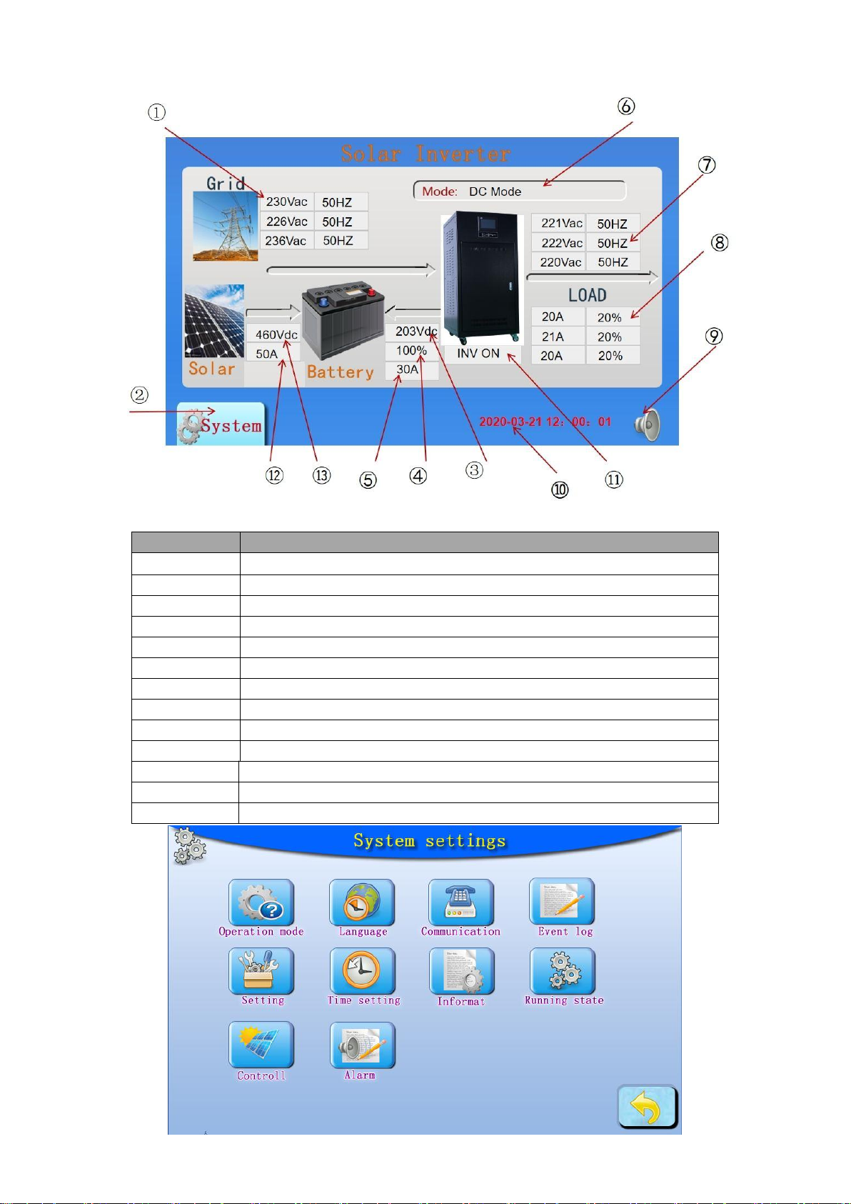
2. LCD display
graphics
instructions
1
Power input parameters
2
Entry operation
3
Battery voltage
4
Battery capacity % value
5
AC charging current
6
Current running mode
7
Output voltage parameter
8
Output load parameters
9
Mute and cancel the mute button
10
Current time date
11
Inverter on or off
12
Solar Voltage
13
Solar Current

16th
3. Operation Mode Setting:
3C.1 modification parameters:
Enter the password to modify and set parameters.
The factory password is: 123456
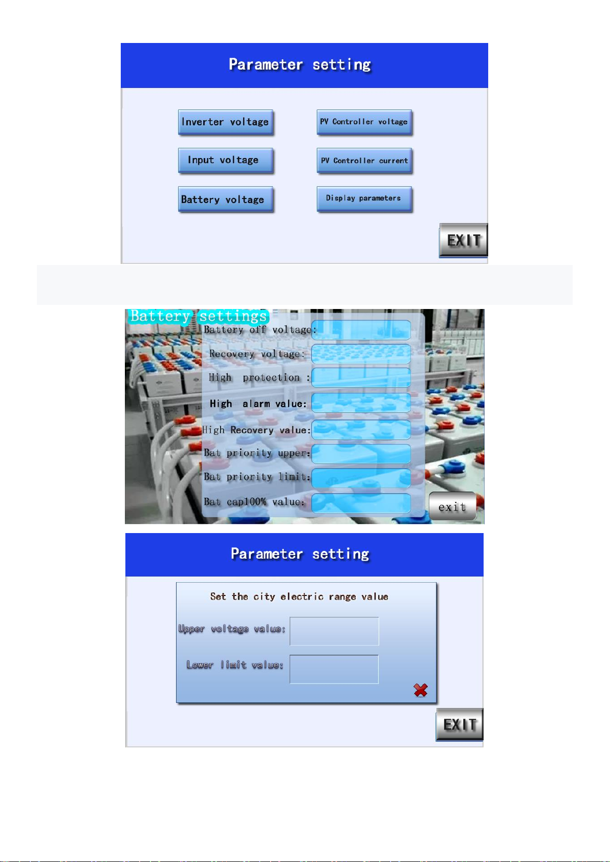
17th
3C.2 modify battery parameters:
Click directly in the blank of the battery and input the voltage value the user wants

18th
Packing List
Inverter
1 piece
User Manual
1 piece
Optional Accessories (Extra Charge)
1. N+1 Parallel Redundancy
2. SNMP Network card (Non inbuilt)
3. RS 422/RS 232 transferable port
4. Signal board for dry contact alarm
5. 12-pulse rectifying
6. All kinds of non-regular machine
PSC Solar UK
Physical Office/Warehouse: 41B, Olutoye Cres/Adeniyi Jones, Ikeja, Lagos State,Nigeria
Phone No.: +2348120855444, +2348123655444
Website: www.pscsolaruk.com
Email Address: info@pscsolaruk.com
X.Anexo
This manual suits for next models
12
Table of contents
Other PSC Solar Inverter manuals


Popular Inverter manuals by other brands


Lenze
Lenze i950 Series Mounting and switch-on instructions

Growatt
Growatt SPH Series Installation & operation manual

Westerbeke
Westerbeke 5.5 EGCD Operator's manual

Phonocube
Phonocube PC3.0A1-S user manual

Clenergy
Clenergy PV-ezRack SolarTerrace II-F installation guide

Kemo Electronic
Kemo Electronic M062 quick guide