Trinabess Power Box User manual

POWER BOX

Home Energy Storage
U
nit
POWER BOX

Installation Manual
Oct
2017
|
Edition
2.5
CONGRATULATIONS on having POWER BOX on your property as a supplementary power
source!
This
manual describes
how to safely install the POWER BOX from Trinabess
.
Read this
manual thoroughly
before you
attempt
to install and use the
product
.
If you are
uncertain
about any of the requirements
, recommendations, or
safety procedures
described
in this manual
,
contact T ri n a b e s s im m e di ate l y for
advice and
clarification.
N
OTE
The
information included
in this
document
is
accurate
at the time of
publi
cation.
However,
this
product
is subject to change
without
prior notice.
In
addition,
the
illustrations
in this
document
are meant only to help
explain system
configurations
concepts
and
installation instructions.
The
illus
tr
ated
items may differ from the
actual items at the
installation location.

Contents
1. Equipment Introduction............................................................................................................1
2. Equipment Safety Notes............................................................................................................1
2.1 Safety Signs .........................................................................................................................2
2.2 Safety Notes ........................................................................................................................2
2.3 PowerCube 2.0 Installation and Maintenance Notes..........................................................3
3. Installation.................................................................................................................................4
3.1 Product Overview................................................................................................................4
3.2 Packing List..........................................................................................................................5
3.3 Installation Environment.....................................................................................................6
3.4 Installation Tools .................................................................................................................6
3.5 Installation Position.............................................................................................................8
3.6 Mounting.............................................................................................................................8
4. Electrical Connection ................................................................................................................9
4.1 PowerCube 2.0 Connection...............................................................................................11
4.2 CT / RS485 connection ......................................................................................................12
4.3 Grid Connection ................................................................................................................14
4.4 Load Connection ...............................................................................................................15
5. Indicators and Keys .................................................................................................................16
6. Operation ................................................................................................................................17
6.1 Double Check ....................................................................................................................17
6.2 Commissioning ..................................................................................................................17
6.3 Main Menu........................................................................................................................18
7. WIFI MONITORING SETUP GUIDE ...........................................................................................31
7.1 Establishing a WLAN (Wi-Fi) connection to the user interface and setting up the
monitoring on smart device....................................................................................................31
7.2 APP Installation and Monitoring Set Up............................................................................37
8. Technical Data .........................................................................................................................45
9. Troubleshooting ......................................................................................................................46
1.Equipment Introduction
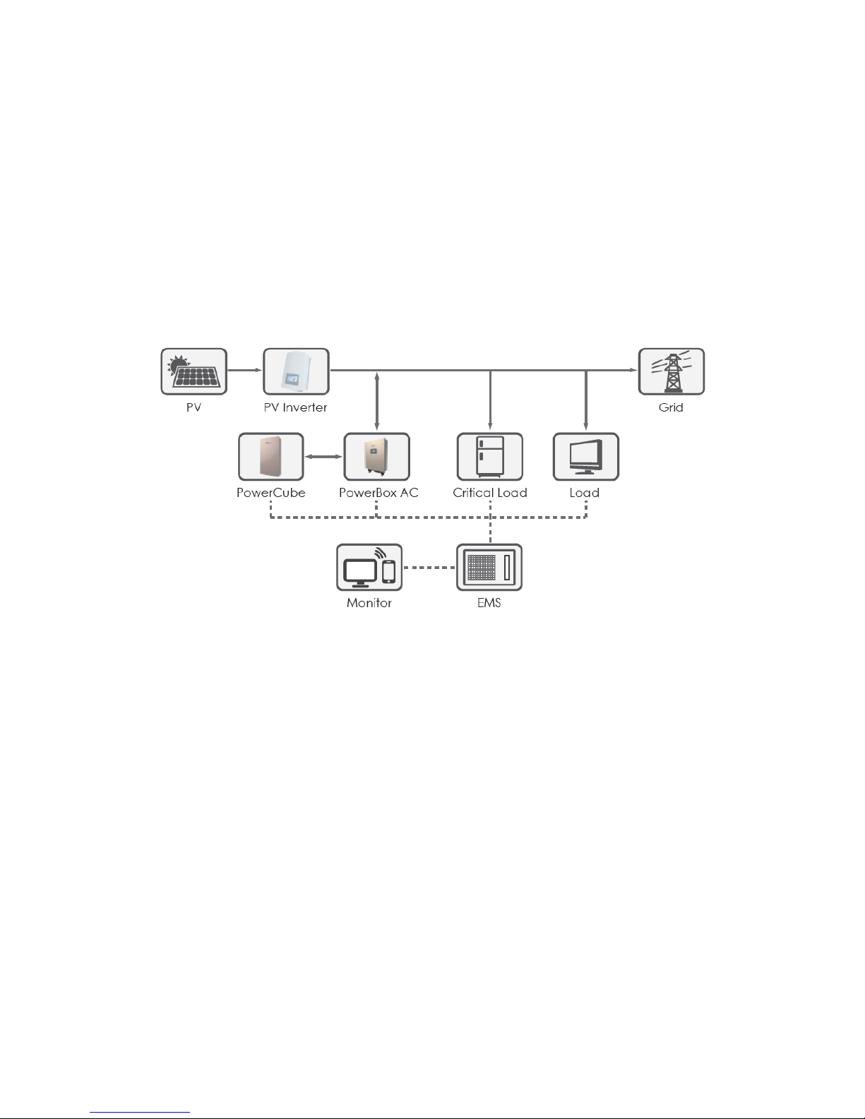
The POWER BOX is mainly applied and developed for the renewable energy
generation system compatible with lead-acid batteries and lithium-ion batteries. It
helps to achieve the optimal usage of renewable energy. The POWER BOX can
control the bi-directional flow of electric power, work under the auto / manual
mode and time-of-use (TOU) price mode, automatically controls the PowerCube
2.0 charge / discharge. The POWER BOX control features will store renewable
energy as well as grid power in PowerCube 2.0 & discharge the PowerCube 2.0 to
supply power to the load.
Fig. 1 POWER BOX Storage System Solution
2.Equipment Safety Notes
Before the inverter is used, please read all instructions, warning signs and this
manual. The inverter strictly meets safety rules of design and testing. Operators
should abide by safety regulations during installation, operation and
maintenance. Any improper operation may cause an electric shock or damage
the equipment and properties.

2.1 Safety Signs
2.2 Safety Notes
Electrical installation and maintenance must be carried out by competent
electricians according to national connection rules.
The POWER BOX must be installed only by qualified technical personnel, and
only after receiving appropriate approvals, as required by the local authority
having jurisdiction.
The PowerCube 2.0 should keep a certain distance with the POWER BOX and
protected well to prevent from any collision.
It is forbidden to place explosives and combustibles, e.g. gasoline, kerosene,
oil, slab, cotton and rag, etc. around the POWER BOX.
To avoid electric shock, the input of PowerCube 2.0 and AC output of the
inverter should be shut down for at least 5min. before installation or
maintenance.
The temperature of some parts of the inverter may exceed 60℃. The inverter
shall be cooled down in order to avoid getting burnt during the maintenance.
Children should not go near the inverter.
Please do not open the external cover of the inverter without permission,
except for installation/maintenance. Without following proper
installation/maintenance procedures, someone could be injured and/or even
damage the inverter.

Static power may damage electronic elements. Please neutralize the static
first to avoid damage to the inverter which could void warranty.
The warranty may be void if the equipment is damaged because it is not
operated according to the operation method of the specified manufacturer.
To completely isolate the inverter: - The first step is to shut down the DC switch
and followed by disconnecting the PowerCube 2.0 and the AC terminal.
The POWER BOX shall be isolated and shut down completely before
conducting any maintenance. The inverter must not be maintained in any
other modes!
It is FORBIDDEN to disconnect the PowerCube 2.0 terminal and the AC
terminal when the POWER BOX is running.
2.3 PowerCube 2.0 Installation and Maintenance
Notes
PowerCube 2.0 has been charged before delivery and should therefore be
prevented from short circuit during transportation and installation.
PowerCube 2.0 shall be placed in a well-ventilated space. Do not install the
PowerCube 2.0 in airtight or badly ventilated spaces.
Do not place the PowerCube 2.0 in high-temperature situations, direct
sunshine or in front of a furnace or fire to prevent PowerCube 2.0 from circuit
leakage causing fire and/or explosion.
The connection cable shall be as short as possible to avoid significant voltage
drop.
Before connecting the terminal for PowerCube 2.0 system, check the anode
and cathode of the PowerCube 2.0 system to ensure correct installation.
If it becomes necessary to store PowerCube 2.0, the system needs to be
isolated from the DC terminal and be disconnected from Power Box and load.
It should be stored away in a cool, dry and ventilated environment.
Please take precaution when conducting the following:
The maintenance operators shall have the know-how and technical skill for
the maintenance of the PowerCube 2.0;
When the battery is changed, the battery of the same model and quantity
shall be changed. It may be necessary to switch out the entire array of
batteries to avoid significant battery system loss due to mismatch;

Warning: Do not dispose the scrap batteries directly to fire. Such disposal may
cause the batteries to explode.
Warning: Do not dismantle the PowerCube 2.0. Its electrolyte may be toxic
and direct contact could cause serious irritation to skin and eyes and/or
worse personal injuries.
Warning: PowerCube 2.0 may cause an electric shock or short circuit when
mishandled. Please take the following measures before and during operation
of PowerCube 2.0:
a) Do not wear watch, ring or any other metal objects.
b) Use tools with insulated handles.
c) Wear rubber gloves and shoes.
d) Do not put tools and metals above the PowerCube 2.0.
e) Switch off the power supply mode before the PowerCube 2.0 terminal is
connected.
f) Ensure PowerCube 2.0 is not installed too close to the ground or connecting
components like cables and terminals touches or installed too close to the
ground. Having the system or connecting components too close to the
ground may cause trip over or accidental pull off disconnections causing
electric shock!
3.Installation
3.1 Product Overview
The inverter is checked strictly before being packed and delivered. It is forbidden
to put it upside down position during delivery.
Please check the product package and internal components carefully before
installation, e.g. housing, display and DC connection terminals.
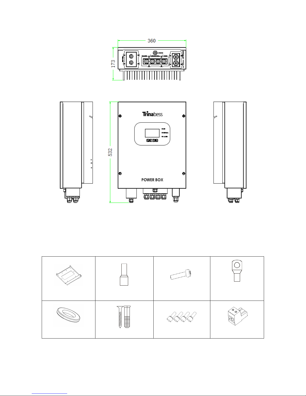
Fig. 2 POWER BOX Overview
3.2 Packing List
Before installation, please inspect the unit. Make sure nothing inside the package
is damaged. You should have received the following items inside the package:
Mounting Bracket×1
AC terminal×6
M5 screw×2
PowerCube 2.0
terminal×2
M6 flat washer×8
Wall plug & Screw ×8
Terminal cap×4
CT terminal×2

Current Transformer×2
User Manual×1
Warranty card×1
Quality Certificate×1
communication line×1
AC contactor×1
RS485s terminal×2
Fig. 3 Accessories of POWER BOX
3.3 Installation Environment
Please ensure a clean, tidy and dry environment during installation.
Ambient temperature scope:-25℃~60℃.
Relative humidity: 0~100 %(non-condensed).
The POWER BOX shall be installed in the place with an independent air
inlet and outlet channels.
There is neither inflammable nor explosive around.
The POWER BOX shall be connected to the power grid with an
over-voltage of CAT III and CAT II.
The maximum working condition altitude is 2000m.
Please consult our engineers about detailed requirements for installation
when in doubt.
3.4 Installation Tools
The following tools shall be prepared before installation:
No.
Tool
Model
Function
1
Hammer drill
Recommend drill dia.6mm
Drill holes on the wall

2
Screwdriver
Wiring
3
Wire stripper
Strip wire
4
4mm Allen Wrench
Turn the screw to connect
rear panel with inverter
5
Crimping tools
Crimp power cables
6
Multi-meter
Check grounding
7
Marker pen
Mark signs
8
Measuring tape
Measure distances
9
Level
Ensure that the rear panel is
properly installed
10
ESD gloves
Operators wear
11
Safety goggles
Operators wear
12
Anti-dust respirator
Operators wear

3.5 Installation Position
The POWER BOX should be vertically mounted (to ensure proper heat dissipation),
please choose a position without direct sunlight / snow accumulation to install the
POWER BOX.
Fig. 4 Installation Position of POWER BOX
3.6 Mounting
Step 1: Put the mounting bracket on the wall and mark the 8 drill holes by using a
marker pen. Drill 8 holes (drill bit 6mm) on the wall.
Step 2: Insert the wall plug vertically into the hole, note the insertion depth. (Not
too shallow or too deep)
Step 3: Fix the mounting bracket on the wall by using screws & flat washers.
Step 4: Put the POWER BOX on the mounting bracket.
Step 5: Ground the POWER BOX by using the grounding hole on the heat sink.
Step 6: OPTIONAL: you can lock the POWER BOX

4.Electrical Connection
Be aware of electric shock and chemical hazards!
Before connecting the PowerCube 2.0, ensure the cable connectors have
the correct polarity. Reversed polarity will damage the inverter!
Before connecting the PowerCube 2.0, please make sure that the
PowerCube 2.0 isolator is off; ensure the inverter can be disconnected
securely during maintenance.
Before connecting to Grid, please install a separate AC breaker (20A)
between POWER BOX and grid. A double pole AC breaker will be required to
connect critical load to the POWER BOX as well.
It is very important for system safety and efficient operation to use appropriate
cable for electrical connection.
PowerCube 2.0 connection: cable of AWG8 (10mm2) or AWG6 (16mm2).
Grid & Load connection: cable of AWG12 (4mm2).
Make sure N wire is connected to PE wire when the POWER BOX is working in
EPS (Emergency Power Supply) mode.
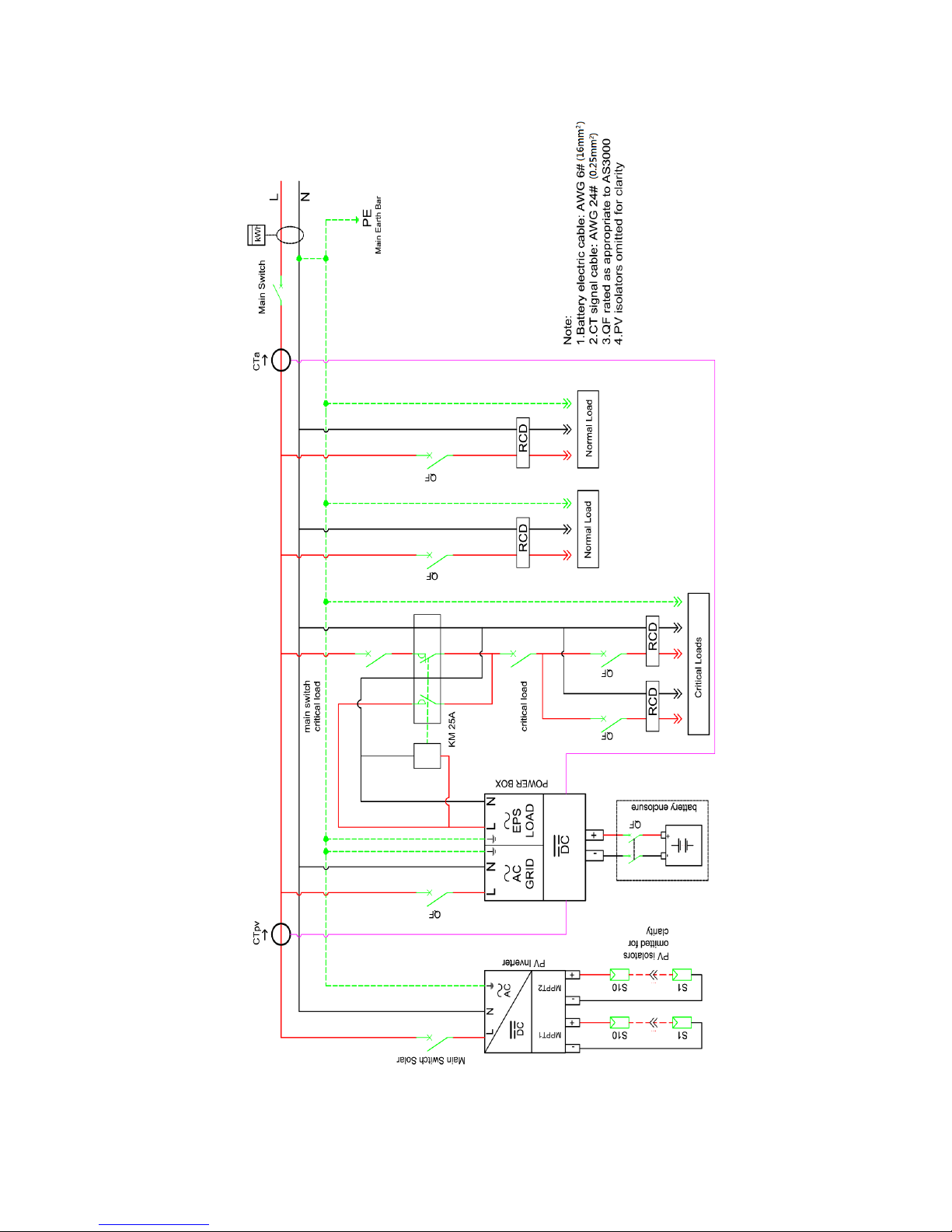
Fig. 5 Wiring Schematic of Single Phase System

4.1 PowerCube 2.0 Connection
Fig. 6 PowerCube 2.0 connection (Test PowerCube 2.0 wires polarity before
connection)
Step 1: Loosen 4 screws (A) using a screwdriver (fig. 6);
Step 2: Remove the waterproof cover (B), loosen the cable gland (C), and then
remove the stopper (G);
Step 3: Route the PowerCube 2.0 wires (F) through the cable gland, then connect
PowerCube 2.0 wires using crimp ring terminal (E);
Step 4: Fasten the waterproof cover using 4 screws.
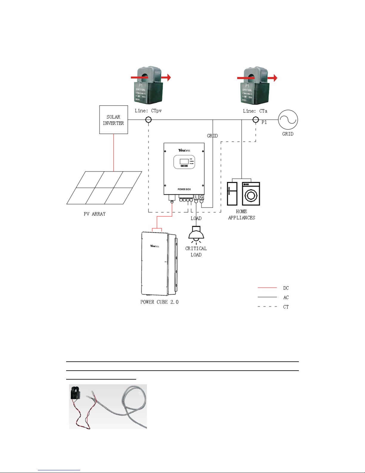
4.2 CT / RS485 connection
Fig. 7 Single Line Diagram (POWER BOX: energy storage add-on to existing
renewable system)
Step 1: Use network cable & terminal cap to extend the CT wire. (Network cable is
not provided)
NOTE: The recommended maximum distance for the CT wire is 5 meters. For longer
distance, it is advised to conduct necessary tests and ensure signal does not get
distorted prior installing.
Load
Grid
CTa
PV
Load
Main
CTpv

Fig. 8 Example of CT wire extension / Direction of CTa
CT wire
Extension cable (network cable)
POWER BOX
Red
Orange / white orange / brown / white brown
CT+
Black
Green / white green / blue / white blue
CT-
Table 1 CT connection
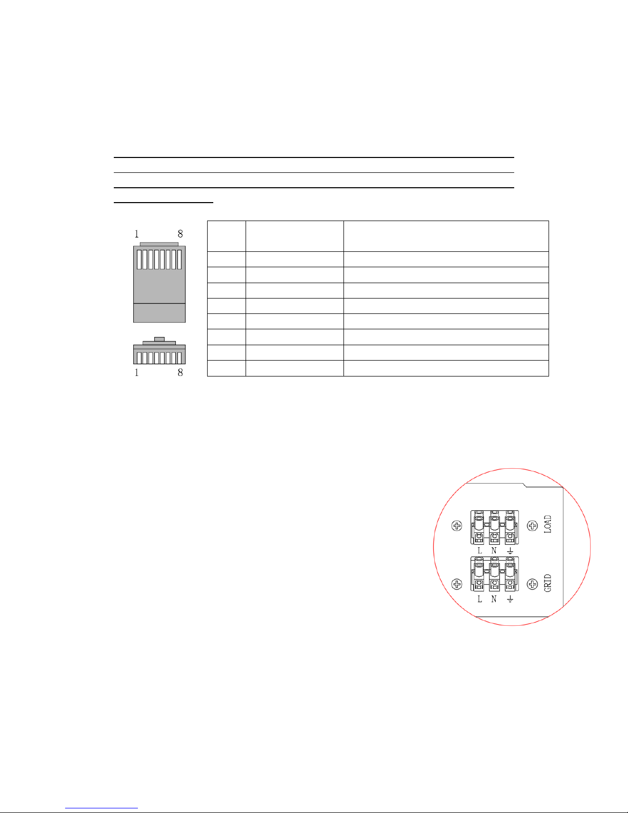
Fig. 9 CT / RS485 connection
Step 2: Loosen 4 screws (part A) using a screwdriver (fig. 6)
Step 3: Remove the waterproof cover (part B), loosen the cable gland (part C),
then remove the stopper (part G)
Step 4: Route CT cable through the cable gland, connect CT cable to CT terminal,
CT Sensor
(Direction = arrow point to the grid)
Main Switch
then insert CT terminal into corresponding ports. (Table 1)
Step 5: Route RS485 network cable through the cable gland, connect RS485
network cable to RJ45 connector and then insert the RJ45 connector into RS485m
port. (Fig. 9)
NOTE: A 2 meter long RS485m communication cable (between the powerbox to
the powercube) is supplied with the powerbox. However, if the cable need to be
extended, follow the table below to make a custom cable. The recommended
distance is 5 meters.
Table 2 RS485m connection
Step 6: Fasten the waterproof cover using 4 screws.
Note: NTC wire is not required to be connected.
4.3 Grid Connection
For most of the customers, please ONLY connect the GRID
port.
Please leave LOAD port unconnected.
Step 1: Loosen 4 screws (part A) using a screwdriver (fig. 10)
Step 2: Remove the waterproof cover (part B), loosen the
cable gland (part C), then remove the stopper (part G)
Step 3: Route 3-core cable through GRID cable gland, then
connect 3 wires to corresponding terminal blocks. (BROWN –L, BLUE –N,
YELLOW/GREEN –PE)
Step 4: Fasten the waterproof cover using 4 screws.
Pin
POWER BOX
485M
PACK
(BMS firmware should be B62 or newer)
1
Not Connect
RS485B
2
Not Connect
RS485A
3
Not Connect
Not Connect
4
RS485B
Not Connect
5
RS485A
Not Connect
6
Not Connect
Not Connect
7
Not Connect
RS485A
8
Not Connect
RS485B

Fig. 10 Grid & Load connection
4.4 Load Connection
Critical load: in case of grid outage, the POWER BOX will work in EPS (Emergency
Power Supply) mode, discharge the PowerCube 2.0 & supply power to critical
load via LOAD port.
LOAD port is only for critical load connection. Please make sure that you’ve
purchased the AC contactor accessory from Trinabess .
The connection procedure to LOAD port is the same as grid connection (Fig. 10).
Before connecting the critical load, please make sure that you understand the
following diagram (Fig. 11).
Fig. 11 Connection of critical load (AC contactor: 2 Normally Closed, 2 Normally
Open)
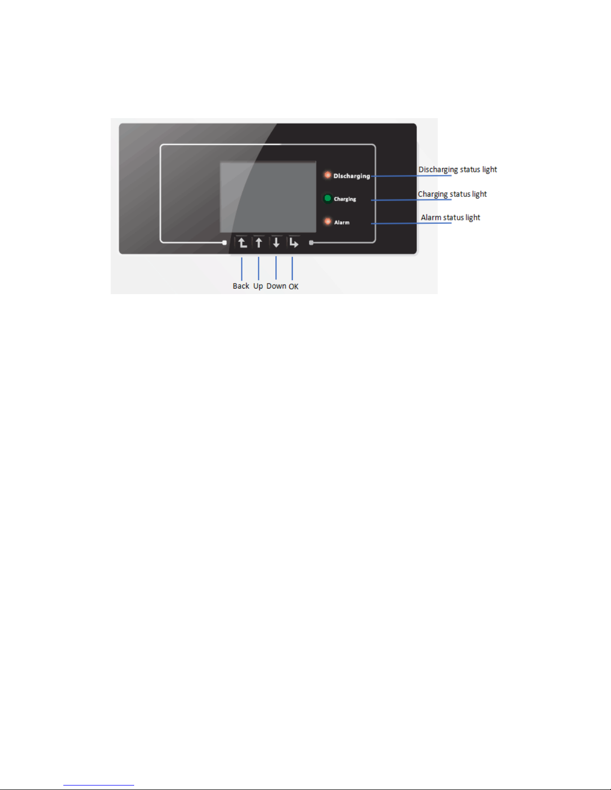
5.Indicators and Keys
Buttons:
press “Back” to the previous screen or enter the main interface;
press “Up” to the upper menu option or value plus 1;
press “Down” to the lower menu option or value minus 1;
Press “OK” to select the current menu option or switch to the next digit.
LED lights:
Discharging status Light(Green)
Discharging light flashing: system check before discharging the
PowerCube 2.0
Discharging light ON: discharging the PowerCube 2.0
Discharging light OFF: system is faulty (fault, or permanent)
Charging status Light(Green)
Charging light flashing: system check before charging the PowerCube 2.0
Charging light ON: charging the PowerCube 2.0
Charging light OFF: system is faulty (fault, or permanent)
Alarm light(Red)
Alarm light ON: system is fault (fault, or permanent)
Table of contents
Other Trinabess Inverter manuals


