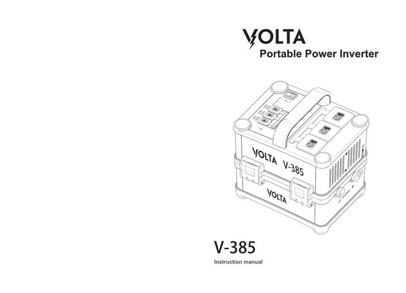
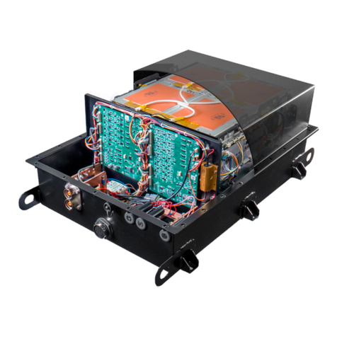
VOLTA FLEX SYSTEM User manual

Volta Power Systems
FLEX SYSTEM
User Manual


©2023 Volta Power Systems, LLC
The intellectual property contained in this manual is owned or licensed to Volta
Power Systems, LLC and is protected by applicable copyright and trademark law.
This material may not be copied, modified, translated, or reproduced without the
prior written permission of Volta Power Systems.
This manual represents a range of Volta Power Systems equipment. Some of
the systems or equipment described in this manual may not be available for
the specific OEM application. Descriptions, graphics, photos, and specifications
were correct at the time of publication. Volta Power Systems reserves the right
to update or change equipment and products without obligation to provide,
install, or modify the equipment for the OEM application.
.

VPS-DOS-TR-04-E / Rev 05
26-July-2023
Volta Power Systems Page 4 of 40
TABLE OF CONTENTS
Welcome to Volta . . . . . . . . . . . . . . . . . . . . . . . . . . . . . . . . . . 6
Freedom to Roam . . . . . . . . . . . . . . . . . . . . . . . . . . . . . . . . . . . . 6
Quiet and Clean . . . . . . . . . . . . . . . . . . . . . . . . . . . . . . . . . . . . . . 6
More Power . . . . . . . . . . . . . . . . . . . . . . . . . . . . . . . . . . . . . . . . . 6
More Confidence . . . . . . . . . . . . . . . . . . . . . . . . . . . . . . . . . . . . . 6
More Safety . . . . . . . . . . . . . . . . . . . . . . . . . . . . . . . . . . . . . . . . . 6
Quick Start . . . . . . . . . . . . . . . . . . . . . . . . . . . . . . . . . . . . . . 7
Turning On Your Volta System . . . . . . . . . . . . . . . . . . . . . . . . . . . . 7
Turning Off Your Volta System . . . . . . . . . . . . . . . . . . . . . . . . . . . . 7
Using the Touchscreen . . . . . . . . . . . . . . . . . . . . . . . . . . . . . . . . . 7
Introduction. . . . . . . . . . . . . . . . . . . . . . . . . . . . . . . . . . . . . . 8
About Volta Power Systems . . . . . . . . . . . . . . . . . . . . . . . . . . . . . . 8
Service and Contacting Volta Power Systems . . . . . . . . . . . . . . . . . . 8
Return Policy . . . . . . . . . . . . . . . . . . . . . . . . . . . . . . . . . . . . . . . . 8
Definitions . . . . . . . . . . . . . . . . . . . . . . . . . . . . . . . . . . . . . . . . . . 8
System Maintenance . . . . . . . . . . . . . . . . . . . . . . . . . . . . . . . . . . 9
Integrating Additional Components into the Volta System. . . . . . . . . 9
Safety . . . . . . . . . . . . . . . . . . . . . . . . . . . . . . . . . . . . . . . . . . 11
Warnings. . . . . . . . . . . . . . . . . . . . . . . . . . . . . . . . . . . . . . . . . . . 11
Safety Guidelines . . . . . . . . . . . . . . . . . . . . . . . . . . . . . . . . . . . . . 11
Volta System Overview . . . . . . . . . . . . . . . . . . . . . . . . . . . . . . . 13
Flex Battery Management System . . . . . . . . . . . . . . . . . . . . . . . . . 14
Volta System Components. . . . . . . . . . . . . . . . . . . . . . . . . . . . . . . 14
Temperature Limits . . . . . . . . . . . . . . . . . . . . . . . . . . . . . . . . . . . 16
Volta System On/Off Pushbutton Overview . . . . . . . . . . . . . . . . . . 17
Turning On the Volta System . . . . . . . . . . . . . . . . . . . . . . . . . . . . . 17
Turning Off the Volta System . . . . . . . . . . . . . . . . . . . . . . . . . . . . . 17
Shore Power Mode . . . . . . . . . . . . . . . . . . . . . . . . . . . . . . . . . . . . 17
Pushbutton LED Indicators . . . . . . . . . . . . . . . . . . . . . . . . . . . . . . 18
Touchscreen Overview . . . . . . . . . . . . . . . . . . . . . . . . . . . . . . . 19
Home Screen. . . . . . . . . . . . . . . . . . . . . . . . . . . . . . . . . . . . . . . . 19
Alerts Screen . . . . . . . . . . . . . . . . . . . . . . . . . . . . . . . . . . . . . . . . 21
Settings Screen . . . . . . . . . . . . . . . . . . . . . . . . . . . . . . . . . . . . . . 22
Inverter Screen. . . . . . . . . . . . . . . . . . . . . . . . . . . . . . . . . . . . . . . 23
State of Charge (SOC) Gauge . . . . . . . . . . . . . . . . . . . . . . . . . . 24
SOC Overview . . . . . . . . . . . . . . . . . . . . . . . . . . . . . . . . . . . . . . . 24
SOC Gauge Flash Codes . . . . . . . . . . . . . . . . . . . . . . . . . . . . . . . . 24
Charging the System and Increasing System Runtime . . . . . . . . . . 25
System Runtime. . . . . . . . . . . . . . . . . . . . . . . . . . . . . . . . . . . . . . 25
Charging via Shore Power . . . . . . . . . . . . . . . . . . . . . . . . . . . . . . . 25
Charging via the Secondary Alternator . . . . . . . . . . . . . . . . . . . . . . 26
Charging via Solar Power. . . . . . . . . . . . . . . . . . . . . . . . . . . . . . . . 26
Charging via Generator . . . . . . . . . . . . . . . . . . . . . . . . . . . . . . . . . 26
Recovery from Zero State-of-Charge . . . . . . . . . . . . . . . . . . . . . . . . 27
Using the Auto Start System . . . . . . . . . . . . . . . . . . . . . . . . . . 28
Auto Start System Overview. . . . . . . . . . . . . . . . . . . . . . . . . . . . . . 28
Storing Vehicles with a Volta System . . . . . . . . . . . . . . . . . . . . . 29

VPS-DOS-TR-04-E / Rev 05
26-July-2023
Volta Power Systems Page 5 of 40
Long Term Storage (Greater than 3 Months). . . . . . . . . . . . . . . . . . . . . 29
Short Term Storage (Less than 3 Months). . . . . . . . . . . . . . . . . . . . . . . 29
Using the Volta System in Hot and Cold Temperatures. . . . . . . . . . . . . 31
High Temperature Operation . . . . . . . . . . . . . . . . . . . . . . . . . . . . . . . 31
Cold Temperature Operation . . . . . . . . . . . . . . . . . . . . . . . . . . . . . . . 31
Installing MyVolta Bluetooth Module . . . . . . . . . . . . . . . . . . . . . . . 34
MyVolta App . . . . . . . . . . . . . . . . . . . . . . . . . . . . . . . . . . . . . . . . . . 36
Troubleshooting and FAQs . . . . . . . . . . . . . . . . . . . . . . . . . . . . . 37
How long will my Volta System run? . . . . . . . . . . . . . . . . . . . . . . . . . . 37
What’s new on Flex Pack compared to past Volta Systems? . . . . . . . . . . 37
Why is there a system delay after I press the On/Off pushbutton? . . . . . . 37
Why won’t my Volta System charge? . . . . . . . . . . . . . . . . . . . . . . . . . 37
How can I tell if my solar panels are working?. . . . . . . . . . . . . . . . . . . . 38
Does the Volta System have to be turned on when charging? . . . . . . . . 38
Why can’t I connect my phone to my Volta System? . . . . . . . . . . . . . . . 38
When do I need to adjust the selected charge rate? How do I adjust the
charge rate?. . . . . . . . . . . . . . . . . . . . . . . . . . . . . . . . . . . . . . . . . . . 39
How do I dim my pushbutton LED? . . . . . . . . . . . . . . . . . . . . . . . . . . 39

VPS-DOS-TR-04-E / Rev 05
26-July-2023
Volta Power Systems Page 6 of 40
WELCOME TO VOLTA
Experience camping like you’ve only dreamed of. Volta’s automotive-grade,
advanced energy storage systems deliver a true off-grid adventure without
sacrificing the comforts of home.
Freedom to Roam
Gain access to REAL off-grid capability without sacrificing the amenities you
want. Volta Systems provide all the power you need including all-night air
conditioning with none of the noise or emissions of a generator.
Quiet and Clean
Ditch the loud, smelly generator and choose clean, high-performance power
instead. Gain access to pristine wilderness without disrupting it with fumes and
noise. Unlike generators, our environmentally-conscious power systems charge
from solar, shore, or while you drive, using otherwise wasted energy. Leave no
trace with a Volta System.
More Power
Experience all the power you need. Volta Systems leverage the highest energy
density on the market to deliver more power in less space and with less weight.
Run 110V appliances simultaneously, including air conditioning, all day or over-
night. Take the comforts of home on the road without having to compromise.
More Condence
Built on the same automotive-grade technology that powers electric vehicles,
Volta Systems are easy to use, virtually maintenance free, and will last the
lifetime of your vehicle.
More Safety
Protected by seven layers of safety, our systems are engineered and tested
to meet rigorous auto-industry standards, ensuring a system that’s safe and
dependable for your whole family.

VPS-DOS-TR-04-E / Rev 05
26-July-2023
Volta Power Systems Page 7 of 40
QUICK START
Turning On Your Volta System
To turn your system on, simply press the Volta Pushbutton. After a few seconds
of system checks, the ON/OFF button and Touchscreen lights up.
Turning Off Your Volta System
To turn your Volta system off, press and release the power button, then allow the
system a few seconds to power off. After it’s powered down, the touchscreen and
button will go dark.
Using the Touchscreen
Monitor the State-of-Charge (SOC) and control the Volta System via the touch-
screen.
The touchscreen turns on a few seconds after the pushbutton is pressed, a
charge source is sensed, or the vehicle is turned on.

VPS-DOS-TR-04-E / Rev 05
26-July-2023
Volta Power Systems Page 8 of 40
INTRODUCTION
About Volta Power Systems
Volta Power Systems provides exclusive access to safe, powerful, and simple
energy solutions built with the latest in automotive-grade lithium-ion technolo-
gy. RV OEMs trust Volta to deliver advanced power systems that meet environ-
mental goals, drive profitability, and enhance end-user experiences like no other
system can.
Service and Contacting Volta Power Systems
Warning: Servicing instructions are for use by qualified personnel only.
To minimize the risk of electrical shock, do not perform any servicing
beyond what is specified in the operating instructions unless you are
qualified to do so. Any unauthorized attempt to service the system may
result in damage to the system, voiding of the warranty, and potential
injury.
Except for extended periods of storage, no specific maintenance is required for
the service life of the Flex Pack. In the event the Flex Pack has a breach of con-
tainer integrity or has been submitted to abusive operating conditions (crush,
short circuit, overcharge, over-discharge, submersion, evidence of combustion,
exposure to fire, etc.), please contact your authorized Volta representative.
Phone support is available during normal business hours. Visit the Volta Power
systems website for additional troubleshooting, Frequently Asked Questions,
and instructional videos.
Phone: (616) – 226 – 4222
Web: www.VoltaPowerSystems.com
Return Policy
Returns are specific to the warranty terms and conditions of purchase.
Denitions
Term Definition
Volta System The general term for the complete Volta energy
system solution and its power distribution devices.
Flex Pack Volta’s second generation energy storage pack,
composed of electrochemical lithium-ion cells.
Power Distribution
Hub
The Flex Power Distribution Hub (PDH) encases the
Flex System’s required power distribution components
in a compact design, making installation and connec-
tions simpler.
End User The owner/operator of the product into which a Volta
System is integrated.

VPS-DOS-TR-04-E / Rev 05
26-July-2023
Volta Power Systems Page 9 of 40
Term Definition
OEM The company/organization, its staff, its subcontractors,
or any other person working under its responsibility, its
control, or appointed by it that is in charge of testing,
using, or integrating the Volta System.
Volta Power Dis-
tribution Devices,
Components, or
Systems
These include but are not limited to the components
that comprise the Volta System, such as inverters,
chargers, and converters.
On/Off Pushbutton
or Volta Pushbut-
ton
Main system pushbutton that when pressed, turns on
the Volta System.
SOC State of Charge (SOC) indicates a percent of total pack
charge.
Touchscreen Main system display.
CAN Controller Area Network is a bus communication
system made for vehicle intercommunication. This bus
allows different types of devices to communicate with
each other in real time, without a host computer.
AWG American Wire Gauge: A standardized wire gauge
system.
Manufacturer
Documentation
Supplemental documentation from the original
manufacturer of components included in the Volta
System.
RVIA Recreational Vehicle Industry Association
120V or 120 VAC Synonymous with 110 VAC when referring to house-
hold appliances, devices, or outlets
System Maintenance
The Volta System and its components are maintenance free. However, depend-
ing on the integration of the Volta system, there may be components that are
recommended by the OEM or upfitter that may require regular maintenance.
For example, an OEM may recommend when to replace the belt on the second-
ary alternator. Refer to the OEM for recommended maintenance to ensure safe
operation.
Integrating Additional Components into the Volta System
Your Flex Pack is designed for connection and operation with Volta Power
Systems equipment or Volta Power Systems approved equipment. Using the
Flex Pack in other configurations may be unsafe and void the warranty. Opening
the Flex Pack housing also voids the warranty.
If you plan to integrate additional components not provided by Volta, like a 48V
air conditioning unit, contact Volta Power Systems and provide the component’s

VPS-DOS-TR-04-E / Rev 05
26-July-2023
Volta Power Systems Page 10 of 40
documentation or specifications. This allows Volta to assess if the component
can safely integrate with the system. Volta may provide the appropriate interface
or connection for your existing Volta harness.
Volta’s assessment of these components are essential for the safe, reliable
operation of the Volta System as well as the personal safety of the individual
carrying out the work. It is the vehicle owner’s responsibility to make sure that
any equipment fitted complies with appropriate standards.
Any additional components of the Volta System shall:
•Ensure proper connections and circuit protection devices that meet
component requirements and the ANSI/RVIA LV standard for Low
Voltage Systems.
•Provide adequate support and strain relief for all connections.
•Confirm the component can be enabled/disabled by the Battery
Management System.

VPS-DOS-TR-04-E / Rev 05
26-July-2023
Volta Power Systems Page 11 of 40
SAFETY
The user is responsible for safe use of the Volta System and Volta Power Distribu-
tion Devices or Systems. Before using the Volta System, Volta recommends that
all users read this manual and fully understand all instructions.
Warnings
The following symbol is used to denote a safety critical instruction or informa-
tional detail, which if not followed or fully understood, could result in death,
serious injury, or voided warranty.
Safety Guidelines
The following guidelines must be adhered to and also applied/considered when
supplying any documentation to the end user.
Warning: Misusing a Flex Pack may result in damage, loss of product,
and serious injury. Make sure to follow the safety rules listed below:
–Never short-circuit the power terminals of a Flex Pack.
–Do not reverse the polarity, or mix positive and negative connec-
tions, of the Volta System or connected power distribution compo-
nents.
–Do not attempt to disable the Flex Pack safety devices or program-
ming.
–Do not disassemble the Flex Pack.
–Do not submerge the Flex Pack.
–Do not incinerate the Flex Pack.
–Do not use a Flex Pack without its Battery Management System
(BMS) fully functional.
–Do not subject a Flex Pack to excessive mechanical stresses beyond
its intended application.

VPS-DOS-TR-04-E / Rev 05
26-July-2023
Volta Power Systems Page 12 of 40
–Only use a Flex Pack in accordance with the guidelines set forth in
this manual.
–Do not operate the Volta System or its power distribution devices or
systems if the Flex Pack exhibits soot, scorching, or other evidence
of thermal excursion.
Warning: The Volta System is designed for connection and operation
with Volta power distribution devices, or equipment expressly approved
by Volta Power Systems. This ecosystem of approved devices is a layer
of safety within a Volta system. Use of other devices compromises this
layer of safety. Use of the Volta System with other external devices could
present a hazard and is expressly prohibited by Volta Power Systems.
Use of unapproved devices results in voiding of the Volta Power Systems
warranty.
Warning: Do not place a Flex Pack on, in, or near fires, or other high-tem-
perature locations greater than 140°F (60°C). This includes intensive
sunlight. Doing so may cause the Flex Pack to overheat and may result
in a loss of performance and/or a shortened life expectancy.
Warning: Read and understand this User Manual before proceeding to
un-crate, charge, install, or use the Volta System and Power Distribution
Hub.
Warning: Careless handling of electrical components can be fatal. Never
touch or use electrical components or appliances while feet are bare,
while hands are wet, while standing in water, or while on wet ground.
Warning: Always remove jewelry and wear appropriate personal protec-
tive equipment (PPE) before handling or operating the Volta Flex Pack
and Volta Power Distribution Devices or Systems.

VPS-DOS-TR-04-E / Rev 05
26-July-2023
Volta Power Systems Page 13 of 40
VOLTA SYSTEM OVERVIEW
The Volta System provides power to your vehicle’s electrical systems using safe,
powerful, and simple energy solutions built with the latest in automotive-grade
Lithium-Ion technology.
The appearance and availability of components in
your Volta System may vary from what is shown.
Charge from
Solar Panels
Charge from
Secondary
Alternator
Flex Pack
120VAC
Devices
12VDC or
24VDC
Devices
DC-DC
Converter
Inverter
Operate Devices and
Charge Pack from
Shore Power

VPS-DOS-TR-04-E / Rev 05
26-July-2023
Volta Power Systems Page 14 of 40
A Volta System typically contains an energy storage source (Flex Pack), an alter-
nator for charging during driving operations, an inverter/charger for shore power
charging and 120 VAC power distribution, and converters to create DC power at
various voltages. To simplify the installation process, certain power distribution
components may be combined into a Power Distribution Hub. Combining
elements into a centralized hub makes the system integration easier. Your
actual system may vary in size, complexity, power distribution devices used, or
other application specific variations.
The Volta System and power distribution systems are similar in complexity
to a vehicle engine or generator. Therefore, only Volta technicians or trained
professionals with in-depth knowledge of Volta Systems should service these
components.
Flex Battery Management System
The safety control logic within a Flex Pack is contained in a system controller
known as the Flex Battery Management System (BMS). The BMS optimizes pack
performance and protects the pack against extreme operating situations. The
BMS continually monitors pack performance, and in the case of abuse, neglect,
or failures, it will shut off Volta power distribution devices and/or energy to the
Flex Pack.
Information regarding the system, or pack status, is available from the Flex Pack
via CAN communication. This information can be viewed on an OEM display by
reading the CAN data stream. Contact your Volta representative for information
about connecting a Volta system to a non-Volta display. In the absence of a
display to read CAN data, the SOC gauge and pushbutton flash codes can assist
in diagnosing system operation if the BMS detects any issues with the pack or
system operation. Refer to “Pushbutton LED Indicators” on page 18 and
State-of-Charge (SOC) Flash Codes on page 20.
Volta System Components
Your Volta System may be configured with the following options:
•Flex Pack: The Flex Pack is the energy source for your Volta System. A
14-gauge steel housing protects the lithium-ion cells, and an internal
Battery Management System monitors the system, balances the cells,
and controls energy output.
•Inverter/Charger: The inverter changes the Flex Pack’s energy from
direct current (DC) into alternating current (AC) to power the vehicle’s
120V AC devices (air conditioner, heater, cook top, etc.). The inverter also
converts shore power (AC) to direct current (DC) for charging the Flex
Pack.
•DC-DC Converter: The DC-DC converter drops the Flex Pack’s energy
from 58V DC to power your vehicle’s 12V DC or 24V DC devices (vehicle
electronics, lights, refrigerator, etc.).
•Secondary Alternator: The high-powered, secondary alternator provides
charging power directly from your vehicle’s engine to the Flex Pack.
•Solar Controller: The solar controller regulates solar power input from

VPS-DOS-TR-04-E / Rev 05
26-July-2023
Volta Power Systems Page 15 of 40
external solar panels into a stable, usable form of energy to charge the
Flex Pack.
•On/Off Pushbutton: Press the On/Off pushbutton to turn on or off the
Volta System.
•Touchscreen: Use the Touchscreen to monitor and control the Volta
System.

VPS-DOS-TR-04-E / Rev 05
26-July-2023
Volta Power Systems Page 16 of 40
Temperature Limits
The Volta System is programmed with several operational temperature limits to
protect the pack and prolong its life.
F° C° Limit Description
140 60 Maximum
storage
temperature
Do not store the pack at or above this
temperature. Doing so may result in a loss of
performance and/or a shortened life expectan-
cy.
134.6 57 High tempera-
ture fault
Volta System shuts down and does not
function above this temperature.
131 55 High tempera-
ture warning
Volta System is near the high temperature
fault. SOC gauge may flash yellow or an
indicator may appear on the touchscreen.
125.6 52 High tem-
perature fault
recovery
If the pack reaches the high temperature fault
limit (134.6°F or 52°C), the Volta System will not
restart until it cools below this temperature.
116.6 47 Too hot to
charge
Above this temperature, the Volta System
powers devices, but the System will not charge,
even if connected to shore power.
109.4 43 Too hot to
charge recovery
If the pack reaches the too hot to charge
temperature (116.6°F or 47°C), the Volta System
will not allow charging again until it cools to
this temperature.
68 20 Heating control
off temperature
At this temperature, the pack heating control
turns off if previously on.
59 15 Heating control
on temperature
When the pack is below this temperature, the
pack heating control is on to actively warm the
pack.
42.8 6 Too cold to
charge recovery
If the pack reaches the too cold to charge
temperature (41°F or 5°C), the Volta System will
not allow charging again until it reaches this
temperature.
41 5Too cold to
charge tem-
perature
Below this temperature, the Volta System
powers devices, but the System will not charge,
even if connected to shore power.
-4 -20 Low tempera-
ture fault
Volta System shuts down and does not
function below this temperature.
-40 -40 Minimum
Storage
Temperature
Do not store the pack at or below this tem-
perature. Anything at or below this tempera-
ture will need to be parked or stored in climate
controlled storage.
The values listed in this table represent approximate values that may vary by
system specification, application, and environmental conditions.

VPS-DOS-TR-04-E / Rev 05
26-July-2023
Volta Power Systems Page 17 of 40
VOLTA SYSTEM ON/OFF PUSHBUTTON OVERVIEW
Turning On the Volta System
Press the On/Off pushbutton to turn on the Volta System and power your
vehicle’s electrical systems and devices. When the On/Off pushbutton is pressed
to turn on the Volta System, a 2 to 5 second system check occurs. If all systems
checks are successful, the Flex Pack’s internal contactor engages, supplying
power to all Volta components, turning on the Volta System.
Do not repeatedly press the pushbutton. After pressing the button, wait 30
seconds for all system checks to occur before pressing the button again.
Turning Off the Volta System
Press the On/Off pushbutton to turn off the Volta System. After pressing the
pushbutton to turn off the Volta System, a few seconds will pass before the
pushbutton LED turns off and the Touchscreen or SOC gauge shuts down,
signaling that the Volta System is turned off.
If the Volta System is off, and a charge source is detected, the Volta System
enters Charge Only Mode. Refer to Charge Only Mode below for additional
details.
Shore Power Mode
When in Shore Power Mode, the Pushbutton LED flashes green continuously.
To initiate Shore Power Mode:
•If the Volta System is off (no pushbutton LED indicator and the Touch-
screen or SOC Gauge is off), connect to an AC charge source or shore
power.
•If connected to an AC charge source or shorepower, press the Volta
Pushbutton. The Pushbutton LED will change from solid green to
continuous flashing green.
•Enter or exit Shore Power Mode by pressing the Volta Pushbutton
anytime you are connected to shore power.
Pushbutton

VPS-DOS-TR-04-E / Rev 05
26-July-2023
Volta Power Systems Page 18 of 40
In Shore Power Mode, the Flex Pack charges as necessary and maintains
optimal temperature for charging and discharging. Also, if shore power is lost,
the Volta System shuts down automatically. This mode is ideal for short term
storage, when preparing for a trip in cold weather, or for any scenario where
it is important for the system to shut down in case of shore power loss (power
outage, accidental unplugging, or if a breaker or GFCI trips).
Also, when in Shore Power Mode, the AC loads in your vehicle (air conditioner,
cooktop, outlets, etc.) are powered from the charge source. Exceeding the rated
capacity to the charge source may result in tripped breakers or load shedding.
Depending on your upfitter or OEM configuration, DC loads may or may not be
operational while in Shore Power Mode.
Pushbutton LED Indicators
The Pushbutton LED flash codes and colors communicate basic system and
fault states, including:
LED Color System Status
Green System on
Green Flashing Charge Only Mode - System turned
off and charge source connected
Yellow Too cold to charge
Yellow Flashing (5
seconds)
Volta System is starting after press-
ing the pushbutton
Dim Yellow Flashing (5
seconds)
Volta System is shutting down after
pressing the pushbutton
Yellow Flashing (30
seconds then system
shuts down)*
System fault causing shutdown. If
possible, monitor the touchscreen
before shutdown to assist in diag-
nosing the fault
* If a system fault is present and a charge source is connected, the
LED remains dim yellow after blinking yellow for 30 seconds.

VPS-DOS-TR-04-E / Rev 05
26-July-2023
Volta Power Systems Page 19 of 40
TOUCHSCREEN OVERVIEW
Monitor and control the Volta System via the touchscreen. The appearance and
availability of touchscreen features on your Volta System may vary from what is
shown.
The touchscreen turns on a few seconds after the pushbutton is pressed, a
charge source is sensed, or the vehicle is turned on.
Home Screen
F
G
C
D
B
AE
A) State-of-Charge Gauge (SOC): Displays the approximate SOC of the
Flex Pack. The SOC gauge’s flash codes and colors communicate basic
system and fault states. Refer to State-of-Charge (SOC) Flash Codes on
page 20.
B) Charge Time Remaining: Displays the approximate charge time re-
maining in the Flex Pack. This value changes depending on the amount
of load applied to the pack. For more information on increasing the
system runtime, refer to “Charging the System and Increasing System
Runtime” on page 25.
C) Current Time: Displays the current time.
D) Menu Bar: Touch the menu bar buttons to access the corresponding
screens, including:
Alerts button: Refer to “Alerts Screen” on page 21.
Settings button: Refer to “Settings Screen” on page 22.

VPS-DOS-TR-04-E / Rev 05
26-July-2023
Volta Power Systems Page 20 of 40
Inverter button: Refer to “Inverter Screen” on page 23.
Sleep button: Press to put the Touchscreen to sleep. Touch
the screen to turn it back on.
Home button: Access the Home screen.
E) System Indicators: Appear to communicate system changes or status-
es, including:
Alternator Charging: Flex Pack is ready for charging from
alternator, or is currently charging from alternator.
Flex Pack Temperature Low: Flex Pack is too cold to charge.
Heating Pads On: Heating pads are on and actively warming
the Flex Pack.
Pack Temperature High: Flex Pack is at or near the high
temperature shutdown limit.
System Fault: System fault is active. Refer to the Alerts screen
for details.
F) Pack Temp: Displays the current temperature of the Flex Pack.
G) Power Flow: Displays the power consumption (negative value) on the
Flex Pack or the rate of charge (positive value) to the Flex Pack.
Table of contents
Other VOLTA Inverter manuals
Popular Inverter manuals by other brands

Westerbeke
Westerbeke 8.0 KW BCGTC - 50 Hz Operator's manual

Solutronic
Solutronic SolBattHome 5.0 Li user manual

Lenze
Lenze i550 Series Project planning manual

SOLIS
SOLIS Solis-EPM3-5G-Plus Quick installation instructions

ACPro
ACPro A Series Service manual

Control Techniques
Control Techniques FXM5 user guide