novotechnik MUP-410 User manual

2 Connection
1 Description
12 1413
EXT. 1
EXT. 2
+
-
-
+
3 4 5
1 2
+
Power supply
V
Analog
output
mA
79
8
OMNI
0,05…2,5 mm2
3 0 …12 A WG
8
0.32
Ø 3,5 mm
Ø 0.14 in
1,5 Nm
13.2 lb-in
MINI-TECHDOK - MUP-410_AO - 2023.1.7 - en
www.novotechnik.de 1 / 4
fr it
Digital DIN rail mounted signal
converter
INPUT FOR POTENTIOMETERS
• Input for potentiometers
• Analog output
• Up to 7 200 measurements/s
• Quick conguration by DIP switch
• PC congurable via USB port
• Galvanic isolation 2.5 kVAC
• Simple instalation to DIN rail
csesen fr
MUP-410
Lo
Hi
1
2
4
3
1
USB
micro
1 2 3 4 5 7 8 9
Power
IN 1 OUT 1
Input
Pot.
mA
V
OMNI
LED Indication
Hi Lo Status
Device is running
Device functionality is limited, powered via USB
This device has a Delayed Start option
Error: device is out of order
Tare function is activated
Error: of input (> ±110% of range) or of sensor
[ERR.1, 3]
Error: AO loop open [ERR.10]
Error: setting / calibration [ERR.34-36]
Serious error (Safe mode) [ERR.50]
Button function is blocked
Simulation mode is activated
Legend
1
Connectors
2
Control button
3
RGB Status LED
Note
Contactors, high power electric motors, frequency drives and other power devices
should not be in a close proximity of the meter. Input signal leads (measured value)
should be seperated from all power lines and power devices. Even though the device
has been designed and tested according to standards for industrial environment, we
strongly advise to adhere to the above presented rules.
DANGER WARNING
HAZARD OF ELECTRICAL SHOCK
- Disconnect all power and other supply lines before servicing equipment
EQUIPMENT OPERATION HAZARD
- Do not use this product in safety critical system
- Do not disassemble, repair or modify this product
- Do not operate beyond the recommended operating environment
Failure to follow this instruction may result in death or serious injury. Failure to follow these instructions may result in death, serious injury, or equipment damage.
Electrical equipment should be installed, operated, serviced, and maintained only by qualified personnel.
No responsibility is assumed by Novotechnik Messwertaufnehmer OHG for any consequences arising out of the use of this device.
de

3
Device setting
Input wiring diagram
Analog output
0…5 /20 mA
4…20 mA
3 - 4
0…2 /5/10 V
±10 V
3 - 5
Input - Potentiometers
iControl of external inputs is via contact
(voltage-free)
Analog current output [mA]
Lo
Hi
1 2 3 4 5 7 8 9
Lo
Hi
1 2 3 4 5
mA
7 8 9
+−
Analog Voltage Output [V]
Lo
Hi
1 2 3 4 5
V
7 8 9
+−
Input - External inputs
12 13 14
Ext. 1
Ext. 2
Output wiring diagram
Analog input range setting (Teach-IN)
1. Enter the teach-IN mode by a short press of the Lo button - LED Hi yellow and LED Lo turquoise
2. Put the connected sensor in the position that shall have minimum output (RNG.MIN)
3. Set the minimum output value by a long press (> 2 s) of the Lo button - LED Hi yellow, LED Lo purple
4. Put the connected sensor in the position that shall have maximum output (RNG.MAX.)
5. Set the maximum output value by a long press (> 2 s) of the Lo button - LED Hi yellow, LED Lo green
6. Leave teach-IN mode by a short press of the Lo button and return to the standard working mode - LED Hi green
The teached measuring range is non volatile and retained even after power off/on
DIP switch
For a quick set up you can use the DIP switch. Changing a configuration only takes effect after power off/on.
Zero settings (Tare)
1. Enter the tare mode by a short press of the Hi button - LED Hi white and LED Lo turquoise
2. Put the connected sensor in the position where the tare function shall be executed
3. Set the tare by a long press (> 2 s) of the Hi button - LED Hi white, LED Lo green
4. Leave tare mode by a short press of the Hi button - LED Hi green, LED Lo white
i The teach-IN or tare mode is terminated
immedeately and without storage by a short press
of Lo or Hi buttons or 1 minute of inactivity.
i Setting of Analog input TEACH-IN is active only
when DIP switches No. 1-2 are in the “0” position.
i In order to avoid possible unintended changes to
settings by accidentally pressing the Hi and Lo
buttons, these buttons can be disabled by
connecting terminals No. 12 and 14 of external
input Ext. 1 (wire jumper).
Change the conguration via DIP switches No. 3 - 8
Configuration must be carried out before Teach-In or Tare.
1. DIP switch No.1 ON •
2. Reset (= Power off/on) => Changes to the configuration take effect
3. DIP switch No.1 OFF => Working Mode
MINI-TECHDOK - MUP-410_AO - 2023.1.7 - en
www.novotechnik.de 2 / 4
345 Rate [measurements/s]
50
•100
•400
• • 400 - FFT
•1200
• • 2400
• • 4800
• • • 7200 (default)
6 7 8 Output - range
0…2 V
•0…5 V
•0…10 V
• • ±10 V
•0…5 mA
• • 0…20 mA
• • 4…20 mA (default)
• • • Er. 4…20 mA
1Input
Working Mode includ.
Teach-IN, Tara (default)
•
Data transfer of a change
of DIP switches No. 3 - 8
as well as
Reset Teach-In , Tara
2Reserved
Must remain OFF (default)

INPUT
No. of inputs 1
Setting 24-bit ΔΣADC with PGA
The range is selectable either by DIP
switch or by OM Link free SW from PC
Power 2.5 VDC/5 mA,
potentiometer resistance > 500 Ω
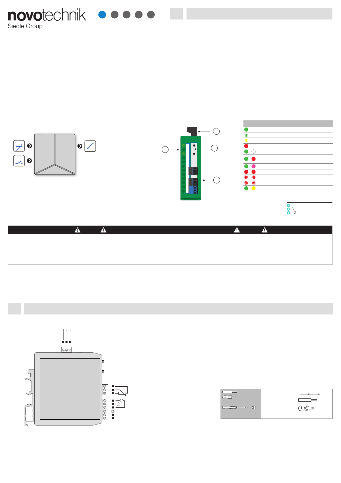
EXTERNAL INPUT
No. of inputs 2
Function EXT 1 KEYLCK Device buttons blocked
(see ch. 3 Device setting)
Function EXT 2 not used
INSTRUMENT SPECIFICATION
TC 15 ppm/°C
Accuracy ±0.01 % of FS
Rate 100…7 200 measurements/s
speed of 400 meas./s is with FFT
signal ltering
Latency < 580 µs
Overload 10x (t < 30 ms), 2x
Functions Teach-in, Tare, Math. functions,
Simulation (only via OMNI Link)
Digital lters exponentia l / oatin g / arithmetic aver-
age, rouding (only via OMNI Link)
Math functions polynomial/ inverse polynomial/loga-
rithm /exponential / power / root (only
via OMNI Link)
Linearization linear interpolation in 100 points
(only via OMNI Link)
OMNI Link On request: company communica-
tion interface for operation, setting and
update of instrument (microUSB).
Watch-dog reset after 500 ms
Calibration at 25°C and 40 % r.h.
ANALOG OUTPUT
No. of outputs 1
Type isolated, adjustable with 16-bit DAC,
output type and range is selectable
TC 15 ppm/°C
Non-linearity 0.024 % of FS
Accuracy ±0.02 % of FS
±0.03 % of FS 0…5 V
±0.05 % of FS 0…2 V / 0…5 mA
Rate response to change of value < 160 µs
Output signals 0…2/5/10 V, ±10 V, resistive load ≥ 1 kΩ
0…5/20 mA/4…20 mA, comp. < 500 Ω/12 V
Indication of error message (output < 3.2 mA)
POWER SUPPLY
Power 10…30 VDC/24 VAC, ±10 %, 2.5 VA,
PF ≥ 0.4,
ISTP< 40 A/1 ms, isolated
Fuse inside (T500 mA)
MECHANIC PROPERTIES
Material PA66, incombustible UL 94 V-0, green
Dimensions 25 x 79 x 90.5 mm (w x h x d)
Installation to DIN rail 35 mm wide
OPERATING CONDITIONS
Connection connector terminal blocks,
section < 1.5 mm2
Stabilization
period
within 5 minutes after switch-on
Working temp. -20°…60°C
Storage temp. -20°…8 5°C
Working
humidity
< 95 % r.h., non condensing
Protection IP20
Construction safety class I
El. safety EN 61010-1, A2
Dielectric
strength
2.5 kVAC for 1 min. between power
supply and signal input
2.5 kVAC for 1 min. between signal
input and outputs
Insulation
resistance*
for pollution degree II, measurement cat. III
power supply > 300 V (PI), 255 V (DI)
Input/outputs > 300 V (PI)
EMC EN 61326-1 (Industrial area)
RoHS EN IEC 63000 : 2018
Seismic
qualication
IEC/IEEE 60980-344 Edition 1.0, 2020, par. 6, 9
Mechanical
resistance
EN 60068-2-6 ed. 2:2008
* PI - Primary insulation, DI - Double insulation
5Technical data
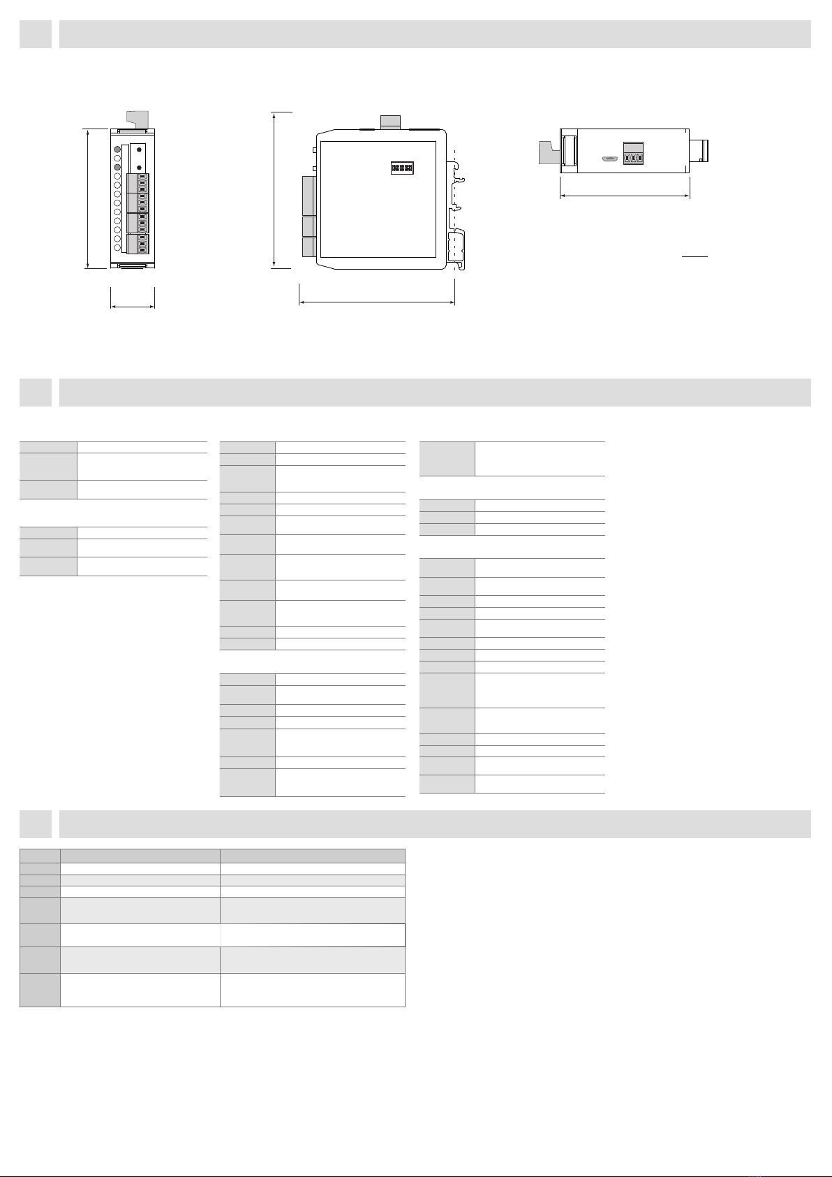
4 Instrument dimensions and installation
Side view
mm
inch
Front view
25
0.98
3.11
Top view
3.54
3.56
79
Lo
Hi
2
90,5
90
1 2 3 4 5 6 7 8
ON
Installation to DIN rail of 35 mm width
2.91
74
6Error Messages
Error Error description Solution
ERR 1 Input range exceeded by ±10% or more. Change input signal value or input setting (range).
ERR 3 Potentiometer wire broken. Check sensor cable and connection.
ERR 10 Output current loop broken. Check cable and current loop connection.
ERR 34 User conguration could not be loaded from
EEPROM.
Default conguration automatically applied.
Repeat device conguration.
If message is shown repeatedly, send the device for repair.
ERR 35 Factory calibration has been lost. Converter’s
accuracy is compromised up to ±5%
When this error occurs, send the device for
re-calibration or upload factory calibration data.
ERR 36 User calibration could not be loaded from
EEPROM. Factory calibration automatically
applied.
Repeat the user calibration.
If message is shown repeatedly, send the device for repair.
ERR 50 Serious device error - damaged EEPROM.
The device operates in an emergency mode, i.e.
settings cannot be changed. Measurement error
can be up to 5%
Send the device for repair.
MINI-TECHDOK - MUP-410_AO - 2023.1.7 - en
4 / 4www.novotechnik.de

Novotechnik Messwertaufnehmer OHG
Horbstrasse 12, 73760 Ostldern,
Germany
+49 711 4489-250 support@novotechnik.de
Measuring instruments of the MUP-410 series conform to the European regulation 2014/30/EU, 2014/35/EU and 2011/65/EU, 2015/863/EU.
This product must be installed, connected and used in compliance with prevailing standards and/or installation regulations.
As standards, specifications and designs develop from time to time, always ask for confirmation of the information given in this publication.
MINI-TECHDOK - MUP-410_AO - 2023.1.7 - en
4 / 4www.novotechnik.de
Other novotechnik Media Converter manuals
Popular Media Converter manuals by other brands

Sima
Sima GoDVD! CT-2 user manual

Gopel Electronic
Gopel Electronic USB 4113 user manual

Crestron
Crestron DM-NVX-D80-IOAV quick start

Siemens
Siemens ZTH Getting started

Panasonic
Panasonic WJ-GXE100 installation guide

Jefferson Professional Tools & Equipment
Jefferson Professional Tools & Equipment JEFKVS04 user guide