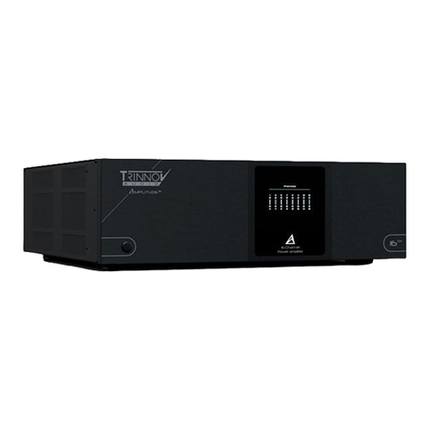
Trinnov Audio AMPLITUDE 8M User manual

AMPLITUDE8M
www.trinnov.com
8-ch Power
Amplier


USER MANUAL
3

4
Amplitude8m
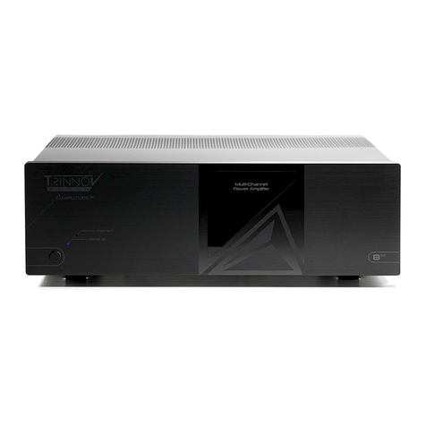
The Amplitude8m amplier is among the most advanced available.
By combining high-power linear power supplies and the Class D,
N-Core® NC-500 OEM amplier modules, Trinnov Audio has delivered
an amplier that closely approaches the theoretical ideal:
a straight wire with gain.
Amplitude8m owner’s manual
June, 2019

3
CONTENT
3
PREFACE
9
9
9
9
10
11
12
5
CONTENT
1
ABOUT THE AMPLITUDE8m
1.1 GETTING TO KNOW YOUR AMPLITUDE8M
1.2 BURN-IN TIME
1.3 IMPORTANT RECOMMENDATION
1.4 SPECIFICATIONS
1.5 THE FRONT PANEL
1.6 THE REAR PANEL
13
13
2
OPERATION
2.1 ENVIRONMENTAL NOTICE
2.2 REMOTE TRIGGERS
15
15
15
APPENDIX
A.1 TROUBLESHOOTING SOLUTIONS
A.2 DB25 TASCAM PINOUT
7
IMPORTANT SAFETY INSTRUCTIONS
4
5
6
8
8
8
9
10
11
12
12
13
13
13

6
Amplitude8m
4
IMPORTANT SAFETY
INSTRUCTIONS
CAUTION:
TO REDUCE THE RISK OF ELECTRICAL
SHOCK, DO NOT REMOVE COVER (OR BACK).
NO USER-SERVICABLE PARTS INSIDE.
REFER SERVICING TO QUALIFIED SERVICE
PERSONNEL.
The lightning flash with
arrowhead symbol, within an
equilateral triangle, is intended
to alert the user to the presence
of uninsulated “dangerous
voltage” within the product’s
enclosure that may be of
significant magnitude to
constitute a risk of electric
shock to persons.
The exclamation point within
an equilateral triangle is
intended to alert the user to
the presence of important
operating and maintenance
(servicing) instructions in the
literature accompanying the
product.
TO REDUCE THE RISK OF FIRE OR ELECTRIC SHOCK, DO NOT EXPOSE THIS PRODUCT
TO RAIN OR MOISTURE.
CAUTION: TO PREVENT ELECTRIC SHOCK, DO NOT USE THE AC (POLARIZED) PLUG
WITH AN EXTENSION CORD, RECEPTACLE OR OTHER OUTLET UNLESS THE BLADES
CAN BE FULLY INSERTED TO PREVENT BLADE EXPOSURE.
EXTENSION CORDS ARE NOT RECOMMENDED FOR USE WITH THIS PRODUCT.
THIS UNIT CONTAINS VOLTAGES WHICH CAN CAUSE SERIOUS INJURY OR DEATH.
DO NOT OPERATE WITH COVERS REMOVED. REFER ALL SERVICING TO YOUR
AUTHORIZED TRINNOV AUDIO DEALER.
FOR CONTINUED PROTECTION AGAINST FIRE HAZARD, REPLACE FUSES ONLY WITH
THE SAME TYPE AND RATING OF FUSES AS SPECIFIED.

USER MANUAL
7
5
CAUTION: TO REDUCE THE RISK OF ELECTRICAL SHOCK, DO
NOT REMOVE ANY OF THE COVER PANELS.
NO USER-SERVICEABLE PARTS INSIDE. REFER ALL SERVICING
TO QUALIFIED SERVICE PERSONNEL ONLY.
TO PREVENT FIRE OR SHOCK HAZARD, DO NOT ALLOW
LIQUIDS TO SPILL OR OBJECTS TO FALL INTO ANY OPENINGS
OF THE PRODUCT.
THIS UNIT IS SUPPLIED WITH ONE 3 PIN GROUNDED AC PLUG.
THE FUSE USED IS 20 AMP IEC C20 INLET. ALWAYS INSERT THE
AC PLUG INTO A GROUNDED OUTLET. DO NOT REMOVE THE
GROUND PIN OR DISABLE THE GROUND FOR ANY PURPOSE.
BEFORE MAKING ANY CONNECTIONS TO THE AMPLITUDE 8m,
FIRST TURN OFF THE POWER AND THEN DISCONNECT THE AC
POWER CORD.
WHEN INSTALLING THE AMPLITUDE8m IN YOUR SYSTEM, MAKE
CERTAIN TO ALLOW A MINIMUM OF ½ INCH OF VENTILATION
ON EACH SIDE OF THE UNIT. ALSO ALLOW AT LEAST 3 INCHES
OF VENTILATION SPACE ABOVE THE UNIT. IMPROPER
VENTILATION OF THE UNIT MAY CAUSE OVERHEATING, WHICH
MAY DAMAGE THE UNIT AND CAUSE A FIRE. PLACE THE UNIT
ON A SOLID SURFACE ONLY. I.E. NOT ON CARPET, ETC.
DO NOT PLACE THE AMPLITUDE8m NEAR HEAT SOURCES SUCH
AS DIRECT SUNLIGHT, STOVES, HEAT REGISTERS, RADIATORS
OR OTHER HEAT PRODUCING EQUIPMENT.
TO PREVENT DAMAGE TO THE ANALOG OUTPUT CIRCUITRY, BE
CERTAIN NOT TO SHORT THE OUTPUT SIGNAL TO GROUND.
ENSURE THAT YOUR AUDIO OUTPUT CABLES DO NOT HAVE
ANY INTERNAL SHORTS BEFORE CONNECTING THEM TO THE
AMPLITUDE8m.
IF REPLACEMENT OF THE AC LINE FUSE AND/OR ANY
INTERNAL FUSE BECOMES NECESSARY, REPLACE ONLY WITH
SAME VALUE AND TYPE OF FUSE. NEVER BYPASS THE FUSE.
IF THE AC CORD BECOMES DAMAGED, DO NOT USE IT.
IMMEDIATELY REPLACE IT WITH A NEW ONE OF THE SAME OR
BETTER RATING.
IT IS IMPERATIVE THAT THE AMPLITUDE8m BE OPERATED IN A
WELL VENTILATED ENVIRONMENT AND THE IMMEDIATE
EXTERNAL TEMPERATURE BE MAINTAINED AS SPECIFIED.
EXTERNAL COOLING FANS MAY BE REQUIRED IN SOME CASES.
DO NOT STACK ANY EQUIPMENT DIRECTLY ABOVE OR BELOW
THE AMPLITUDE 8m AS TO PROTECT IT FROM OVERHEATING,
AS WELL AS THE CONTINUED FUNCTIONALITY OF ANY
EQUIPMENT NEAR AND AROUND IT.
AFTERMARKET and THIRD PARTY MODIFICATIONS
Please note that any aftermarket and/or third party
modifications will void the warranty. In the case of changing the
feet on a unit, in order to prevent any damage (which will also
not be covered under warranty), please verify that the screws
being used to secure non-Trinnov Audio feet do not screw any
deeper into the chassis than the original ones.
PLEASE CAREFULLY READ EACH ITEM OF THE OPERATING INSTRUCTIONS AND SAFETY PRECAUTIONS
BEFORE INSTALLING AND USING THIS PRODUCT. USE EXTRA CARE TO FOLLOW THE WARNINGS
WRITTEN ON THE PRODUCT ITSELF AND/OR IN THE OPERATING INSTRUCTIONS. KEEP THE OPERATING
INSTRUCTIONS AND SAFETY PRECAUTIONS FOR FUTURE REFERENCE.

8
Amplitude8m
6
1.1 GETTING TO KNOW YOUR AMPLITUDE8M
This Amplitude8m has been put through a rigorous and unique testing procedure that ensures that it will last for many
years with minimal service requirements. This procedure includes the following:
• All assembled circuit boards are given a thorough visual inspection and are then tested in a bench reference
Amplitude8m.
• The tested, assembled circuit boards are then installed in a new Amplitude8m and the whole unit is tested for
every function and parameter.
• The unit is put on a burn-in torture rack to test for any possible component failures.
• It is then tested on an audio analyzer for all pertinent parameters.
• The unit has all remaining chassis components installed and then undergoes a complete visual inspection,
which assures that all Amplitude8m’s meet visual specifications.
• The Amplitude8m then undergoes a critical listening and functional test.
1.2 BURN-IN TIME
While the Amplitude8m amplifier will sound wonderful without any burn-in time, users may experience sonic
improvements during the first week or so of operation.
1. ABOUT THE AMPLITUDE8m
1.3 IMPORTANT RECOMMENDATION
Before turning on your Amplitude8m, make sure you are using the right fuse in function of your local current :
• 20 Amp fuse for 120V (The 20 Amp fuse is installed by default).
• 12,5 Amp fuse for 230V.

USER MANUAL
9
7
GAIN
POLARITY
INPUT IMPEDANCE
ANALOG AUDIO OUTPUTS
FREQUENCY RESPONSE
DAMPING FACTOR
SIGNAL TO NOISE RATIO
CROSSTALK
POWER OUTPUT
19 dB
Pin-2 = Positive, Pin-3 = Negative for Non-Inverting Output
47 kOhms for each phase
8 pairs of outputs with 5-way binding posts
+ 0, - 0.5 dB 5 Hz to 20 kHz, load independent
>800 at any frequency up to and including 20 kHz
123 dB referenced to rated output (A-Weighted)
>90 dB
8x8 ohms: 200W RMS per channel with less than 0.05% THD from 20 Hz to 20 kHz
4x4 ohms: 300W RMS per channel with less than 0.05% THD from 20 Hz to 20 kHz
Conventions: For clarity, references to buttons and LED’s will be shown in BOLD, CAPITAL LETTERS.
1.4 SPECIFICATIONS
POWER REQUIREMENTS
POWER CONSUMPTION
TRIGGER INPUT
MODES /PROCESS
Less than 0,5W at Standby (for 230V, 1W for 120V); <80W at idle; 40W at Sleep; 1800W fully
loaded
3U
above 61.6 lbs; 27.7 kG
• Temperature: 0°C – 40°C (32°F – 104°F)
• Humidity: 20% – 80% relative humidity
(without condensation)
127 mm
(feet included)
431.8 mm
482.6 mm
120VAC (90V-132V) / 230VAC (200V-250V) 50/60Hz – 20 Amp fuse for 120V, 12.5 Amp fuse for
230V
Standby: Amplifier is ready to be turned on via front panel switch or remote trigger.
Overcurrent, D.C., and/or thermal protection: Amplifier will cycle.
Catastrophic D.C. or output stage failure: Amplifier will shut down.
5-12 VDC; Steady State

10
Amplitude8m
8
1.5 THE FRONT PANEL
STANDBY BUTTON
1
2
3
Press the front panel STANDBY button to enter or exit the Standby mode.
STANDBY LED
Illuminates RED when the amplifier enters the Standby mode. Illuminates white when the amplifer goes into sleep
state (sleep happens after 10 minutes of no audio input). Illuminates GREEN when the amplifier is in the turn-on
sequence. Illuminates BLUE when the amplifier is ready for normal operation.
PROTECT LED
Illuminates if the unit enters the protection mode. This can be caused by a short circuit in any of the channels or
by an over-temperature operating condition.
1
2
3

USER MANUAL
11
9
1.6 THE REAR PANEL
6
4GROUNDING LUG
Used to interconnect chassis of associated components if
necessary.
18 BALANCED INPUTS ON XLR CONNECTOR
Do not connect XLR and DB25 simultaneously.
28 BALANCED INPUT ON BD25 CONNECTOR
Tascam pinning. Do not connect XLR and DB25 simultaneously.
3REMOTE TRIGGER INPUT / REMOTE TRIGGER OUTPUT
Refer to Chap. 2.2 (Page 12)
5REAR PANEL FUSE
7
Use same type and rating only.
20 Amp for 120V, 12.5 Amp for 230V.
AUTOMATIC AC POWER RECOGNITION
AC Inlet: use the included power cord to connect your amplifier to
an AC power source.
8 BINDING POSTS
Connect the negative to the – (minus) and the positive to the +
(plus) speaker connector. The binding posts can accept spade
plugs, banana plugs or bare wire.

12
Amplitude8m
10
2.1 ENVIRONMENTAL NOTICE
Here are very important instructions to follow before to power on your Amplitude8m:
I. It is imperative that the Amplitude8m be connected to a ground via its three wire AC power cord. It is important
that the AC power outlet, which the Amplitude8m is plugged into, is actually grounded. Failure to do so will
severely compromise the performance, reliability and safety of use of the Amplitude8m.
II. Ventilation is an important issue when placing the Amplitude8m in a system. Make certain that the Amplitude8m
is placed in a well-ventilated area or rack unit.
III. Please take note that some powerline conditioners defeat the AC power ground on their outlets. If the
intention is to plug the Amplitude8m into a line conditioner, check with your dealer to make certain that the
particular conditioner that is intended for use DOES NOT DEFEAT THE AC GROUND on its AC outlets. Only
the highest powered line conditioners should be considered for use with the Amplitude8m. Otherwise, the
amplifier’s power output may be compromised.
IV. DO NOT remove any cover panels from the Amplitude8m, as there are no user serviceable components inside.
Refer servicing and updating to qualified service personnel only.
V. It is imperative that the Amplitude8m be operated in a well ventilated environment and the immediate external
temperature be maintained as specified in Appendix B of this manual. External cooling fans may be required in
some cases. Do not stack any equipment directly above or below the Amplitude 8m, to protect it from
overheating, as well as the continued functionality of any equipment near and around it.
2. OPERATION
Before turning on the Amplitude8m, ensure that all precautions and warnings have been carefully
reviewed and adhered to. Damage to the Amplitude8m caused by improper operation, wiring and/or
ventilation will not be covered under warranty and Trinnov Audio will not be liable for any
consequential damage or loss.
When the amplifer is connected, the amp goes into Standby. The amplifier is completely off, save for a
very small (and low power) supply to power the soft start circuit. When the Standby button is pressed,
the soft start sequence begins and the LED turns green. Several relay clicks may be heard while the
amplifier readies itself for operation. When the turn-on sequence is complete the LED will illuminate
blue and the amp will be fully on. Pressing the Standby button again takes the amp directly into the
standby mode.
2.2 REMOTE TRIGGERS
Use the remote trigger to connect to a compatible preamplifier, source device or other product with 5 to 12 VDC output.
When so interconnected, the Amplitude8m will turn on and off in response to the signals received from the source
device. The trigger circuit requires a steady-state signal. Units that send a pulse signal for turn-on and turn-off will not
work with the Amplitude8m.
The trigger output will pass through the steady-state signal received on the trigger input to switch downstream devices
on and off.

USER MANUAL
13
11
A.1 TROUBLESHOOTING SOLUTIONS
If the Amplitude8m should function abnormally during operation, please review the items in the following checklist.
Please be sure to thoroughly check all other connected components such as speakers, preamplifiers, as well as cables.
A. APPENDIX
SYMPTOM
No power or front panel lights and no sound.
POSSIBLE CAUSE(S)
Power cable is not inserted 100% into AC input
connector.
REMEDY
Ensure that the AC cord is inserted all the way
into the Amplitude8m and that the wall outlet is
active.
Rear panel fuse is open. Replace with same type and rating ONLY.
Circuit breaker is open (AC outlet). Check the AC outlet circuit breaker and reset, if
necessary, or contact your dealer.
No audio output. Overheating. If the front panel PROTECT LED illuminates,
this could indicate overheating. Shut down the
Amplitude8m until in cools. This should be a
very rare occurrence. If it does happen, an
external fan may be required.
A.2 DB25 TASCAM PINOUT
The input DB25 Tascam Pinout is also printed on the back panel of the Amplitude8m. Do not connect XLR and DB25
simultaneously.
H = Hot
C = Cold
G = Ground

Thank you for your attention.
Please enjoy your speaker layout.


TRINNOV AUDIO Headquarters- 5 rue Edmond Michelet - 93360 Neuilly-Plaisance
Phone: +33 (0)1 47 06 61 37
Email: sales@trinnov.com - www.trinnov.com
Other manuals for AMPLITUDE 8M
1
Table of contents
Other Trinnov Audio Amplifier manuals
Popular Amplifier manuals by other brands

Pioneer
Pioneer SA-508 operating instructions

Cooper Instruments & Systems
Cooper Instruments & Systems DFI 2555 SERIAL Communications guide

OT Bioelettronica
OT Bioelettronica NOD user manual
Realistic
Realistic SA-2001 Service manual
Profile
Profile California Mosfet 400SX Installation and owner's manual
QUAD
QUAD 303 Service data
