Trio TS-440S User manual

F
TRIO
HF
TRANSCEIVER
TS-4405
|
INSTRUCTION
MANUAL
TRIO-KENWOOD
CORPORATION
©PRINTED
IN
JAPAN
B50-8049-00(T\(T)
87/654321
861211109876543
$——
`
Thank
you
for
purchasing
the
new
TS-440S/44X
tran-
sceiver.
Please
read
this
instruction
manual
carefully
before
placing
your
transceiver
in
service.
This
unit
has
been
carefully
engineered
and
manufactured
to
rigid
quality
standard,
and
should
give
you
satisfactory
and
dependable
operation
for
many
years.
The
following
explicit
definitions
apply
in
this
manual:
1.
This
Instruction
Manual
covers
the
TS-440S
and
TS-44X,
both
with
and without
AT
(Au-
tomatic
Antenna
Tuner)
unit.
When
there
are
differences
in
operation
separate
instructions
will
be
given
for
each
model.
Illustrations
show
the
TS-440S
with
AT
unit.
2.
Inthe
U.K.
the
TS-440S
is
available
under
the
brand
name
“TRIO”.
The
TS-440S
with
KENWOOD
brand
appearing
in
this
instruction
manual
are
not
sold
in
the
U.K.,
as
they
are
made
to
a
different
market
specification.
CONTENTS
Note:
If
disregarded,
inconvenience
only,
no
risk
of
equipment
damage
or
personal
injury.
Caution:
Equipment
damage
may
occur,
but
not
per-
sonal
injury.
1.
FEATURES...............................................
3
2.
INSTALLATION
........................................
4
2-1.
PRECAUTIONS.....................................
4
2-2.
FIXED
STATION...................................
4
2-2-1.
Interconnection
.......................................
4
2-2-2.
Grounding
..............................................
4
2-2-3.
Antenna.................................................
5
2-2-4.
Key
connection
.......................................
5
2-3.
MOBILE...............................................
5
2-3-1.
Mounting
bracket
installation
....................
5
2-3-2.
Power
supply
connection..........................
5
3.
OPERATION.............................................
6
3-1.
OPERATING
CONTROLS........................
6
3-1-1.
Front
panel.............................................
6
3-1-2.
Rear
panel............................................
10
3-1-3.
Top
cover.............................................
11
3-2.
RECEIVE............................................
12
3-2-1.
Initial
setting.........................................
12
3-2-2.
CW
zero-beat
operation..........................
12
3-2-3.
Direct
keyboard
frequency
entry
..............
13
3-2-4.
AM
reception........................................
13
3-3.
TRANSMIT........................................
13
3-3-1.
SSB
(LSB,
USB)
mode............................
13
3-3-2.
CW
mode.............................................
14
(a)
Semi-automatic
break-in
....................
14
(b)
Full-automatic
break-in
......................
14
3-3-3.
FM
mode
..ssseeserssrerssrasereersserrers
14
e
Subaudible
tone.................................
15
3-3-4.
AM
mode
...eeseeresessssrsserserresrver
15
3-4.
AUTOMATIC
ANTENNA
TUNER
...........
15
3-5.
DUAL
DIGITAL
VF0O's.........................
15
3-5-1.
Why
two
VFO's....................................
15
3-5-2.
Split
frequency......................................
15
(a)
ASB
Switch...
15
(b)
A/B
switch......................................
15
(c)
SPLIT
switch...................................
15
(d)
T-F
SET
switch................................
15
3-6.
MEMORY
..........................................
16
3-6-1.
Memory
entry
.......................................
16
3-6-2.
Transferring
memory
information
to
the
VFO
....................................................
16
3-6-3.
Transferring
data
between
memory
channels
..............................................
17
3-6-4.
Entering/Transferring
data
in
the
split
frequency
channels................................
17
3-6-5.
Clearing
a
memory
channel.....................
17
3-6-6.
Memory
recall.......................................
17
3-7.
SCAN...............................................
18
3-7-1.
Memory
scan........................................
18
3-7-2.
Program
scan........................................
18
3-8.
AFSK................................................
18
3-8-1.
Reception.............................................
18
3-8-2.
Transmit
..............................................
19
3-9.
OPERATION
WITH
A
LINEAR
AMPLIFIER..
19
4.
CIRCUIT
DESCRIPTION
...........................
20
4-1.
GENERAL
DESCRIPTION
....................--
20
4-2.
TRANSMITTER
SECTION
...................--
20
4-3.
RECEIVER
SECTION............................
20
4-4.
CIRCUIT
BOARD
DESCRIPTION
............
20
4-4-1.
RF
unit
(X44-1680-00)...........................
20
4-4-2.
IF
unit
(X60-1300-00)............................
20
4-4-3.
Control
unit
(X53-1450-00)
....................
20
4-4-4,
PLL
unit
(X50-2050-00)
............
emen
20
4-4-5.
Final
unit
(X45-1470-0O0)
........................
20
4-4-6.
Filter
unit
(X51-1340-00)........................
20
4-4-7.
AT
(Automatic
Antenna
Tuner)
unit
(X57-1150-00)......................................
20
5.
MAINTENANCE
AND
ADJUSTMENT
.........
21
5-1.
GENERAL
INFORMATION
....................
21
5-2.
SERVICE
...........................................
21
5-3.
CLEANING.........................................
21
5-4.
IN
CASE
OF
DIFFICULTY.....................
21
5-5.
MICROPROCESSOR
BACK-UP
LITHIUM
BATTERY
.............................
22
5-6.
MICROPROCESSOR
RESET
..................
22
5-7.
ORDERING
SPARE PARTS
...................
22
5-8.
ADJUSTMENTS..................................
23
5-8-1.
Cover
removal.....................................
23
5-8-2.
Internal
views
.....................................
23
5-8-3.
Digital
display
calibration
......................
24
5-8-4.
Optional
10
Hz
display
resolution...........
24
5-8-5.
CW
zero
beat
frequency
selection
..........
24
5-8-6.
Side
tone
level....................................
25
5-8-7.
Beep
tone
selection..............................
25
5-8-8.
Beep
tone
level
...................................
25
5-8-9.
Tuning
dial
torque................................
26
5-8-10.
Linear
amplifier
control
.........................
26
6.
OPTIONAL
ACCESSORIES
.......................
27
6-1.
CRYSTAL
FILTER
INSTALLATION
.........
27
6-2.
VOICE
SYNTHESIZER
UNIT
VS-1
INSTALLATION
..................................
28
6-3.
INTERFACE
IC
KIT
IC-10
INSTALLATION
..................................
29
6-4.
OTHER
ACCESSORIES
........................
30
7.
BLOCK
DIAGRAN....................................
33
8.
SCHEMATIC
DIAGRAM
...................
34
9.
SPECIFICATIONS
AND
ACCESSORIES
......
41
9-1.
SPECIFICATIONS................................
41
9-2.
ACCESSORIES
...................................
42
10.
REFERENCE
...........................................
43
10-1.
ANTENNA
INSTALLATION
.................
43
10-1-1.
Fixed
station.......................................
43
10-1-2.
Mobile...
43
10-2.
MOBILE
OPERATION
...ssessessssesresseesnes
44
10-2-1.
Installation
...........................................
44
10-2-2.
Noise
reduction
...................................
45
10-3.
RADIO
FREQUENCY
ALLOCATION......
46

1.
FEATURES
1.
Wide
dynamic
range
New
advances
in
circuit
design
have
made
a
102
dB
dynamic
range
(500
Hz
IF
bandwidth)
possible.
2.
General
coverage
reception
from
100
kHz
to
30
MHz
In
addition
to
transmission
and
reception
on
all
amateur
bands
from
1.8
to
28
MHz,
the
TS-440S/44X
provides
a
continuous
tuning
general
coverage
receiver
with
a
range
of
100
kHz
to
30
MHz.
3.
Automatic
antenna
tuner
The
optional,
built-in
automatic
antenna
tuner
will
oper-
ate
from
3.5
to
28
MHz.
4.
All-mode
operation
USB,
LSB,
CW,
AM,
FM,
and
AFSK
modes
are
provided.
5.
100%
continuous
duty
transmit
Transmission
at
a
100%
duty
cycle
is
possible
for
rela-
tively
long
durations
(one
hour
or
less)
in
any
mode,
including
FM
and
AFSK.
6.
CW
full
break-in
Full
break-in
operation
is
possible
in
the
CW
mode.
Rapid
transmit/receive
switching
also
makes
the
radio
suitable
for
data
communications
in
the
SSB
mode,
such
as
AMTOR.
7.
Build-in
XIT
XIT
(Transmitter
incremental
tuning)
allows
fine
tun-
ing
of
the
transmitter
frequency.
8.
Switchable
IF
bandwidth
The
IF
bandswitch
allow
you
to
tailor
the
bandwidth
to
the
operating
conditions.
Several
selections
are
provided;
AUTO,
W
(Wide),
M1
(Medium
1),
M2
(Medi-
um
2)
and
N
(Narrow).
When
the
AUTO
position
has
been
selected
the
radio
will
select
the
optimum
band-
width
for
the
selected
mode
of
operation.
9.
Switchable
AGC
time
constant
A
switch
is
provided
to
select
either
FAST
or
SLOW
AGC
action.
10.
All
mode
squelch
11.
Built-in
RF
power/SWR
meter
12.
Versatile
frequency
control
*
Accurate
frequency
selection
is
possible
due
to
the
use
of
a
single
reference
oscillator
circuit.
e
Continuous
tuning
of
all
frequencies
thru
the
use
of
digital
VFO
technology.
The
basic
10
Hz
step
tun-
ing
rate
is
modified,
according
to
the
selected
mode,
for
optimum
tuning
speed
and
accuracy.
An
auto-
matic
fast
scan
function
is
also
provided.
*
Dual,
digital
VFO's
(A/B)
enable
crossband,
cross
mode
operation.
e
100-channel
memory
(including
10
odd-split
chan-
nels)
stores
the
frequency,
band,
and
mode.
e°
Memory
scan
and
two
programmable
scan
ranges.
*
Direct
entry
of
the
desired
frequency
using
the
front
panel
numeric
keypad
is
also
possible.
e
A
memory
scroll
function
allows
review
of
the
memory
channel
contents.
*
Selection
of
the
desired
memory
channel
is
possi-
ble
using
either
the
TUNING
dial
or
microphone
UP/DOWN
pushbuttons.
e°
The
T-F
SET
function
is
useful
for
split
frequency
operation.
*
Anoptional
tone
unit
TU-8
may
be
used
in
conjunc-
tion
with
the
odd-split
memory
channels
to
allow
10
meter
repeater
operations.
*
Optional
computer
interface.
*
Built-in
long-life
memory
back-up
battery.
e
2-color
fluorescent
display
tube
includes
frequency
and
other
operational
data.
13.
Front
panel
control
of
the
TUNING
dial
torque
is
provided.
2.
INSTALLATION
2-1.
PRECAUTION
1.
Avoid
direct
sunlight,
and
select
a
dry,
well
venti-
lated
location.
2.
Since
the
heat
sink
is
on
the
rear
panel,
avoid
plac-
ing
the
equipment
with
the
bottom
and
rear
sides
close
to
a
wall
or
desk.
3.
When
installing
the
equipment
in
an
automobile,
en-
sure
adequate
ventilation.
Install
the
equipment
in
2-2.
FIXED
STATION
2-2-1.
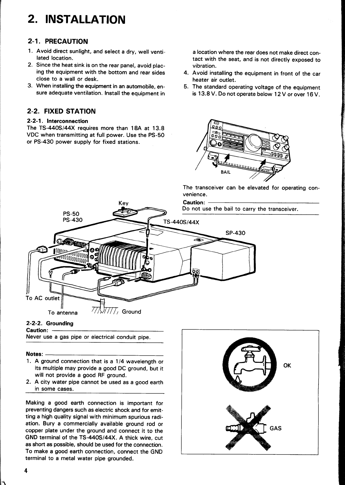
Interconnection
The
TS-440S/44X
requires
more
than
18A
at
13.8
VDC
when
transmitting
at
full
power.
Use
the
PS-50
or
PS-430
power
supply
for
fixed
stations.
,
=
žíl
EH
To
AC
outlet
|
=
To
antenna
2-2-2.
Grounding
Caution:
Never
use
a
gas
pipe
or
electrical
conduit
pipe.
Notes:
1.
A
ground
connection
that
is
a
1/4
wavelength
or
its
multiple
may
provide
a
good
DC
ground,
but
it
will
not
provide
a
good
RF
ground.
2.
A
city
water
pipe
cannot
be
used
as
a
good
earth
in
some
cases.
a
location
where
the
rear
does
not
make
direct
con-
tact
with
the
seat,
and
is
not
directly
exposed
to
vibration.
4.
Avoid
installing
the
equipment
in
front
of
the
car
heater
air
outlet.
5.
The
standard
operating
voltage
of
the
equipment
is
13.8
V.
Do
not
operate
below
12
V
or
over
16
V.
The
transceiver
can
be
elevated
for
operating
con-
venience.
Caution:
Do
not
use
the
bail
to
carry
the
transceiver.
TS-440S/44xX
Making
a
good
earth
connection
is
important
for
preventing
dangers
such
as
electric
shock
and
for
emit-
ting
a
high
quality
signal
with
minimum
spurious
radi-
ation.
Bury
a
commercially
available
ground
rod
or
copper
plate
under
the
ground
and
connect
it
to
the
GND
terminal
of
the
TS-440S/44X.
A
thick
wire,
cut
as
short
as
possible,
should
be
used
for
the
connection.
To
make
a
good
earth
connection,
connect
the
GND
terminal
to
a
metal
water
pipe
grounded.
4
Cat
L
sas

2-2-3.
Antenna
Caution:
Protect
your
equipment—Use
a
LIGHTNING
AR-
RESTOR.
Any
of
the
common
antenna
systems
designed
for
use
on
the
high
frequency
amateur
bands
may
be
used
with
the
TS-440S/44X
provided
the
input
impedance
of
the
transmission
line
is
not
outside
the
capability
of
the
Au-
tomatic
Antenna
Tuner.
The
transmission
line
should
be
coaxial
cable.
An
antenna
system
which
shows
a
SWR
(Standing
Wave
Ratio)
of
less
than
1.5:
1
when
using
50
ohm
coaxial
transmission
line,
or
a
system
that
results
in
a
transmission
line
input
impedance
that
is
essentially
resistive,
and
between
20
and
150
ohms
will
take
power
from
the
transceiver
through
the
AT
unit.
2-2-4.
Key
connection
Your
key
should
be
connected
as
illustrated
in
figure
below.
When
using
an
electronic
keyer,
make
sure
that
polarity
is
set
for
positive.
Always
use
shielded
line
from
the
key
to
transceiver.
Before
connecting,
check
that
the
polarity
is
correct.
The
KEY
jack
provides
+5.5V.
Use
shielded
cable.
KEY
To
key
@—
+5.5V
GND
Key
connection
2-3.
MOBILE
Being
compact
in
design,
this
transceiver
is
ideal
for
mobile
operation.
Satisfactory
mobile
operation
is
achieved
through
proper
power
and
antenna
connec-
tion,
and
thoughtful
transceiver
installation
and
ad-
justment.
2-3-1.
Mounting
bracket
installation
Secure
the
TS-440S/44X
under
the
dashboard
using
an
optional
MB-430
mounting
bracket.
As
an
alterna-
tive,
use
strapping,
making
sure
that
the
TS-440S/44X
will
not
slip
out
of
place
while
operating
the
vehicle.
Notes:
1.
Do
not
install
the
TS-440S/44X
near
the
heater
outlet.
2.
Allow
sufficient
space
behind
the
TS-440S/44X
to
ensure
proper
ventilation.
2-3-2.
Power
supply
connection
Cautions:
1.
Turn
POWER
switch
OFF
before
connecting/dis-
connecting
the
power
cable.
2.
Observe
battery
polarity.
DC
power
cable
Red
and
White
+
Black
and
gray
—
3.
When
charging
your
vehicle
battery,
or
when
jump-
starting
a
dead
battery,
ALWAYS
disconnect
the
power
cable
from
the
back
of
the
transceiver,
or
damage
may
result
to
the
transceiver.
Connect
the
TS-440S/44X
power
cable
to
the
bat-
tery
terminals,
with
consideration
to
current
re-
quirements
and
noise
prevention.
The
maximum
current
drawn
by
the
TS-440S/44X
reaches
to
be-
tween
18
and
20A
when
transmitting.
Therefore,
the
cable
should
be
made
as
short
as
possible,
us-
ing
the
specified
fuse.
Also,
determine
that
the
power
system
of
the
car
(including
the
battery
and
generator
or
alternator)
will
handle
the
increased
load
of
the
TS-440S/44X.
U
se
fuse
essory
p
oO
mum
rati
©
12V
Battery
Use
short
heavy
leads.
terminal
as
possible.
As
sh
Fuse
Fuse
should
be
as
close
to
the
battery

Antenna
your
equipment—Use
a
LIGHTNING
AR-
he
common
antenna
systems
designed
for
use
igh
frequency
amateur
bands
may
be
used
with
140S/44X
provided
the
input
impedance
of
the
ssion
line
is
not
outside
the
capability
of
the
Au-
Antenna
Tuner.
The
transmission
line
should
fal
cable.
An
antenna
system
which
shows
a
anding
Wave
Ratio)
of
less
than
1.5:
1
when
D
ohm
coaxial
transmission
line,
or
a
system
nts
in
a
transmission
line
input
impedance
that
ially
resistive,
and
between
20
and
150
ohms
P
power
from
the
transceiver
through
the
AT
ey
connection
y
should
be
connected
as
illustrated
in
figure
hen
using
an
electronic
keyer,
make
sure
that
is
set
for
positive.
Always
use
shielded
line
P
key
to
transceiver.
Before
connecting,
check
that
the
polarity
is
correct.
The
KEY
jack
provides
+5.5V.
Use
shielded
cable.
+5.5V
To
key
GND
bmpact
in
design,
this
transceiver
is
ideal
for
Operation.
Satisfactory
mobile
operation
is
H
through
proper
power
and
antenna
connec-
H
thoughtful
transceiver
installation
and
ad-
ounting
bracket
installation
he
TS-440S/44X
under
the
dashboard
using
al
MB-430
mounting
bracket.
As
an
alterna-
|
strapping,
making
sure
that
the
TS-440S/44X
slip
out
of
place
while
operating
the
vehicle.
hot
install
the
TS-440S/44X
near
the
heater
t.
W
sufficient
space
behind
the
TS-440S/44X
to
re
proper
ventilation.
2-3-2.
Power
supply
connection
Cautions:
1.
Turn
POWER
switch
OFF
before
connecting/dis-
connecting
the
power
cable.
2.
Observe
battery
polarity.
DC
power
cable
Red
and
White
+
Black
and
gray
—
3.
When
charging
your
vehicle
battery,
or
when
jump-
starting
a
dead
battery,
ALWAYS
disconnect
the
power
cable
from
the
back
of
the
transceiver,
or
damage
may
result
to
the
transceiver.
Connect
the
TS-440S/44X
power
cable
to
the
bat-
tery
terminals,
with
consideration
to
current
re-
quirements
and
noise
prevention.
The
maximum
current
drawn
by
the
TS-440S/44X
reaches
to
be-
tween
18
and
20A
when
transmitting.
Therefore,
the
cable
should
be
made
as
short
as
possible,
us-
ing
the
specified
fuse.
Also,
determine
that
the
power
system
of
the
car
(including
the
battery
and
generator
or
alternator)
will
handle
the
increased
load
of
the
TS-440S/44X.
Use
fuse
block
battery
acc-
s
12V
Battery
Use
short
heavy
leads.
terminal
as
possible.
Fuse
should
be
as
close
to
the
battery
essory
position.
20A
mini-
mum
rating.
As
short
as
possible.
TS-440S/44
Z

3.
OPERATION
3-1.
OPERATING
CONTROLS
3-1-1.
Front
panel
(=
i
SS
mon
1
3
5
79
20]
40
60
M.
CH
SCAN
A
VFO
B
SPLIT
E
L1
L
Lila
nma
D
MDG
Mm
D
G
E
|
voce
ne
ATT
a
19
"RII
W
Got
CO"
-
d
HF
TI
|
H
RANSCEIVER,
co
c
c
t
ALC
PWR
SWR
I
p
Jü
A
EN
J
]
Ñ
Q9
|
s
|
fuse
)
ow
|
Paw]
E]
Le
SEND
AUTO
AT
TUNE
CZ
$1
ILJI
[v-v
Jf
Scan
[CLEAR
[vom
][M.
iN
J[ENT
1
(D
POWER
switch
(8)
Frequency
display
Note:-
Press
to
turn
the
power
ON
or
OFF.
The
operating
frequency
is
displayed
down
to
the
The
sq
nearest
100
Hz.
Also
displays
the
memory
channel
mo
de.
O
Meter
number,
RIT/XIT
frequency,
and
includes
indicators
for
modes
During
receive
the
meter
is
used
as
an
S-meter.
Dur-
Memory,
VFO
A/B,
scan,
split
and
RIT/XIT
operations.
N
ing
transmit
the
function
of
the
meter
is
controlled
by
.
i
Meter
switch,
and
provides
either
ALC
level,
PwR
(6)
FUNCTION
switches
The
(power)
or
SWR
readings.
The
switches
included
in
this
group
are
the
RIT/XIT,
be
^
T-F
SET
switch,
and
the
VFO
select
switches.
(See
e
h
(8)
MODE/KEY
(Numeric
Keypad)
page
15.)
I
rotan
These
keys
are
used
to
select
the
desired
mode
of
oper-
,
Norma
ation
(USB,
LSB,
CW,
AM,
FM,
AFSK).
When
program-
@
MIC
gain
control
and
1:
ming
a
memory
channel
or
directly
entering
a
frequency
Microphone
gain
can
be
adjusted
during
USB,
LSB,
Notes:
these
keys
are
used
as
a
numeric
keypad
to
enter
the
AFSK
and
AM
operations.
Gain
is
increased
thru
clock-
1
9
Th.
channel
number
or
frequency.
wise
rotation
of
this
control.
:
of
(4)
Indicators
CAR
(Carrier
level)
control
2.
a
AT
TUNE:
Lights
when
the
AT
TUNE
switch
is
ON.
This
control
sets
the
carrier
level
during
CW,
FM
and
rot:
Turns
itself
OFF
when
the
antenna
tuner
AM
operations.
When
transmitting
in
the
CW
mode,
the
has
completed
tuning.
adjust
so
that
the
ALC
meter
pointer
is
within
the
ALC
resi
NOTCH:
Lights
when
the
NOTCH
switch
is
ON.
zone.
F.LOCK:
Lights
when
the
F.LOCK
switch
is
ON.
1
MHz:
Lights
when
the
1
MHz
step
switch
is
ON,
9)
SQL
(Squelch)
control
i
M.SCR:
Lights
when
the
M.IN
switch
is
pressed.
This
function
operates
in
all
modes,
FM,
USB,
LSB,
sig
When
the
memory
scroll
function
is
active
CW,
AFSK,
and
AM.
you
can
review
the
contents
of
the
This
control
is
used
to
eliminate
atmospheric
noise,
and
memory
channels
without
a
break
in
the
receiver
static
noise
during
no
signal
periods.
Slowly
reception
of
the
station
you
are
listening
—
rotate
the
control
clockwise
to
the
point
where
the
am-
to.
bient
noise
just
disapears,
and
speaker
shuts
off.
This
—
ON
AIR:
Lights
during
transmit.
point
is
known
as
the
squelch
threshold
point.
Now
you
will
only
hear
output
from
the
speaker
when
an
incom-
ming
signal
is
present.
For
weak
signal
reception
this
control
should
be
fully
counterclockwise.

®
®
@
me
^
so
Norcu]
8
wx
SHIFT
F.LOCK
PROC
NOTCH
AGS
e
T
E
EON
eano
TTT
LL
m)
SELECTIVITY
M1
the
inel
;
for
ns.
KIT,
See
SB,
)ck-
and
de,
LC
SB,
and
wly
am-
his
you
m-
this
ao
—
(9
d$
d)
do
G
Note:
The
squelch
threshold
position
will
vary
from
mode
to
mode,
so
you
may
have
to
readjust
when
you
change
modes.
NOTCH
control
The
NOTCH
function
is
used
to
reduce
or
eliminate
het-
erodyne,
or
CW
type
signals.
The
NOTCH
filter
will
not
be
effective
against
SSB,
AM
or
FM
type
signals.
To
use
the
control,
place
the
NOTCH
switch
ON
and
slow-
ly
rotate
the
NOTCH
control
to
reduce
the
interference.
Normally
the
notch
point
will
occur
between
the
11:00
and
1:00
o'clock
position.
Notes:
1.
The
NOTCH
frequency
can
be
varied
within
a
range
of
approximately
400
to
2600
Hz.
2.
When
an
interfering
signal
such
as
a
CW
station
appears,
slowly
rotate
the
NOTCH
control.
If
you
rotate
the
knob
too
quickly
you
may
pass
right
over
the
notch
point.
Slow
rotation
will
yield
the
best
results.
Interfering
signal
attenuated
by
NOTCH
control
N
|
Receive
Receive
.
signal
signal
Interfering
signal
Audio
output
Audio
output
(NOTCH
OFF)
(NOTCH
ON)
NOTCH
control
eo
oO
ñD
IF
SHIFT
control
Note:
The
IF
SHIFT
control
does
not
function
in
the
AM
or
FM
modes.
The
IF
SHIFT
control
allows
you
to
shift
the
IF
pass-
band
of
the
receiver
without
changing
the
actual
center
frequency
of
the
receiver.
This
control
is
useful
when
there
is
interference
near
your
center
frequency.
As
the
accompanying
illustration
shows
rotating
this
control
may
place
the
interfering
signal
outside
the
receiver
passband,
allowing
for
easier
copy.
The
operation
of
this
control
in
the
USB,
LSB,
AFSK,
and
CW
modes
is
detailed
below.
*
USB
mode
Interference
from
lower
frequencies
can
be
reduced
or
eliminated
by
rotating
the
IF
SHIFT
control
in
the
@
direction.
This
will
cause
the
resulting
audio
fre-
quencies
to
have
a
slightly
treble
response,
i.e.low
cut
filter
(low
frequencies
attenuated).
Interference
from
higher
frequencies
can
be
reduced
or
eliminat-
ed
by
rotating
the
IF
SHIFT
control
in
the
©
direc-
tion.
This
will
cause
the
resulting
audio
frequencies
to
sound
a
little
bassy,
i.e.high
cut
filter
(high
fre-
quencies
attenuated).
*
LSB/AFSK
mode
Interference
from
lower
frequencies
can
be
reduced
or
eliminated
by
rotating
the
IF
SHIFT
control
in
the
@
direction.
This
will
cause
the
resulting
audio
fre-
quencies
to
sound
a
little
bassy,
just
the
opposite
of
the
effect
in
the
USB
mode.
Interference
from
higher
frequencies
can
be
reduced
or
eliminated
by

rotating
the
IF
SHIFT
control
in
the
©
direction.
This
will
cause
the
resulting
audio
frequencies
to
ap-
pear
a
little
on
the
high
side,
again
just
the
opposite
of
the
USB
mode.
°
CW
mode
The
operation
of
the
IF
SHIFT
control
is
similar
to
that
for
USB
with
the
exception
that
you
can
con-
trol
the
tone
of
the
CW
note
by
using
the
RIT
control.
Turned
in
CJdirection
Turned
in
@)direction
IF
filter
passband
=
characteristic
=
® ®
Signal
Signal
Signal
Ointerfering
signal
0
Interfering
signal
RIT/XIT-€)—IF
SHIFT
RIT/XIT—$)—IF
SHIFT
RIT/XIT--1F
SHIFT
KSC
Turn
in
CS
direction
Turn
in
@direction
to
eliminate
inter-
to
eliminate
inter-
ference
from
signal
ference
from
signal
9.
®.
IF
SHIFT
operation
(2
RIT/XIT
control
*
RIT
control
When
the
transmit
frequency
of
the
distant
station
drifts
a
little
bit
during
the
QSO,
but
you
do
not
wish
to
alter
your
transmit
frequency
to
compensate,
you
may
wish
to
make
use
of
the
RIT
control
function.
This
control
allows
shifting
the
receive
frequency
without
shifting
the
transmit
frequency.
The
RIT
control
allows
you
to
shift
the
receiver
frequency
+/—
1.2
kHz.
This
control
is
also
useful
for
pileups
when
the
DX
station
is
transmitting
a
little
above
or
below
his
receive
frequency.
Notes:
1.
The
RIT
offset
is
displayed
on
the
main
display.
You
can
therefore
preset
the
offset
before
you
actually
need
to
use
it.
When
you
move
to
another
station
make
sure
you
turn
OFF
the
RIT
switch.
2.
The
figure
at
the
right
illustrates
that
the
RIT
dis-
play
and
the
VFO
display
may
not
agree
exactly
in
all
instances
since
the
RIT
and
VFO
tune
in
10
Hz
steps.
The
normal
resolution
of
the
VFO
is
100
Hz,
so
if
the
RIT
or
VFO
is
turned
slowly
the
associat-
ed
display
may
not
update
immediately.
You
will
have
to
tune
100
Hz
to
see
the
display
actually
change.
1399999
ao]:
d
d
1399991
-2.0]»
133348]
"EL
ZOO:
Lo
i:
d $
e
XIT
control
When
the
RIT/XIT
control
is
rotated
with
the
XIT
switch
depressed
the
transmit
frequency
can
be
varied
+
/—
1.2
kHz
without
affecting
the
receiver
frequency.
Pressing
the
switch
again
releases
the
XIT
function.
(3
RF
gain
control
This
control
adjusts
the
gain
of
the
receiver
high-
frequency
amplifier
section.
For
normal
receiver
performance,
add
maximum
gain,
this
control
should
be
in
the
full
clockwise
position.
If
you
are
having
trouble
copying
the
desired
signal
make
a
note
of
the
stations
peak
S-meter
reading.
Then,
ad-
just
the
RF
control
counterclockwise,
so
that
the
meter
needle
is
stationary
at
this
level.
Now,
all
signals
that
were
less
than
the
desired
signal
will
be
attenuated,
such
as
static
noise,
etc.,
making
the
completion
of
the
QSO
easier.
If
the
incoming
signal
pegs
the
S-meter
you
can
also
reduce
the
receiver
gain
by
counterclockwise
rotation
of
the
RF
control.
The
S-meter
pointer
will
always
ad-
vance
up-scale
as
the
RF
control
is
rotated
counter-
clockwise,
as
a
visual
reminder
that
the
gain
of
the
radio
has
been
reduced.
AF
gain
control
Turn
the
inside
knob
to
increase
or
decrease
the
volume.
(59
SELECTIVITY
switch
When
an
optional
filter
is
installed,
the
radios
passband
can
be
switched
to
one
of
four
different
bandwidths.
The
switch
has
five
positions;
AUTO,
N,
M1,
M2
and
W,
that
are
used
to
select
the
bandwidth.
The
M1,
and
N
positions
are
not
active
until
the
optional
filters
are
installed,
see
the
accompanying
chart.
This
switch
should
normally
be
set
to
the
AUTO
position.
The
IF
bandwidth
will
then
be
selected
for
optimum
receiver
characteristics,
according
to
the
MODE
that
has
been
selected.
Manual
override
is
possible
by
simple
rota-
tion
of
the
SELECTIVITY
control.
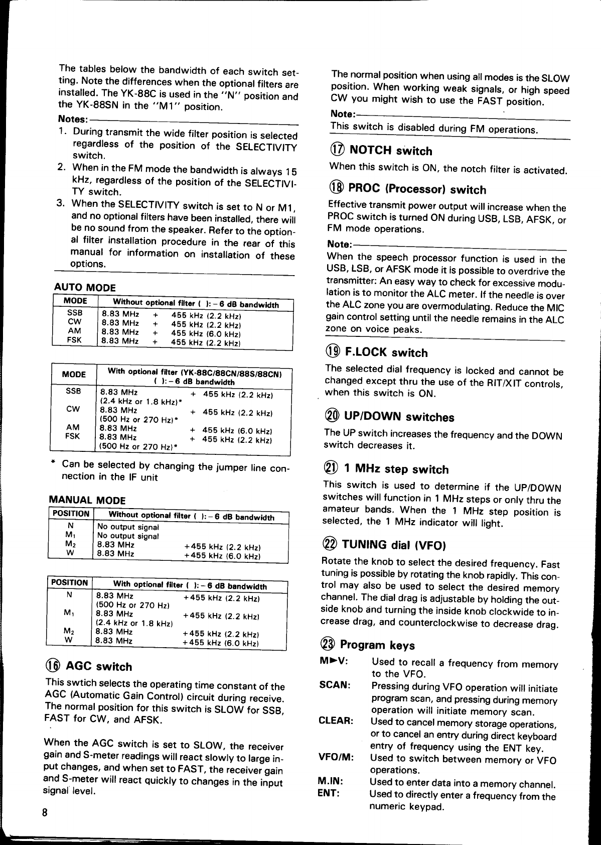
The
tables
below
the
bandwidth
of
each
switch
set-
ting.
Note
the
differences
when
the
optional
filters
are
installed.
The
YK-88C
is
used
in
the
“N”
position
and
the
YK-88SN
in
the
“M1”
position.
Notes:
1.
During
transmit
the
wide
filter
position
is
selected
regardless
of
the
position
of
the
SELECTIVITY
Switch.
2.
When
in
the
FM
mode
the
bandwidth
is
always
15
kHz,
regardless
of
the
position
of
the
SELECTIVI-
TY
switch.
3.
When
the
SELECTIVITY
switch
is
set
to
N
or
M1,
and
no
optional
filters
have
been
installed,
there
will
be
no
sound
from
the
speaker.
Refer
to
the
option-
al
filter
installation
procedure
in
the
rear
of
this
manual
for
information
on
installation
of
these
options.
AUTO
MODE
MODE
Without
optional
filter
(
):
—
6
dB
bandwidth
SSB
8.83
MHz
+
455
kHz
(2.2
kHz)
CW
8.83
MHz
+
485
kHz
(2.2
kHz)
AM
8.83
MHz
+
455
kHz
(6.0
kHz)
FSK
8.83
MHz
+
455
kHz
(2.2
kHz)
MODE
With
optional
fitter
(YK-88C/88CN/88S/88CN)
(
):
—
6
dB
bandwidth
+
455
kH2
(2.2
kHz)
SSB
8.83
MHz
(2.4
kHz
or
1.8
kHz)*
Cw
8.83
MHz
(500
Hz
or
270
Hz)*
AM
8.83
MHz
FSK
8.83
MHz
(500
Hz
or
270
Hz)*
*
455
kHz
(2.2
kHz)
+
455
kHz
(6.0
kHz)
+
455
kHz
(2.2
kHz)
*
Can
be
selected
by
changing
the
jumper
line
con-
nection
in
the
IF
unit
MANUAL
MODE
POSITION
Without
optional
filter
(
):
-
6
dB
bandwidth
N
No
output
signal
M;
No
output
signal
M2
8.83
MHz
w
8.83
MHz
+455
kHz
(2.2
kHz)
+455
kHz
(6.0
kHz)
POSITION
With
optional
filter
(
):
-
6
dB
bandwidth
N
8.83
MHz
+455
kHz
(2.2
kHz)
(500
Hz
or
270
Hz)
M;
8.83
MHz
+455
kHz
(2.2
kHz)
(2.4
kHz
or
1.8
kHz)
M2
8.83
MHz
w
8.83
MHz
+455
kHz
(2.2
kHz)
+455
kHz
(6.0
kHz)
(8
AGC
switch
This
swtich
selects
the
operating
time
constant
of
the
AGC
(Automatic
Gain
Control)
circuit
during
receive.
The
normal
position
for
this
switch
is
SLOW
for
SSB,
FAST
for
CW,
and
AFSK.
When
the
AGC
switch
is
set
to
SLOW,
the
receiver
gain
and
S-meter
readings
will
react
slowly
to
large
in-
put
changes,
and
when
set
to
FAST,
the
receiver
gain
and
S-meter
will
react
quickly
to
changes
in
the
input
signal
level.
8
The
normal
position
when
using
all
modes
is
the
SLOW
position.
When
working
weak
signals,
or
high
speed
CW
you
might
wish
to
use
the
FAST
position.
Note:
This
switch
is
disabled
during
FM
operations.
(2
NOTCH
switch
When
this
switch
is
ON,
the
notch
filter
is
activated.
(8
PROC
(Processor)
switch
Effective
transmit
power
output
will
increase
when
the
PROC
switch
is
turned
ON
during
USB,
LSB,
AFSK,
or
FM
mode
operations.
Note:
When
the
speech
processor
function
is
used
in
the
USB,
LSB,
or
AFSK
mode
it
is
possible
to
overdrive
the
transmitter:
An
easy
way
to
check
for
excessive
modu-
lation
is
to
monitor
the
ALC
meter.
If
the
needle
is
over
the
ALC
zone
you
are
overmodulating.
Reduce
the
MIC
gain
control
setting
until
the
needle
remains
in
the
ALC
Zone
on
voice
peaks.
F.LOCK
switch
The
selected
dial
frequency
is
locked
and
cannot
be
changed
except
thru
the
use
of
the
RIT/XIT
controls,
_
when
this
switch
is
ON.
@0)
UP/DOWN
switches
The
UP
switch
increases
the
frequency
and
the
DOWN
switch
decreases
it.
GI
1
MHz
step
switch
This
switch
is
used
to
determine
if
the
UP/DOWN
switches
will
function
in
1
MHz
steps
or
only
thru
the
amateur
bands.
When
the
1
MHz
step
position
is
selected,
the
1
MHz
indicator
will
light.
@2
TUNING
dial
(VFO)
Rotate
the
knob
to
select
the
desired
frequency.
Fast
tuning
is
possible
by
rotating
the
knob
rapidly.
This
con-
trol
may
also
be
used
to
select
the
desired
memory
channel.
The
dial
drag
is
adjustable
by
holding
the
out-
side
knob
and
turning
the
inside
knob
clockwide
to
in-
crease
drag,
and
counterclockwise
to
decrease
drag.
Q3
Program
keys
M»
V:
Used
to
recall
a
frequency
from
memory
to
the
VFO.
SCAN:
Pressing
during
VFO
operation
will
initiate
program
scan,
and
pressing
during
memory
operation
will
initiate
memory
scan.
CLEAR:
Used
to
cancel
memory
Storage
operations,
or
to
cancel
an
entry
during
direct
keyboard
entry
of
frequency
using
the
ENT
key.
VFO/M:
Used
to
switch
between
memory
or
VFO
operations.
M.IN:
Used
to
enter
data
into
a
memory
channel.
ENT:
Used
to
directly
enter
a
frequency
from
the
numeric
keypad.
C——
GM

@
PHONES
jack
Output
terminal
for
headphones.
Q9
MIC
jack
Connector
for
a
microphone.
GND
(STBY)®
MIC
oO
@GND
(MIC)
STBY
o
©NC
DOWN®
®
8V/approx.
10
mA
UP®
MIC
connector
(Front
view)
Q8
AT
TUNE
switch
When
this
switch
is
turned
ON
with
the
AUTO/THRU
Switch
is
placed
in
the
AUTO
position,
the
automatic
tuner
will
be
engaged
and
the
tuner
will
try
to
match
the
antenna.
:
Q?)
AUTO/THRU
switch
AUTO:
The
auto
antenna
tuner
is
used
in
transmit.
THRU:
The
auto
antenna
tuner
is
not
used
in
transmit.
Q8
Standby
switch
This
switch
is
used
when
you
want
to
manually
con-
trol
transmit
or
receive.
SEND:
Places
the
radio
into
transmit.
REC:
Places
the
radio
into
receive.
The
Standby
switch
is
also
used
to
clear
an
entry
dur-
ing
direct
entry
of
VFO
frequencies,
or
when
entering
a
memory
channel.
(9
ALC/PWR/SWR
meter
switch
ALC
meter
Used
to
monitor
the
drive
level
in
USB,
LSB,
and
AFSK
modes.
PWR
meter
Used
to
indicate
the
output
power.
Note
that
this
meter
is
a
peak
reading
meter,
not
an
average
reading
meter.
SWR
meter
Used
to
indicate
the
Standing
Wave
Ratio
of
the
an-
tenna
and
feedline
connected
to
the
ANT
connector
when
the
AUTO/THRU
switch
is
in
the
THRU
position.
Gi
ATT
(Attenuator)
switch
The
incoming
receive
signal
level
is
attenuated
by
ap-
proximately
20
dB
when
this
switch
is
activated.
When
the
incoming
receive
signal
is
very
strong
(20
dB
over
S-9),
the
signal
should
be
attenuated
to
pre-
vent
distortion
of
the
signal,
thereby
stabilizing
the
receiver
performance.
This
is
easily
done
thru
the
use
of
the
ATT
switch,
simply
turn
it
ON.
This
control
is
also
useful
when
a
strong
signal
is
near
your
desired
signal,
while
some
loss
will
occur
to
the
desired
signal
as
well
as
the
undesired
signal
the
use
of
the
attenua-
tor
will
sometimes
allow
you
to
complete
the
OSO.
61)
NB
(Noise
Blanker)
switch
When
pulsating
noise,
such
as
that
caused
by
automo-
bile
ignitions
is
encountered,
place
the
NB
switch
ON.
This
will
provide
approximately
4O
dB's
of
attenuation
to
this
interfering
signal.
If
there
is
no
noise
present,
the
switch
should
be
in
the
OFF
position.
This
switch
will
not
help
to
eliminate
atmospheric
or
line
noises,
only
pulse
type
noise.
(2
VOICE
switch
When
the
optional
VS-1
voice
synthesize
unit
is
in-
stalled
the
operating
frequency!
will
announced
whenever
the
VOICE
switch
is
depressed.
Far
a
dial
frequency
of
14.200.0
the
frequency
will
be
an-
“”
oi
yeas
nm on
nounced
as:
“one”,
“four”,
“point”,
“two”,
“zero”,
“zero”,
"zero'',
“zero”.
Please
refer
to
page
28
for
installation
instructions
con-
cerning
the
VS-1
Voice
Synthesizer.
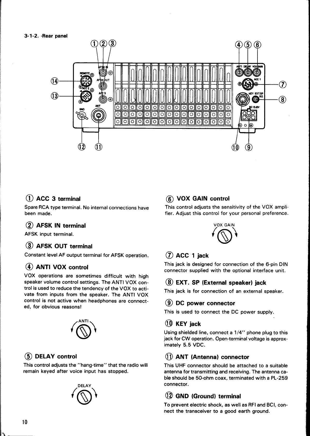
3-1-2.
-Rear
panel
@
ACC
3
terminal
Spare
RCA
type
terminal.
No
internal
connections
have
been
made.
(2)
AFSK
IN
terminal
AFSK
input
terminal.
(8)
AFSK
OUT
terminal
Constant
level
AF
output
terminal
for
AFSK
operation.
(@
ANTI
VOX
control
VOX
operations
are
sometimes
difficult
with
high
speaker
volume
control
settings.
The
ANTI
VOX
con-
trol
is
used
to
reduce
the
tendency
of
the
VOX
to
acti-
vate
from
inputs
from
the
speaker.
The
ANTI
VOX
control
is
not
active
when
headphones
are
connect-
ed,
for
obvious
reasons!
O)
(5)
DELAY
control
This
control
adjusts
the
‘‘hang-time’”’
that
the
radio
will
remain
keyed
after
voice
input
has
stopped.
‘©
10
6)
VOX
GAIN
control
This
control
adjusts
the
sensitivity
of
the
VOX
ampli-
fier.
Adjust
this
control
for
your
personal
preference.
VOX
GAIN
í
D
(7)
ACC
1
jack
This
jack
is
designed
for
connection
of
the
6-pin
DIN
connector
supplied
with
the
optional
interface
unit.
EXT.
SP
(External
speaker)
jack
This
jack
is
for
connection
of
an
external
speaker.
CR
DC
power
connector
This
is
used
to
connect
the
DC
power
supply.
(0
KEY
jack
Using
shielded
line,
connect
a
1/4''
phone
plug
to
this
jack
for
CW
operation.
Open-terminal
voltage
is
approx-
imately
5.5
VDC.
a
ANT
(Antenna)
connector
This
UHF
connector
should
be
attached
to
a
suitable
antenna
for
transmitting
and
receiving.
The
antenna
ca-
ble
should
be
50-ohm
coax,
terminated
with
a
PL-259
connector.
EI
GND
(Ground)
terminal
To
prevent
electric
shock,
as
well
as
RFI
and
BCI,
con-
nect
the
transceiver
to
a
good
earth
ground.

13
ACC
2
jack
Internal
wiring
. .
:
:
View
fro
d
Terminal
numbers
and
their
applications
are
as
follows:
rom
cor
View
from
the
rear
panel.
3-1-3.
Top
cover
RE)
umm
EMEN
13-pin
DIN
plug
VOX
OFF
ON
Pin
No.|
Pin
Name
Application
1
NC
No
connection
2
|NC
No
connection
.
3
|
Data
output
|
Output
level
is
fixed
regardless
of
the
VOX/BREAK
IN
switch
AF
control
setting.
VOX
(Voice
Operated
Switch)
operation
is
possible
in
oo
vonage:
f
LSB,
USB,
FM
or
AFSK
mode
operations.
To
activate
mV
or
more
at
maximum
re-
"M
:
ceiving
input
with
4.7
kQ
load.
the
VOX
circuitry
place
the
VOX
switch
ON.
4
|GND
Grounding
(The
shielded
wire
of
the
N N N .
audio
output
terminal
is
connected
This
control
is
also
used
to
select
either
Full
or
Semi
here.)
automatic
break-in.
5
|NC
No
connection
6
|NC
No
connection
7
|NC
No
connection
8
|GND
Grounding
9
|MIC
mute
Signal
input
from
the
MIC
jack
is
mut-
ed.
Grounding
mutes
signal.
10
|NC
No
connection
11
Data
input
Input
terminal
for
data
communica-
tion.
In
SSB,
MIC
gain
can
be
con-
trolled
by
the
MIC
control.
Input
voltage:
500
mV
or
less
(SSB:
Voltage
starts
deflecting
ALC.
FM:
Voltage
providing
+
3.0
kHz
modulation
ratio.)
12
|GND
Grounding
(The
shielded
wire
of
the
audio
input
is
connected
here.)
13
|Standby
Standby
terminal
Grounding
transmits.
(4
REMOTE
connector
Note:
4
When
the
control
relay
is
used
refer
to
section
5-8-10.
+12
VDC
ON
transmit
GND
max.
10
mA.
-ALC
input
From
standby
switch
(PTT
circuit
for
foot
switch)
‘

3-2.
RECEIVE
POWER
switch:
OFF.
SQL
control:
Fully
counterclockwise.
NN
‘Se
CH
SCAN
^
VO
»
Anas
EE
Or
4
2 8
2
ma
[m
sch
TF
LocK
NOTCH
AT
TUNE]
HF
TRANSCEIVER,
^
RF
gain
control:
Fully
clockwise.
RIT/
XIT
—
F
SHIFT
ar
ES
AF
gain
control:
Fully
counter-
clockwise.
Standby
switch:
Fr]
sr)
;
REC
NS
Z^
9
10
Mev
(Sca
yecens
—
F
Lock
PROC
NOTCH
AGS
—
stecnivirY
AUTO
(coe
oa
ai
"s
—
J
RIT
switch:
OFF
MODE
keys
TUNING
dial
(VFO)
3-2-1.
initial
setting
1.
Preset
the
controls
as
shown
in
the
accompanying
illustration
above.
2.
Place
the
POWER
switch
to
ON.
(During
fixed-
station
operation
you
must
first
turn
ON
your
DC
power
supply,
the
PS-50
is
recommended.)
3.
The
meter
will
illuminate
and
a
frequency
will
ap-
pear
in
the
display.
4.
Set
the
BAND
switches
for
the
desired
band.
If
you
desire
to
tune
a
frequency
other
than
one
of
the
amateur
radio
frequencies,
place
the
1
MHz
switch
ON.
With
the
1
MHz
switch
ON
the
UP/DOWN
switches
will
advance
the
frequency
in
1
MHz
steps,
rather
than
thru
the
amateur
radio
bands.
5.
Select
the
desired
MODE
using
one
of
the
mode
switches.
Notes:
1.
By
international
convention
amateur
radio
fre-
quencies
below
10
MHz
utilize
the
LSB
(Lower
Sideband)
mode,
and
frequencies
of
10
MHz
-and
above
use
USB
(Upper
Sideband).
2.
The
TS-440S/44X
automatically
selects
the
normal
mode
for
you.
The
exact
changeover
point
is
9.5
MHz.
You
can
override
this
selec-
tion
by
pressing
the
desired
mode
switch.
6.
Adjust
the
AF
gain
control
for
the
desired
volume.
7.
Slowly
rotate
the
TUNING
dial
until
the
desired
sig-
nal
can
be
heard
clearly.
8.
The
desired
receive
frequency
can
also
be
entered
directly
by
using
the
numeric
keypad.
For
details
of
this
operation
please
refer
to
the
“Direct
key-
board
frequency
entry”
section
on
page
13.
3-2-2.
CW
zero-beat
operation
Zero-beat
operation
with
a
station
during
CW
mode
operation
1.
Set
the
RIT/XIT
switches
to
OFF.
2.
When
an
optional
filter
is
not
used,
tune
the
TUN-
ING
dial
so
that
the
receive
beat
frequency
is
ap-
proximately
800
Hz.
You
can
check
this
by
turning
the
VOX
OFF,
and
then
closing
your
CW
key.
Then
by
using
the
sidetone
oscillator,
and
the
incoming
receive
signal
you
can
zero-beat
by
turning
the
TUNING
dial
until
the
two
tones
are
the
same
fre-
quency.
3.
When
the
YK-88C
filter
is
used
the
simplest
method
to
use
is
to
adjust
the
TUNING
dial
for
a
maximum
S-meter
deflection.
Reception
at
the
desired
pitch
after
zero-beat
operation.
1.
After
zero-beating
turn
the
RIT
switch
ON,
and
ad-
just
the
RIT
control
for
the
desired
pitch.
2.
Adjust
the
IF
SHIFT
control
for
the
strongest
sig-
nal
level.
Your
frequency
Displayed
frequency
Transmit-Receive
frequency
(Displayed
frequency)
|
Receiver
carrier
frequency
l
{BFO}
N
|
!
800Hz
Beat
note
Tuning
for
CW
Operation

3-2-3.
Direct
keyboard
frequency
entry
Direct
keyboard
entry
of
the
frequency
is
possible
us-
ing
the
numeric
keypad
on
the
TS-440S/44X.
This
al-
lows
rapid
changes
in
frequency
without
the
delays
encountered
when
using
other
tuning
methods.
1.
Select
the
VFO
mode.
2.
Press
the
ENT
key.
The
display
will
indicate
“
"n
A
VFO
3.
Enter
the
desired
operating
frequency
from
Most
Significant
Digit
to
the
Least
Significant
Digit.
You
do
not
have
to
enter
trailing
zeros,
but
you
must
enter
a
leading
zero
for
the
frequency
between
1
and
3.99999
MHz
or
two
leading
zeros
for
the
fre-
quency
between
O.1
and
0.99999
MHz.
(03.500.00
MHz).
4.
After
the
last
digit
has
been
entered
press
the
ENT
key
again
to
signify
you
want
the
radio
to
change
frequency.
If
you
entered
the
frequency
down
to
the
nearest
10
Hz
a
beep
will
sound
and
the
radio
will
automatically
change
to
the
new
frequency
without
the
need
of
pressing
the
ENT
key
for
the
second
time.
mn
Il
id,
e
LI
For
example:
To
enter
14.200.00
MHz
there
are
two
methods:
Method
one:
Press
[ENT],
[1],
[4],
[2],
[ENT].
Method
two:
[ENT],
[1],
[4],
[2],
[O],
[O],
(Ol,
[0].
Mur
DOT
LC
LU
LI.
UI
Note:
Attempting
to
enter
a
frequency
outside
the
tun-
ing
range
of
the
radio
will
cause
the
display
to
return
to
“
5.
If
you
make
a
mistake
while
entering
the
frequen-
cy
and
have
not
yet
pressed
the
ENT
key,
or
en-
tered
the
final
digit,
you
may
cancel
the
input
by
pressing
either
the
CLEAR
key
or
standby
switch.
3-2-4.
AM
reception
There
are
cases
during
AM
broadcast
reception,
where
interference
in
noticeable
when
SELECTIVITY
is
W,
but
the
intelligibility
is
poor
with
the
radio
in
the
M2
posi-
tion,
due
to
a
lack
of
high
frequency
response.
If
this
condition
occurs
place
the
SELECTIVITY
switch
to
M2
and
rotate
the
TUNING
dial
+
/
—
1
kHz
from
the
center
frequency.
It
should
be
possible
to
find
a
point
where
the
interference
will
be
a
little
greater,
intelligibility
should
be
improved.
Another
method
utilizes
the
execellent
receiver
stabil-
ity
of
the
TS-440S/44X
by
selecting
USB
or
LSB
and
tuning
to
one
of
the
sidebands
of
the
AM
signal.
The
only
disadvantage
to
this
method
is
that
a
5
Hz
beat
tone
might
be
detected
along
with
the
desired
receive
signal.
3-3.
TRANSMIT
3-3-1.
SSB
(USB,
LSB)
mode
1.
Set
the
MODE
keys
to
USB
or
LSB.
By
internation-
al
convention
frequencies
below
10
MHz
utilize
the
LSB
(Lower
Sideband)
mode,
and
frequencies
above
10
MHz
use
USB
(Upper
Sideband).
The
ac-
tual
switchover
point
on
the
TS-440S/44X
is
9.5
MHz.
The
TS-440S/44X
will
select
the
proper
mode
when
you
tune
to
the
tested
frequency.
You
can
override
this
by
simply
Pressing
the
desired
mode
key.
A
2.
Set
the
Meter
switch
to
ALC.
ALC
PWR
SWR
—
3.
Press
the
microphone
PTT
switch,
or
set
the
Stand-
by
switch
from
REC
to
SEND.
4.
Speak
into
the
microphone
and
adjust the
MIC
gain
control
so
that
the
meter
deflection
does
not
ex-
ceed
the
ALC
zone
on
voice
peaks.
Note:
Adjustment
using
the
ALC
meter
provides
greater
ac-
curacy
than
if
you
try
and
use
the
power
meter
for
ad-
justment.
Never
adjust
for
ALC
deflection
above
the
ALC
zone,
as
this
will
cause
distortion
of
the
transmit-
ted
audio
signal.
9
20 40
60
s
ulh
Ll
/
Ze
AA
3
VIL
Ferre
07
PWR
`
10
50
100
180
w
`
`
`
SWR
115
2
5
1000
LL
ALC
zone
Note:
Do
not
exceed
the
ALC
zone
on
voice
peaks.
13
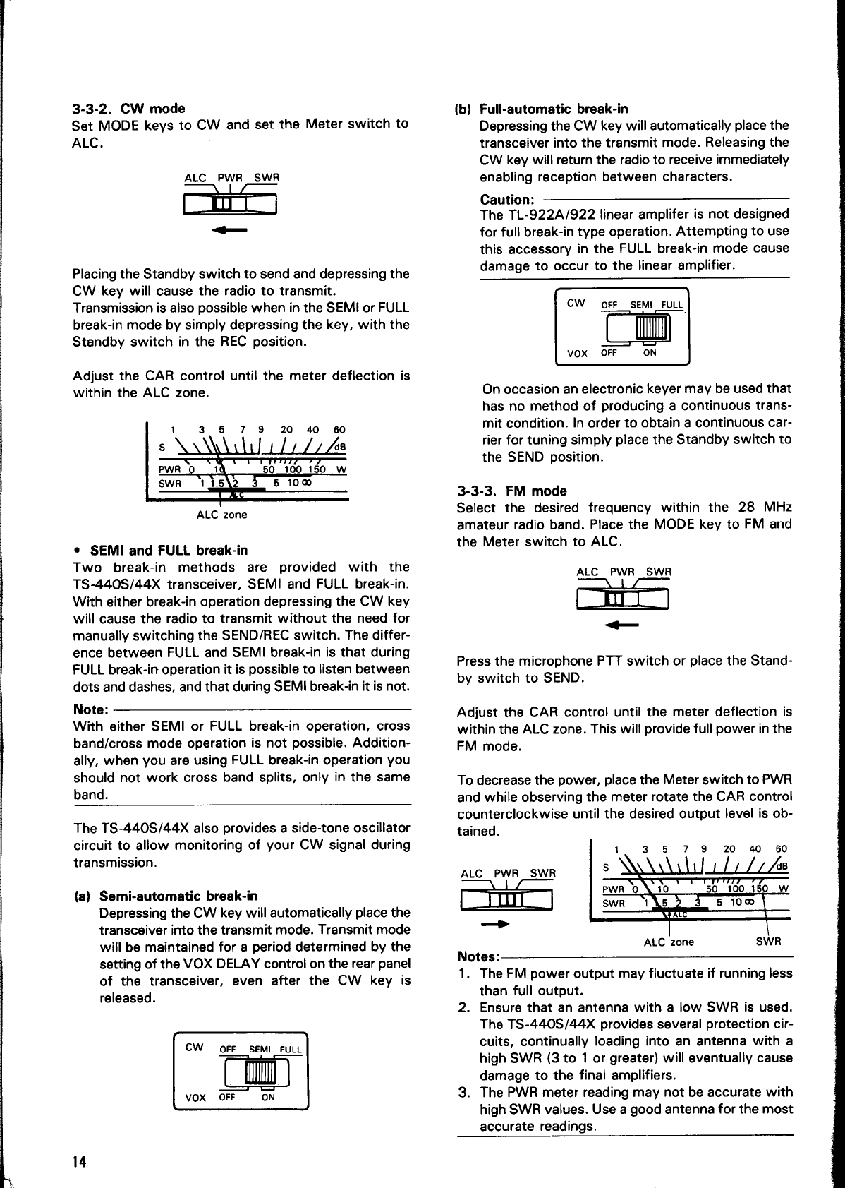
3-3-2.
CW
mode
Set
MODE
keys
to
CW
and
set
the
Meter
switch
to
ALC.
ALC
PWR
SWR
DB
Placing
the
Standby
switch
to
send
and
depressing
the
CW
key
will
cause
the
radio
to
transmit.
Transmission
is
also
possible
when
in
the
SEMI
or
FULL
break-in
mode
by
simply
depressing
the
key,
with
the
Standby
switch
in
the
REC
position.
Adjust
the
CAR
control
until
the
meter
deflection
is
within
the
ALC
zone.
1
3.5
7 9
20
40
60
x
Y”T'TTrTT7J
77
50
100
150
W:
SWR
11512
3
5
1000
E
ALC
zone
°
SEMI
and
FULL
break-in
Two
break-in
methods
are
provided
with
the
TS-440S/44X
transceiver,
SEMI
and
FULL
break-in.
With
either
break-in
operation
depressing
the
CW
key
will
cause
the
radio
to
transmit
without
the
need
for
manually
switching
the
SEND/REC
switch.
The
differ-
ence
between
FULL
and
SEMI
break-in
is
that
during
FULL
break-in
operation
it
is
possible
to
listen
between
dots
and
dashes,
and
that
during
SEMI
break-in
it
is
not.
Note:
With
either
SEMI
or
FULL
break-in
operation,
cross
band/cross
mode
operation
is
not
possible.
Addition-
ally,
when
you
are
using
FULL
break-in
operation
you
should
not
work
cross
band
splits,
only
in
the
same
band.
The
TS-440S/44X
also
provides
a
side-tone
oscillator
circuit
to
allow
monitoring
of
your
CW
signal
during
transmission.
(a)
Semi-automatic
break-in
Depressing
the
CW
key
will
automatically
place
the
transceiver
into
the
transmit
mode.
Transmit
mode
will
be
maintained
for
a
period
determined
by
the
setting
of
the
VOX
DELAY
control
on
the
rear
panel
of
the
transceiver,
even
after
the
CW
key
is
released.
CW
OFF
SEMI
FULL
VOX
OFF
ON
14
(b)
Full-automatic
break-in
Depressing
the
CW
key
will
automatically
place
the
transceiver
into
the
transmit
mode.
Releasing
the
CW
key
will
return
the
radio
to
receive
immediately
enabling
reception
between
characters.
Caution:
The
TL-922A/922
linear
amplifer
is
not
designed
for
full
break-in
type
operation.
Attempting
to
use
this
accessory
in
the
FULL
break-in
mode
cause
damage
to
occur
to
the
linear
amplifier.
CW
orr
SEM!
FULL
LE
VOX
OFF
ON
On
occasion
an
electronic
keyer
may
be
used
that
has
no
method
of
producing
a
continuous
trans-
mit
condition.
In
order
to
obtain
a
continuous
car-
rier
for
tuning
simply
place
the
Standby
switch
to
the
SEND
position.
3-3-3.
FM
mode
Select
the
desired
frequency
within
the
28
MHz
amateur
radio
band.
Place
the
MODE
key
to
FM
and
the
Meter
switch
to
ALC.
ALC
PWR
SWR
—
Press
the
microphone
PTT
switch
or
place
the
Stand-
by
switch
to
SEND.
Adjust
the
CAR
control
until
the
meter
deflection
is
within
the
ALC
zone.
This
will
provide
full
power
in
the
FM
mode.
To
decrease
the
power,
place
the
Meter
switch
to
PWR
and
while
observing
the
meter
rotate
the
CAR
control
counterclockwise
until
the
desired
output
level
is
ob-
tained.
ALC
PWR
SWR
—
ALC
zone
SWR
Notes:
1.
The
FM
power
output
may
fluctuate
if
running
less
than
full
output.
2.
Ensure
that
an
antenna
with
a
low
SWR
is
used.
The
TS-440S/44X
provides
several
protection
cir-
cuits,
continually
loading
into
an
antenna
with
a
high
SWR
(3
to
1
or
greater)
will
eventually
cause
damage
to
the
final
amplifiers.
3.
The
PWR
meter
reading
may
not
be
accurate
with
high
SWR
values.
Use
a
good
antenna
for
the
most
accurate
readings.

nc)
°
Subaudible
tone
An
optional
subaudible
tone
unit
TU-8
is
available
for
installation
in
the
TS-440S/44X
for
accessing
10
meter
FM
repeaters.
This
tone
is
activated
whenever
the
TS-440S/44X
is
in
the
SPLIT
mode.
3-3-4.
AM
mode
1.
Set
the
Meter
switch
to
PWR.
2.
Set
the
MODE
key
to
AM.
3.
Place
the
Standby
switch
to
SEND.
4.
Adjust
the
CAR
control
so
that
the
meter
indicates
25
watts.
Place
the
Meter
switch
to
ALC.
Adjust
the
MIC
gain
control
so
that
the
meter
deflection
does
not
exceed
ALC
zone
on
voice
peaks.
9m
3-4.
AUTOMATIC
ANTENNA
TUNER
(The
AT
unit
AT-440
is
required
for
this
function.)
The
automatic
antenna
tuner
operates
within
the
amateur
radio
bands
from
3.5
thru
29.7
MHz.
1.
Ensure
that
an
antenna
designed
for
use
within
the
band
you
intend
to
operate
on
is
properly
connect-
ed
to
the
antenna
terminal.
2.
Set
the
AUTO/THRU
switch
to
the
AUTO
position.
3.
Place
the
AT
TUNE
switch
to
the
ON
position.
The
AT
TUNE
indicator
will
light
and
the
tuner
will
be-
gin
tuning.
Then
the
CW
mode
indicator
will
light.
4.
After
a
short
period
the
AT
TUNE
indicator
will
go
OFF
and
the
motors
will
stop
turning.
5.
Place
the
AT
TUNE
switch
to
OFF.
6.
Tuning
is
now
completed.
You
may
now
carry
out
normal
communications.
Notes:
1.
When
the
AT
TUNE
switch
is
ON
and
the
AT
indi-
cator
lights
but
then
goes
out
immediately
it
is
an
indication
that
the
antenna
was
not
that
far
off
resonance
and
that
tuning
has
been
completed.
2.
Normal
operation
is
not
possible
until
the
AT
TUNE
Switch
has
been
turned
OFF.
3.
If
the
motors
do
not
stop
turning
after
approximately
30
seconds,
place
the
AT
TUNE
switch
to
OFF,
and
then
back
to
ON
again.
The
tuner
will
attempt
to
tune
again,
and
should
find
a
good
match.
If
the
tuner
will
not
stop
after
several
tries
it
indicates
some
problem
exists
with
the
antenna
system.
Readjust
the
antenna
and
feedline
before
attempt-
ing
to
tune
ágain.
3-5.
DUAL
DIGITAL
VFO's
Operational
convenience
can
be
enhanced
thru
the
use
of
both
VFO
A
and
VFO
B.
3-b-1.
Why
two
VFO's
Occasionally
DX
stations
will
utilize
an
operational
procedure
known
as
split
frequency
operation.
When
the
DX
station
is
in
this
mode
he
will
be
transmitting
on
one
frequency
and
receiving
on
another.
This
is
done
in
order
for
the
DX
station
to
be
able
to
recog-
.
nize
the
calls
of
stations
during
pile-ups.
Older
transceivers
required
the
use
of
an
external
VFO
to
allow
this
split
frequency
operation.
The
TS-440S/44X,
thru
the
use
of
microprocessor
controls,
effectively
provides
two
separate
VFOs
in
the
same
package.
Several
different
controls
and
switches
have
been
provided
to
increase
the
operators
convenience
when
faced
with
this
type
of
operation.
The
use
of
these
controls
is
discussed
below.
3-5-2.
Split
frequency
(a)
A=B
switch
Depressing
this
switch
causes
the
data
contained
in
the
inactive
VFO
(the
VFO
that
is
not
currently
being
displayed)
to
change
to
the
same
data
con-
tained
in
the
active
VFO
(the
one
currently
dis-
played).
Both
the
frequency
and
mode
are
changed.
For
example:
VFO
A
is
set
at
7
MHz
in
LSB,
and
VFOB
is
21
MHz
in
USB.
VFO
A
is
the
active
VFO
(show
on
the
display).
Depressing
the
A
=
B
switch
will
cause
VFO
B
to
change
to
7
MHz
in
LSB.
(b)
A/B
switch
Allows
selection
of
the
desired
active
VFO.
Each
time
this
switch
is
depressed
the
active
VFO
will
alternate
between
VFO
A
and
VFO
B.
(c)
SPLIT
switch
Allows
the
use
of
one
VFO
for
transmit,
and
the
other
for
receive
(Split
Frequency
operation).
For
example:
VFO
A
is
the
active
VFO,
and
VFO
B
is
the
inactive
VFO.
Depressing
the
SPLIT
switch
will
cause
the
TS-440S/44X
to
receive
on
VFO
A
and
transmit
on
VFO
B.
The
mode
of
reception
and
transmission
will
follow
the
mode
contained
in
the
appropriate
VFO
memory.
It
is
possible
to
work
cross
band,
cross
mode
if
desired.
To
avoid
confusion
during
contest,
or
pile-up
oper-
ations
we
recommend
using
VFO
A
for
receive
and
VFO
B
for
transmit.
(d)
T-F
SET
switch
Depressing
this
switch
will
allow
you
to
rapidly
set
or
check
the
transmit
frequency,
during
SPLIT
operations,
without
the
need
of
actually
trans-
mitting.
This
switch
is
especially
convenient
when
you
are
trying
to
locate
the
transmit
frequency
of
the
sta-
tion
currently
in
contact
with
the
DX
station,
since
15
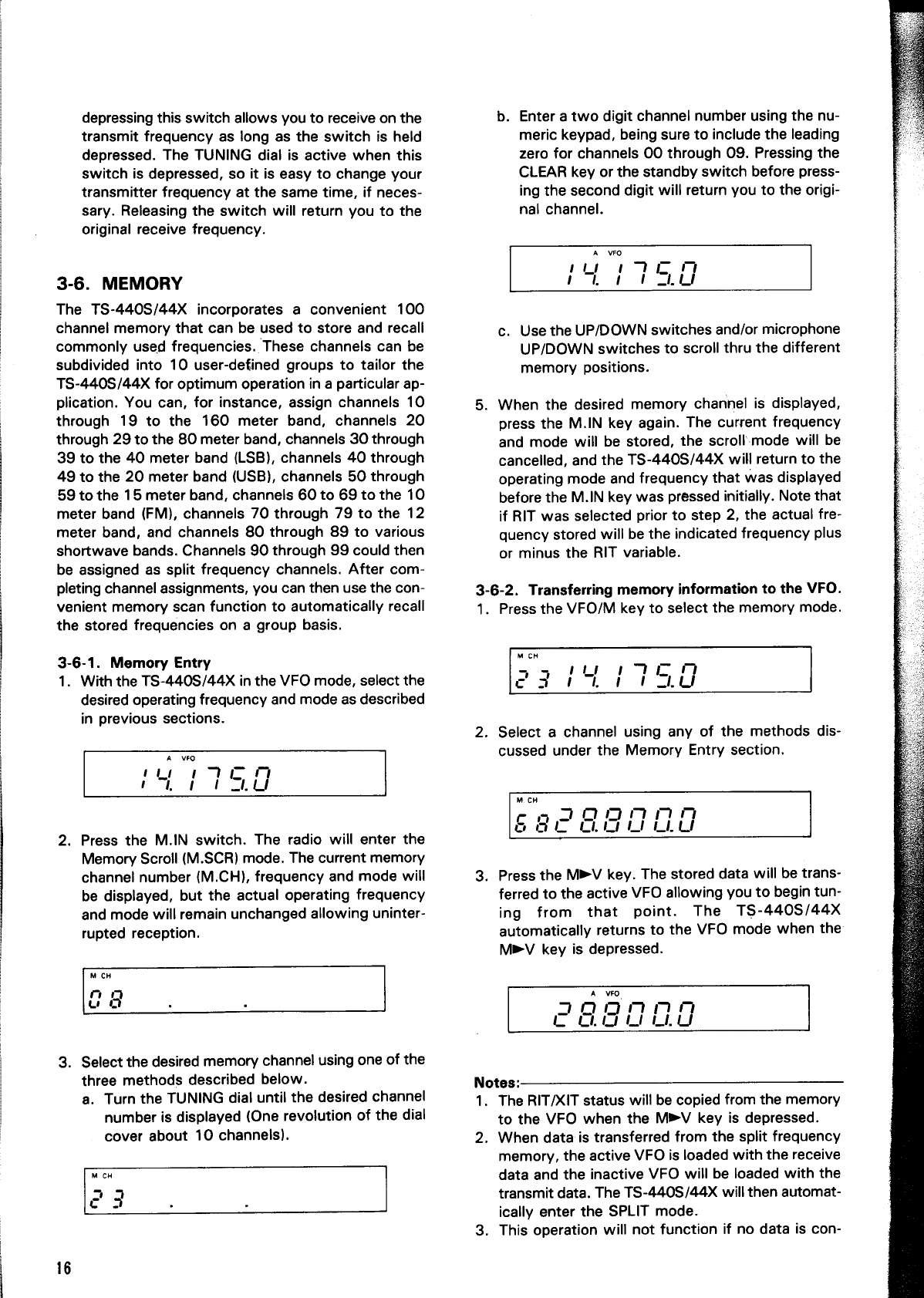
depressing
this
switch
allows
you
to
receive
on
the
transmit
frequency
as
long
as
the
switch
is
held
depressed.
The
TUNING
dial
is
active
when
this
switch
is
depressed,
so
it
is
easy
to
change
your
transmitter
frequency
at
the
same
time,
if
neces-
sary.
Releasing
the
switch
will
return
you
to
the
original
receive
frequency.
3-6.
MEMORY
The
TS-440S/44X
incorporates
a
convenient
100
channel
memory
that
can
be
used
to
store
and
recall
commonly
used
frequencies.
These
channels
can
be
subdivided
into
10
user-defined
groups
to
tailor
the
TS-440S/44X
for
optimum
operation
in
a
particular
ap-
plication.
You
can,
for
instance,
assign
channels
10
through
19
to
the
160
meter
band,
channels
20
through
29
to
the
80
meter
band,
channels
30
through
39
to
the
40
meter
band
(LSB),
channels
40
through
49
to
the
20
meter
band
(USB),
channels
50
through
59
to
the
15
meter
band,
channels
60
to
69
to
the
10
meter
band
(FM),
channels
70
through
79
to
the
12
meter
band,
and
channels
80
through
89
to
various
shortwave
bands.
Channels
90
through
99
could
then
be
assigned
as
split
frequency
channels.
After
com-
pleting
channel
assignments,
you
can
then
use
the
con-
venient
memory
scan
function
to
automatically
recall
the
stored
frequencies
on
a
group
basis.
3-6-1.
Memory
Entry
1.
With
the
TS-440S/44X
in
the
VFO
mode,
select
the
desired
operating
frequency
and
mode
as
described
in
previous
sections.
2.
Press
the
M.IN
switch.
The
radio
will
enter
the
Memory
Scroll
(M.SCR)
mode.
The
current
memory
channel
number
(M.CH),
frequency
and
mode
will
be
displayed,
but
the
actual
operating
frequency
and
mode
will
remain
unchanged
allowing
uninter-
rupted
reception.
M
CH
[E
o
3.
Select
the
desired
memory
channel
using
one
of
the
three
methods
described
below.
a.
Turn
the
TUNING
dial
until
the
desired
channel
number
is
displayed
(One
revolution
of
the
dial
cover
about
10
channels).
16
b.
Enter
a
two
digit
channel
number
using
the
nu-
meric
keypad,
being
sure
to
include
the
leading
zero
for
channels
OO
through
09.
Pressing
the
CLEAR
key
or
the
standby
switch
before
press-
ing
the
second
digit
will
return
you
to
the
origi-
nal
channel.
c.
Use
the
UP/DOWN
switches
and/or
microphone
UP/DOWN
switches
to
scroll
thru
the
different
memory
positions.
5.
When
the
desired
memory
channel
is
displayed,
press
the
M.IN
key
again.
The
current
frequency
and
mode
will
be
stored,
the
scroll:mode
will
be
cancelled,
and
the
TS-440S/44X
will
return
to
the
operating
mode
and
frequency
that
was
displayed
before
the
M.IN
key
was
pressed
initially.
Note
that
if
RIT
was
selected
prior
to
step
2,
the
actual
fre-
quency
stored
will
be
the
indicated
frequency
plus
or
minus
the
RIT
variable.
3-6-2.
Transferring
memory
information
to
the
VFO.
1.
Press
the
VFO/M
key
to
select
the
memory
mode.
2.
Select
a
channel
using
any
of
the
methods
dis-
cussed
under
the
Memory
Entry
section.
3.
Press
the
MV
key.
The
stored
data
will
be
trans-
ferred
to
the
active
VFO
allowing
you
to
begin
tun-
ing
from
that
point.
The
TS-440S/44X
automatically
returns
to
the
VFO
mode
when
the
MEN
key
is
depressed.
20
ann
agung
Notes:
1.
The
RIT/XIT
status
will
be
copied
from
the
memory
to
the
VFO
when
the
MV
key
is
depressed.
2.
When
data
is
transferred
from
the
split
frequency
memory,
the
active
VFO
is
loaded
with
the
receive
data
and
the
inactive
VFO
will
be
loaded
with
the
transmit
data.
The
TS-440S/44X
will
then
automat-
ically
enter
the
SPLIT
mode.
3.
This
operation
will
not
function
if
no
data
is
con-

tained
in
the
displayed
memory
channel.
4.
Data
in
the
VFO
is
replaced
by
the
memory
data.
Memory
data
is
not
lost
during
this
operation.
3-6-3.
Transferring
data
between
memory
channels
1.
With
the
TS-440S/44X
in
the
memory
mode,
press
the
M.IN
key
and
scroll
to
the
channel
that
you
want
the
data
to
be
transferred
to.
2.
Press
the
M.IN
key.
The
frequency
and
mode
of
the
memory
channel
that
appeared
before
you
pressed
the
M.IN
key
will
duplicated
in
the
new
channel.
3-6-4.
Entering/Transferring
data
in
the
split
fre-
quency
channels
Separate
transmit
and
receive
frequencies
may
be
en-
tered
into
memory
channels
90
through
99.
The
proce-
dure
is
similar
to
that
given
for
the
other
channels
with
the
following
exception:
1.
The
active
VFO
frequency
and
mode
is
stored
in
the
receive
memory,
and
the
inactive
VFO
frequen-
cy
and
mode
is
stored
in
the
transmit
memory,
regardless
of
whether
the
SPLIT
function
is
ON
or
OFF.
2.
The
RIT
offset
is
stored
in
the
receive
memory,
and
the
XIT
offset
in
the
transmit
memory.
3.
When
data
is
transferred
from
the
general
memory
section
into
the
split
frequency
memory
section
the
transmit
and
receive
frequencies
will
be
the
same.
4.
Only
the
receive
memory
will
be
transferred
into
general
memory
during
transfer
operations
from
the
split
memory
area.
3-6-5.
Clearing
a
memory
channel
Two
methods
may
be
used
to
clear
a
memory
channel:
1.
M.IN
switch
Transferring
information
from
a
vacant
channel,
i.e.
one
that
has
no
stored
information,
thru
the
use
of
the
M.IN
switch,
as
described
previously
in
section
3-6-1
is
one
method
of
‘‘clearing’’
a
memory
channel.
2.
ENT
switch
Data
may
also
be
erased
by
depressing
the
ENT
key
while
depressing
the
CLEAR
key.
3-6-6.
Memory
recall
Fixed
channel
type
recall
is
possible
when
using
the
VFO/M
key
to
recall
memory
channel
information.
The
stored
frequency
cannot
be
changed,
although
the
RIT/XIT
function
is
active.
1.
Press
the
VFO/M
key.
The
memory
channel
num-
ber,
mode,
and
stored
frequency
data
will
be
dis-
played.
If
a
channel
contains
no
data,
only
the
channel
number
will
be
displayed.
>
Sd
"uu
LA
Bn
2.
Select
the
desired
memory
channel
using
the
methods
described
under
Memory
Entry
section.
Pee
Sd
3.
To
return
to
the
VFO
mode,
press
the
VFO/M
key
again.
Notes:
1.
RIT/XIT
will
be
cancelled
when
the
TS-440S/44X
is
switched
from
the
VFO
mode
to
the
memory
mode,
but
will
be
restored
when
the
TS-440S/44X
returns
to
the
VFO
mode.
2.
When
the
TS-440S/44X
is
switched
from
the
memory
mode
to
the
VFO
mode,
the
VFO
will
be
set
to
the
RIT/XIT
variable
specified
when
the
data
was
programmed
in
to
memory.

3-7.
SCAN
3-7-1.
Memory
scan
Memory
scan
operates
from
memory
channel
00
thru
memory
channel
99
at
approximately
3-4
second
in-
tervals.
Only
those
memory
channels
with
data
entered
are
scanned.
To
initiate
memory
scan
1.
Press
the
VFO/M
key
to
select
the
memory
mode.
Example
1
Group
2
CH20 CH29
—
A
i
L-
~
EI
Example
2
Group
1
Group
2
CH10
CH19
CH30
CH39
2.
Press
the
SCAN
key.
Scan
will
begin
at
memory
channel
OO,
or
the
lowest
numbered
channel
con-
taining
data.
3.
You
can
stop
scanning
by
pressing
the
CLEAR
or
microphone
PTT
switch.
Pressing
the
PTT
switch
will
allow
you
to
continue
scanning
from
the
point
that
you
stopped,
and
pressing
the
CLEAR
key
will
allow
you
to
start
scanning
from
the
beginning.
4.
To
resume
scan
press
the
SCAN
key
again.
3-7-2.
Program
scan
Two
programmable
scan
ranges
are
provided
on
the
TS-440S/44X
transceiver.
PG.S-1
(Program
Scan
range
1)
utilizes
memory
channels
O6
and
07
to
specify
the
upper
and
lower
scan
limits.
PG.S-2
(Program
Scan
range
2)
utilizes
memory
channels
08
and
O9
to
specify
the
upper
and
lower
scan
limits.
Example
[9
—
P8.8-1—————]
CHO6
CHO7
14.010.0CW
—
14.100.0USB
[
—
—
——
PG.s-2
—
—
—34
CHO8
CHO9
14.200.0USB
—
14.320.0AM
18
Monitor
display
To
initiate
PG.S-1
1.
Press
the
VFO/M
key
to
select
VFO
mode
operation.
2.
To
begin
scan
press
the
SCAN
key.
Scan
will
be-
gin
at
channel
number
06
and
proceed
in
10Hz
(USB/LSB/CW/AFSK),
100Hz
(AM/FM)
steps
towards
channel
07.
Example
ü)
L—PGS-1—4
ro
PG.S-2
—n
H
H9
14,010,
00
H
14,
200,
00
14,
100,
00
14,
320,
00
cw
or
USB
La-
4
t---------
4
(ii)
PG.S-1
PG.S-2
he
d
em?
r
`
mm
CH7
CH8
CH9
3.
To
stop
scanning
press
the
PTT
switch,
or
the
CLEAR
key.
Pressing
the
SCAN
key
allows
scan
to
resume
from
the
point
you
stopped.
3-8.
AFSK
3-8-1.
Reception
Note:
An
RTTY
terminal
is
required
to
receive
and
dis-
play/print
the
RTTY
signal.
1.
The
AFSK
mode
utilizes
the
LSB
carrier
frequency,
which
conforms
to
international
conventions.
2.
When
the
optional
YK-88C
filter
is
installed,
the
nor-
mal
receiver
bandwidth
is
500
Hz
when
the
SELEC-
TIVITY
switch
is
set
to
the
AUTO
position,
and
the
MODE
switch
is
in
AFSK.
The
accompanying
diagram
illustrates
the
relation-
ship
between
the
carrier
and
the
passband
width.
3.
The
demodulated
AFSK
signal
is
sent
from
the
AFSK
ỌUT
terminal
on
the
rear
panel.
4.
This
completes
the
preparation
for
using
the
AFSK
mode.
Notes:
1.
Before
connecting
the
terminal
you
should
review
the
contents
of
the
instruction
manual
provided
with
that
terminal
unit.
2.
For
AMTOR
reception,
you
should
use
AFSK
in
the
USB
mode.
AFSK
IN
AFSK
keying
signal
Pu
bw
aa
RTTY
wave
(F1)
RTTY
device
AFSK
receive
signal
AFSK
OUT
Other manuals for TS-440S
1
Table of contents
Other Trio Transceiver manuals


