Introduction
The Lancast 6221/6224 Series Fast Ethernet Transceiver provides
100Mbps connectivity for desktop PCs and servers as well as
bridges and servers.
Inspect your order carefully. If you discover any shipping damage,
notify the carrier and follow their instructions for damage and
claims. Be sure to save the original shipping carton should return
or storage of the unit be necessary.
Installation
The transceiver mounts directly to a 100Mbps Ethernet card, server
(DTE), or other device with an IEEE 802.3u compliant 40-pin MII
interface. In situations where it is not possible to connect directly
to the MII port, a short MII cable (0.5m) may be used.
The following network connections are supported:
6221-01 ________ 100BASE-FX multimode SC connector
6221-02 ________ 100BASE-FX multimode ST connector
6221-03 ________ 100BASE-FX singlemode SC connector
6221-04 ________ 100BASE-FX multimode VF-45 connector
6221-06 ________ 100BASE-FX multimode MT-RJ connector
6221-07 ________ 100BASE-FX singlemode MT-RJ connector
6224 ________ 10/100BASE-TX RJ-45 connector
LED Operation
There are five LEDs on each transceiver for indication of normal network
operation and network diagnostics. Upon proper installation of the
transceivers, the LEDs illuminate as follows:
PWR (Power) __ green (steady) indicates the transceiver is receiving
power from the attached DTE.
LINK _________ green (steady) illuminates only when there is a valid
connection.
TX (Transmit) __ green (blinking) indicates the transceiver is
transmitting information.
RX (Receive) ___ green (blinking) indicates the transceiver is
receiving information.
COL (Collision)_ Half-duplex mode: amber (steady) indicates that
data is simultaneously detected on both the RX and
TX ports at the same time;
Full-duplex Mode: does not illuminate.
DIP Switch Operation
The four-position DIP switch provides greater network configurability and
improved interoperability options. Refer to the appropriate section for your
type of transceiver:
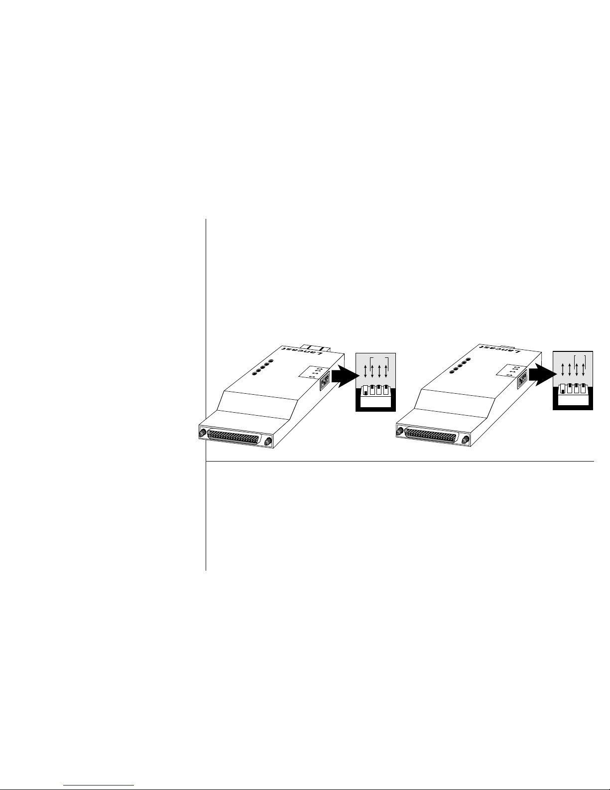
6221 Series 100BASE-FX Transceiver
Switch 1 permits you to choose between full- or half-duplex operation:
• UP = Half-duplex mode
• DOWN = Full-duplex mode
Switches 2, 3, and 4 permits you to specify a PHY address. The PHY
settings are binary and switch 2 represents the least significant bit (LSB).
The transceiver is shipped from the factory with a PHY address of “0” (i.e.
switches 2, 3, and 4 are in the UP position). Refer to the illustration. To set
a PHY address of “1,” set switch 2 in the DOWN position).
6224 10/100BASE-TX Transceiver
For greater network flexibility, switch 1 permits you to select the speed of
the unit:
• UP = 10 Mbps
• DOWN = 100 Mbps
Switch 2 permits you to choose between full or half duplex:
• UP = Half duplex
• DOWN = Full duplex
Switches 3 and 4 permits you to specify a PHY address. The PHY settings
are binary and switch 3 represents the least significant bit (LSB). The
transceiver is shipped from the factory with a PHY address of “0” (i.e.
switches 3 and 4 are in the UP position). Refer to the illustration. To set a
PHY address of “1,” set switch 3 in the DOWN position).
1
Half PHY
Configuration
Full
234
0
1
0
1
0
1
PWR
LNK
TX
RX
COL
Configuration
Half000
PHY
Full111
Warranty and Servicing Information
METRObility Optical Systems, Inc., warrants the 6221 and 6224 Fast Ethernet Transceivers to be in good working order for the period of THREE YEARS
from the date of METRObility shipment. Should the unit fail anytime during said three-year period, METRObility will, at its option, replace or repair the
product. This warranty is limited to defects in workmanship and materials and does not cover damage from accident, disaster, misuse, abuse or unauthorized
modifications. Under no circumstances will METRObility be liable for any damages incurred by the use of this product including, but not limited to, lost
profits, lost savings, and any incidental or consequential damages arising from the use of, or inability to use, this product.
If the product was purchased from an authorized METRObility dealer, limited warranty service may be obtained by returning the product to the dealer.
Return the product in its original shipping container (or equivalent), pre-insured, and with proof of purchase.
Safety and EMC
METRObility products have been approved by applicable US and international regulations: UL, C-UL, CSA, TUV, FCC, CE.
This product shall be handled, stored and disposed of in accordance with all governing and applicable safety and environmental regulatory agency
requirements.