Trio TS-530SP User manual

TF?IO TS-530SP
HF TFIANSCEIVEFI
INSTRUCTION
MANUAL
This instruction manual covers TS-S3OSP and TS-S3OD. lf
instructions differ from each other, thoae are mentioned
separately.
Please refer to an instruction corresponding to your type of
transceiver.
AFTER
UNPACKING
Savethe original
boxespacking
in the event your unit WARNING:
needsto be transportedfor remote operation,mainten- Personal
injury
may
occur
- do
notdisregard.
ance,
orservice.
Thefollowing
explicitdefinitions
applyinthismanual.
Be CAUTIoN:
.@__-
sureto read
thesedefinitions:
NOTE:
lfdisregarded,
inconvenience
only
- no
damage
or
person- WARNINC
alinjury.
Read
OperatingManual
Section4. before
placing
trd|3rnrner,n
servrce.
HIGH
VOLTAGES
PRESENT.
CAUTION:
Equipment
damagemay
occur.butnotpersonal
injury.
SPEC|FICAT|ONS........... 3 4.3 Transmission
(t)
SECTION1.INTRODUCTION
ANDFEATURES........
4 (1)SSBOperation
SECTfON2.fNSTALIAT|ON........... 5 4.4 Transmission
(il)
2.1 Unpacking (1) Speech
processor
2.2 OperatingLocation (2) VOX
(Voice
OperatedTransmit)
Operatron
2.3 Cabling (3) XIT(Transmitter
Incremental
Tuning)
2.4 Microphone (4) CWOperation
2.5 Key 4.5 DigitalDisplay
Calibration
2.6 External
speaker
and
Headphones 4.6 Analog
Dialcalibration
2.7 Ground sEcrtoN
5.
oprtoNALAccEssoRtEs............
.......
20
2.8 Antenna 5.1 OptionalAccessories
SECTION3. CONTROLS
AND THEIRFUNCTIONS. 8 5.2 Installation
of
Accessories
3.1 FrontPanel SECTION6.
MAINTENANcEANDALIGNMENT....2S
3.2 RearPanel 6.1 General
SECTION4. OPERATION............. .........
14 6.2 Service
Position
4.1 Reception
(l) 6.3 Receiver
Adjustments
(1) BasicProcedures
for Receive
Operation 6.4 Transmitter
Adjustments
(2) WWV Reception 6.5 Transmitting
onWARCBANDS
4.2 Reception(ll) 6.6 Operation
on22OYACoT24OVAC(USA)
(1) NOTCHCONTROL SECTTON7.TROUELESHOOTTNG ........
28
(2)
RFATTSwitch BLOCKDIAGRAM... ...........29
(3)
RFGainControl |NTERNALV|EW............. ........................
30
(4)
AGC
(Automatic
GainControl) SCHEMATICDIAGRAM ........................
31
(5)
RrT/XrT
(6)
rF
Shift
(7) NARROW
Switch
(8) NoiseBlanker
(NB)
CONTENTS
el

TS-53OSPECIFICATIONS
[GENERAL]
Frequency
Range.......... 160mBand 1.8
'- 2.0MHz
8Om Band 3.5 - 4.0MHz
40 mBand 7.0- 7.3MHz
30mBand
10.1
- 10.1
5MHz
(1O.0
MHzWWV)
20 mBand
14.O
- 14.35
MHz
17mBand18.068
- 18.168
MHz
1
5 mBand
21.O
- 21
.45MHz
12m Band
24.89
- 24.99
MHz
1Om Band28.O
- 29.7MHz
SSB/CW
Within'l kHzduring
thefirst
hourafter
1minuteofwarmup.
Within100 Hzduringany30 minute
period
thereafter.
11
0VAC/1
20VAC|240VAC,
50/60 Hz
Transmit:
295 watts
Receive:
27 watts (withheatersoff)
333
(13.3)x
133
(5.3)x
333
(13.3)
mm
(inch)
12.8kg
(28.2
lbs)
Modes.........
FrequencyStability
......
PowerRequirement
...................
Power
Consumption
..................
Dimensions
Weight........
[TRANSMITTER]
* FinalPower
Input.........
Audio
Input
lmpedance
............
RF
Output lmpedance..
CarrierSuppression
Sideband
Suppression
Spurious
Radiation....
Harmonic
Radiation
AudioFreq.Response..............
ALCInput
LinearAmp RelayContact
Ratin9..........
IRECETVERI
ReceiverSensitivity
lmageRatio............
lF Rejection
Receiver
Selectivity
ssB/cw.....
Notch-filter Attenuation
AudioOutput lmpedance
AudioOutput
NOTE:
The circuitand ratings
technology.
TS-53OD
160W PEPforSSB
operation
13OW
DCforCWoperation
500p - 50 kjz
50Q - 75r/
Betterthan
40 dB
Better
than50 dB
Betterthan60 dB
Betterthan
40 dB
4OOto 2,600
Hz.
within
-6 dB
-1OV
DCMax
100vDc1A
O.25
uV
at10dBS
+N/N
Betterthan6O
dB
Betterthan70 dB
2.4kHz
(-6 dB),
4.2kHz
(-60 dB)
CWOptional
Filter
YK-88C5OO
Hz
(-6 dB),
1.5kHz
(-60 dB)
YK-88CN
27OHz
(-6
dB),
1.1kHz
(-60
dB)
SSBOptional
Filter
YK-88SN1.8
kHz
(-6
dB),3.3
kHz
(-60
dB)
Betterthan
20dB
(1
.5kHz)
8 - 16(2
1.5W
(8l2)
may be changed
without noticedueto developments
TS_530SP
__
22OWPEP
for
SSB
operation
18OWDC
for
CWoperation

SECTION
1.INTRODUCTIONAND
FEATURES
1.1KENWOOD
TS-530
TheTS-530 is highlysophisticatedsolidstateAmateur
band
transceiver
employingonlythree
vacuumtubes.
Operating
on all Amateurbandsbetween1.8 and 29.7
MHz,
this unit is constructed
modularly.
TheTS-530 in-
cludesmany built-infeaturesusuallyfound as extrason
other transceivers.Included
are VOX. 25 kHz calibrator,
RlT, RF attenuator,
and an effective noise blanker. The
TS-530also
includes
automatic
gain
control
(AGC),
auto-
maticlevelcontrol(ALC),
semi-break-inCWwith sidetone,
aspeech
processor,
speakerand
built-inACpower
supply.
Any complicated electronic device will be damaged if
operated
incorrectly.
and
thistransceiver
isnoexception.
Pleasereadallof the operatinginstructions
before
putting
your
TS-530 onthe air.
1.2FEATURES
1. Interference-free
DXoperation
* TUNABLENOTCH
FILTER
Interferenceis reducedor eliminatedusing
thebuilt-in
notchcircuit.TheTS-53OusesanAudionotchfilter.
' lFshiftcircuit
The lF SHIFTis a circuit to shift lF pass-bandwidth
without changing
receivefrequency. lt eliminates
in-
terferenceor adjustsreceivefrequency
characteristic
asdesired.
* NARROW/WIDE
BAND
WIDTHselectionandoptional
filtersfor enhanced
operation.
NARROW or WIDE
CW operationcanbe selectedwhen usingoneof two
optional
filters:
YK-88C
(5OO
Hz)or YK-88CN
l27OHzl
NARROWor WIDE SSB operation can be selected
whenusing
theoptionalYK-88SN
(1.8
kHzlfilter.
2. WARC
bands
The TS-53O fully covers the 16O-1Om
Amateur
bands,
including
thenewWARC
bandsof 1O.
18 and
245 MHz. The
VFOcoversat least5OkHzabove
and
beloweach50OkHzband. Theoptional
VFO-230ex-
ternal
digital
VFOcoversabout 1OO
kHzabove
and
beloweach
band,
forMARSand
otherapplications.
3. All-in-one,compact
ACPowersupply.
4. Advanced circuit design for improved two-signal
characteristics.Cleverly
designed
front-end circuit
componentsand receivecircuit systemassureexcel-
lenttwo-signalcharacteristics.
Cross-modulation
and
blockingarereduced.
5. TXfinalunituses61468's/S2OO1A.
The final transmittingtubesare: two 61468's two
6146B's,61468's/S2OO/AS
for the TS-530SP;on
S2OO1
A fortheTS-530D.
AmplifiedALC provides
clear,strong signals
with re-
ducedcross
modulation.
6. Variable
levelnoise
blanker
Conventional
fixed
levelnoise
blankersare
sometimes
lessthan effectivein removingpulsatingnoiseover
weak signals
or rejecting
strong interference
signals.
This
variablelevel
noiseblanker
isequipped
to control
theoptimum
threshold
levelof the gate
pulse
ampli-
fier.
7. Thespeech
processor
controlsthe audiocompression
level
and ALC time constant to increasethe average
audio
levelandtransmitpower.
8. XIT(Transmit
lncrementalTuning)for fine adjustment
of transmit frequency independentof receive fre-
quency.
9. Built-in
digitaldisplay
Displays
accuratefrequenciesto the 1OOHz order,
anybandor mode.
1O.The controlsarearrangedon the zincdie-castfront
panel
for easyoperation.
11. A fullvariety
of accessory
circuitsareprovided:
TheTS-530includes:
VOX circuit (available
for Semi-Break
in),Markercir-
cuit,side-tone
oscillator,selectable
AGC(OFF.
FAST,
SLOW) RF Attenuator. CW zero-beatcircuit (in the
Tune position), HEATER switch. SCREEN GRID
switch,andbuilt-in
speaker.

SECTION
2.INSTALLATION
2.1 UNPACKING
Remove
theTS-530
fromits
shippingcontainer
and
pack-
ing material
and examineit for visibledamage. lf the
equipmenthasbeendamaged
inshipment,notifythe trans-
portation company immediately.
Save the boxes and
packing
material
forfuture
shippingormoving.
The followingaccessories
shouldbe included
with the
tranceiver.
1. Instruction
Manual
(850-4076-OO)
....................
1
2. Plastic
ExtensionFeet
withScrews
(JO2-0049-14)
......... ..............
2
3. SpeakerPlug1/8"
(E1
2-OO01-05)
.....................
1
4. 7P
DINPlug
(E07-0751
-O5) ..........
1
5. Fuse
TS-S3OSP
(USA)
12OV 64.............1
r POWER
CONNECTIONS
Make
surethePOWER
switchonthefrontpanel
isturned
off,thestand-byswitchisintheREC
position,
andtheline
voltage
iscorrect.Then
connectthe POWER
cordto the
line
source.
r AC POWER TS-530SP
For
fixedstationoperation,the unitoperatesfrom 120V
AC (U.S.A.)
or 22OV AC|24OVAC (Europe),
5O/6OHz
power
sourcecapable
ofsupplying280 watts
ormore.
. 120V
AClinemodel
(U.S.A.)
A 64 fuseisused.
lf you desireoperation
on 22OV
AC or 24OV
AC,it is
necessaryto changethe power transformer
connec-
tions
andthe
fuse.
See
page
27.
. 12O|22OVACline
model
Thisversionis
equippedwith avoltage
selector
switch
on the rear
panel.
Setthe switchto yourline
voltage
andusethe correctfuse. 120V settingrequires
a 6,4
fuse.22OV
setting
requires
a44 fuse.
. 22O|24OVACline
model
(Europe)
This
destinationtypeisequippedwith a voltage
selec-
torswitchontherear
oanel.
A 44 fuseshouldbeused.
Settheswitchto your
linevoltage
andusethecorrect
fuse.
NOTE:
o The22O|24OVAC
modelis
preset
to 22OY.
o The12O|22OVAC
modelis
preset
to 22OV.
TS-530D
Forfixed
stationoperation,theunit
operates
either
11O
or
22OVAC,50/60Hz
powersource.
Check
your
local
linevoltage
beforeoperation.
The11OVAC
settingrequires
64 fuse.
The22OVAC
settingrequires44 fuse.
Note:
TheTS-530D
is
preset
to 110V
AC.
TS-53OSP
TS-53OSP
TS-530D
220/240V
44
...............
1
120l22OV
6/4A...1
each
11Ol22OV
6/4A...1
each
2.2 OPERATING LOCATION
As with anysolid
stateelectronic
equipment,
theTS-53O
should be kept from extremes
of heat and humiditv.
Choose
anoperatinglocation
thatisdryand
cool,and
avoid
operatingthetransceiver
indirectsunlight.
Also,allow
at
least
3 inches
clearance
between
the backof the equip-
ment to any object. This space
allowsan adequate
air
flow
fromtheventilating
fan
to keepthe
transceiver
cool.
CAUTION:
Donotoperatetheradio
inanRFField
greater
than
6V RF.
Receiver
damagemay
occur.
2.3 CABLING
(See
Figure
2-1.)
r GROUND
To
prevent
electricshock,
andreducethe
possivility
of
TVI
and
BCl,
connectthetransceiver
to a good
earth
ground
throughasshort
and
heavy
alead
as
possible.
Use
ground
rodsormetal
coldwaterfeedline.
NOTE:
A ground
connection
greater
than 1/4 ). awayfrom the
transceivermay be a good DC ground,
but NOTan RF
ground.
r ANTENNA
Connectthrough
a 50 ohm antennafeedlineto the coax-
ialconnector
ontherear
panel.
I KEY
lfCWoperationis
desired,connect
a keyto the KEY
jack.
Use
shieldedline
orcoaxialcable.

Headphones
Useheadphones
of 4 to 16O imPe-
dance.Theoptional
HS-4,
5, 6 or 7
headphones
bestsuited
for use
with
th€ TS-53O
Stereo-type
phones
can
also
beused.
Antenna
Surge
arrestor AL-2
Canbe used
for
TX monitor
Gl{D terminal
It is recommend€d
that aground lead
b€conn€cted
to the GND
terminal
at
the rearof the setto preventthe pos-
sibility
ofelectric
shock,
TVIandBCl.
Useas short and heavya leadasPos-
sible.
Microphone
Either
a low or high impedancemi-
crophone(5OOO
to 50 kO can be
used. The P.T.T.
switch should be
isolated
from th6 mic circuit
(shown
in "A"). Usea microphonewith ase-
oarate
switch and MIC line so both
P.T.T.
and
VOXareavailable.
,-<
n t--all E
r- o
trq
'^-ll
M'c'ooho.cl) P 9[
,--ll
| ^-tt 6-<
M,c,oeho..
u e____9ll
E
| -
I I'ansto'mc' O. --'
LinearamPlifier
MC-50
MC-60
External speaker
B€sides
the built-in speaker,
an
externalsDeaker
canalso
beused.
Connect to the rear EXT
SPjack usingthe supplied
ptu9.
sP-230
VFO-23O
or
vFo-2tto
\ t-::
Key
ForCW operation,
connect
Your
keY
to the KEY tack at the rear. Use
shielded
cable.
AC linesource
See
page5,AC POWER
6
EI
Fig. 2-1 TS-530 Connections
Extemal VFO
2.4 MICROPHONE
Attach the microphone
connector
to a suitable
micro-
phone,
as shown in Figure
2-1
. Besure
the microphone
PTTswitch is separate
from the microphone
circuit,as
shown. lt should
be notedthat a microphone
with a 3P
plug
usingacommon
ground
terminal
should
notbeused.
Themicrophone
input
isdesigned
for 50OO- 50kOmi-
crophones.
The choiceof microphone
is important
for
good
speech
quality,
andshould
begiven
seriousconsidera-
tion. The
crystal
lattice
filterin
thetransceiver
provides
all
the restriction
necessary
on audio
response,
andfurther
restriction
inthe
microphone
is
not
required.
lt ismoreim-
portant
to haveamicrophone
withasmooth,
flatresponse
throughout
thespeech
range.
Follow the microohone
manufacturer's
instructions
for
connecting
themicrophone
cableto the plug.
With many
microphones,
thepush-to-talk
switch
mustbepressed
to
makemicrophone
audio
available.
For
VOXoperation,
this
unwanted
feature
maybeeliminated,
if.desired,
by open-
ing
themicrophone
case
and
permanently
connecting
the
contacts
whichcontrol
themicrophone
audio.
Standard
microphone
sensitivity
is within the range
of
-50 dB
to -60 dB.lfa
microphone
havinga
highersen-
sitivity
is used,
the ALC
andcompressor
circuits
will not
function
properly.
Inthiscase,
insert
inthe
mikelineanat-
tenuator
asshown
inFig.
2-1c.A typical
MIC
gain
control
setting
is 12 o'clock.
lf youmustrunthiscontrol
at I o'-
clock
orless,useanattenuator.
2.5KEY
lf CW operation
isdesired,
connect
a key
to theKEY
jack.
Use
shielded
cable,and
a standard
(mono
or 2P)
phone
plug.
2.6 EXTERNAL SPEAKER AND
HEADPHONES
Receive
audiooutput
fromthe
TS-530is 1.5wattsat4 to
16 ohms.TheTS-530 hasa built-in
speaker
jackon the
rearpanel.The speaker
may be an 8-ohm permanent-
magnet
type,
4 inches
or'larger.
The internalspeaker
is
disconnected
when an external
speaker
is used. Head-
phones should also be 4 to 'l
6 ohms impedance
or
greater.
When headphones
are connected
to the front-
panel
PHONES
jack,
thespeaker
isdisabled.
2.7GROUND
Toorevent
electricshock,
and
reduce
the
possibility
ofTVI
and BCl,connect
the transceiver
to a good
earth
ground
through
asshortand
heavya leadas
possible.
2.8 ANTENNA
Anyof thecommon
antenna
systems
designed
for useon
the high
frequencyamateur
bands
maybe used
with the
TS-530
provided
theinput
impgdance
ofthetransmission
line
is
notoutside
thecapability
ofthebi-output
m3tching
network.The transmission
lineshould
be coaxial
cable.
An antenna
system
which
showsastanding
wave
ratioof
lessthan2:1
when
using
5Oor
75 ohmcoaxial
transmis-
sion
line,orasystem
that
resultsin a
transmission
line
in-
put impedance
that is essentially
resistive,andbetween
15 and 2OOohms will take powerfrom the transceiver
with littledifficulty.
lf openwireof balanced
type trans-
mission
lineisused
with theantenna,
a suitable
antenna
tuner
with balun
isrecommended
between
the
transceiver
and
thefeedline.
Methods
of construction
andoperating
such
tunersaredescribed
in detail
in the ARRL
Antenna
Handbook,and
similar
publications.Foroperation
on the
160,75 and
4Ometer
bands,asimple
dipoleantenna,
cut
to resonance
in the most used
portion
of the bands,
will
perform
satisfactorily.
Foroperation
of thetransceiver
on
the 10, 15 and20 meterbands,theefficiency
of thesta-
tion will be greatly
increased
if a gooddirectional
rotary
antenna
isused.Remember
thateven
the mostpowerful
transceiver
isuseless
without
aproper
antenna.
CAUTION:
Protect
your Equipment-Use
a LIGHTING
ARRESTOR.
TheTRIO
AL-2is
recommended.
SECTION
3. CONTROLS
ANDTHEIR
FUNCTIONS
@ruorcurNcrcAToR
LED
@vro
rnotcnroR
leo
@enocrNDrcAToRLED
@nrarr rNDrcAToRLED
@
cnl
swrrcu
@ueren
@vox
swrcn
@vox
eru
@r.rsswtrcn
@ruelevelcorurnol
@lccswrrcn
@rueren
swrrcH
@srnruo-av
swtrcH
o
@vox
oruv
@
can
lrvel coNrRoL
O
@eHones.llcr
@vrrc
cor.rruecron
@uoor
swrrcH
@utcclr.rcoNTRoL
@ruan
@enocswrcu
DIGITALDISPLAY
ANALOGDIALSCALE
MAINTUNING
LOADCONTROL
C)
PLATE
CONTROL
O
DRIVE
CONTROL
RIT/XIT
LED
RIT/XIT
CONTROL
@enruo
swrrcH
+0.5SWITCH
IF
SHIFT
CONTROL
@
@ruorcu
s\
/rrcH
xrTswlTcH
o
RrT
SWTTCH
@
@nrarr swrcn
6r
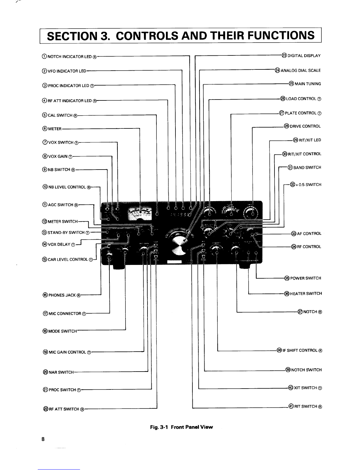
Fig.3-1 Front PanelView

3.1 FRONTPANEL
Thesymbolafterthepartnameindicates:
@:
Activeonlyduring
reception.
@:
Activeonlyduringtransmission.
Nosymbol:
Alwaysactive
1. NOTCHTNDTCATORLED
@
Thisindicator,
(light
emittingdiode).
illuminates
whenthe
NOTCHcircuit
is
tumedON.
2. VFOINDICATOR
TheVFOindicatorilluminates
whentheinternalVFOcon-
trols transceiveroperation. The indicator is not lighted
duringfixedchannelorremote
VFO
operation.
3. PROC
(SPEECH
PROCESSOR)
TNDTCATOR
O
Thisindicator,
(light
emittingdiode),illuminateswhenthe
PROCswitchisturnedON.
4. RF
ATT TNDTCATOR
@
ThisilluminateswhentheRFATTisturned
ON.
s.cALswrTcH
(R)
This
switchenergizes
the
built-inmarkercircuit.
Receive
frequency
can be calibratedat 25 kHz intervals
usingthisoscillator.
6. METER
The metermonitorsfive different
functions,dependingon
METER
switch position. In receive
the meterisautomati-
callyan S-meter,andshows received
signalstrengthon a
scaleof O to 4O dB over 59. In transmit,meterfunction
depends on the position of the METER
switch, as de-
scribedbelow. This is an average-respondingmeter,NOT
peak.reading.
7. VOXSWTTCH
O
The VOX circuit is readied
for voiceoperated
transmit in
SSBor semi-break-inCW.
8. VOX GA|N O
This controls sensitivity of the VOX (Voice Operated
Transmit)circuit.
9. NBSWTTCH
@
With the pushswitch lN,the noiseblankercircuitturned
ONreducing
pulse-type
(ignition)
noise. Power-line,radat
QRMandatmospheric
"white" noiseswill not operatethe
blanker.Thenoise
blankercircuitoperatinglevel
isadjus-
tablebythe noiseblanker
control.
10. NBLEVELCONTROL@
This control adjusts the noise blanker circuit operation
level
according
to recoiving
conditionsor noiselevel.
11. AGC
SWTTCH
@
ThiscontrolstheAGC
(Automatic
GainControl)circuit:
OFF..............AGCdisabled
(no
AGC).
FAST
...........
Normally
used
for
CWoperation.
SlOW..........
Normallyused
forSSBoperation.
12. METERSWITCH
Thb determinesthetransmitmeter
function:
ALC(Automatic
LevelControl)
Monitors intemal ALC voltage, or the ALC voltage
fuedbackfrom a linear amplifieroperatedin conjunc-
tion with the TS-53O. For SSB operation the ALC
reading
for voice peaksshould be within the indicat-
ed ALC range. ALC voltageadjustment is made with
the MICcontrolfor SSBand with the CARcontrol for
cw.
lP
(Plate
Current)
In this position th€ mster monitors final tube plate
current.Thescale
iscalibratedfromOto 350 ma.
RF
(Output
Power)
This monitors relative output power of the trans-
ceiver.Thereis no meter scale
for this position. Nor-
mally the reading should be adjusted (with the RF
METERcontrol)fora2/3 scale
reading.
HV
(High
Vohage)
This position monitors the high voltage pq,ver suf
ply. The meter scaleis calibrabd from O to 10, indi-
catingOto
lOOOvohs.
13. STAND-BYSWITCHC)
Thistwo-positionlever
switch selects:
REC......'.'.....The
transceiver
isreceiving
unless
themi-
crophone
PTT
switch,ortheVOXcircuit
is
activatd.
SEND
.'...'....'
Locks
theunit
intransmit.
14. VOXDEIAYCONTROLO
The DELAY control adjusts the hold time for VOX or
break-inCWoperation.
Adjustfor individual
preference.
15. CARLEVELCONTROLC)
This controls canier levelduring CW operation. Adjust the
CARlevelso that the ALC meterpoints to the centerof the
ALC zone. TheALC metershouldnot readbeyondthe ALC
zone.
16. PHONESJACKG)
The headphones
jack allowsuse of a 4 to 16 ohm or
greater
headphone
through a 1/4" phoneplug. When
phones
are
used
thespeaker
isdisconnected.
17. MrCCONNECTOR
O
Thefour pin connector
allows
useof a microphone
with
PTT
Figure
2-1Bshows
plug
wiring.
(Page
6)
18. MODE
SWITCH
Themodeswitch
selects
typeofemission,
and
TUNE.
TUNE'.........'.
This position
provides
reduced
carrier
and
shorted
keyline
for transceiver
tuning.(ln-
put powerto the finalsectionis reduced
to
prevent
tubedamageduring
tune-up.)
Use
this position
to zero-beat
an incoming
CW
signal.
CW..'............
Used
forCWoperation.
USB
..............
Used
for upper-sideband
operation.
Inter-
national
Amateur practicedictatesthe use
ofUSB
onandabove
the1
4 MHzband.
LSB...............
Selects
lower-sideband.
International
Ama-
teurpractice
dictates
the useof LSBonand
below
the7 MHzband.
19. MrCGA|N
CONTROLO
This controladjusts
microphone
amplifier
gainfor SSB
operation. Adjust for an on-scale
ALC readingon voice
peaks.
20. NAR SWITCH @
With optional
filtersinstalled,
the lFbandwidth
canbe se-
lectedby the NarrowSwitch. The bandwidthvaries
with
filters beingused. Fordetails,
referto NarrowSwitch on
page
16.
21. PROC
(SPEECH
PROCESSORISWITCH
O
This switch is used
duringSSBoperation.Setthe switch
to the ONposition
andthe speech
processor
will beactiv-
ated,
increasing
theaverage
talkpower.
22. RFATTSWITCH @
With this switch ON, A 20 dB attenuator is in-
sertedin the antennacircuit,protectingthe RFamplifier
and
mixer
from overload
onstronginputsignals.
23. DIGITAL
DISPLAY
The digitaldisplay
indicates
operating
frequencyto the
nearest
1OO
Hz.
24. ANALOG
DIALSCALE
The mono-scale
permits
direct
analog
frequency
readout
overthe
Oto 5OO
kHz
range,
graduated
at 1-kHzintervals.
Opeating
frequencyequals
the
dial
(in
kHz)
plus
the
BAND
switch frequency
(in MHz). An additional
5O kHz both
aboveand
below
the5OO
kHz
rangeisalsocovered.
25. MAINTUNING
Thiscontrols
theVFO,
selecting
thetransceiver's
operat-
ingfrequency.
Theindented
knob
isconvenient
for quick
tunig.
26. LOADCONTROLO)
Thiscontrols
the loading
of the networkbetween
thefinal
section
and
theantenna.
Adjustment
isdescribed
inSec-
tion
4.
27. PATECONTROL€)
Thiscontrols
the plate
tuningof the
finalamplifiers.
Cali-
bration
is
approximate.
28. DRIVE
CONTROL
Thiscontrol
tunes
theplate
tankcircuit
of the 12 B
Y 7A
driveras
wellas
thereceiver'santenna
and
mixercoils.ln
receive
theDRIVE
control
istuned
formaximumsensitivity
(maximum
S-meter
deflection),and
intransmit
fora maxi-
mum
ON-SCALE
ALC
reading.
These
points
occur
concur-
rently.
Tuningforonealso
achieves
theother.
29. RITD(IT
INDICATOR
Thisindicator
will lightwhentheRITswitch
orXIT
switch
isON.
30. RITD(ITCONTRL
This control allows the receivefrequency,
transmit fre-
quency
orbothtobeshifted
withoutusing
the
maintuning
control.
With theRIT
switch
ON,
theRITcircuit
isactivat-
edto shiftonlythereceive
frequency.
With the
XITswitchON.
the
XITcircuit
isactivated
toshift
only
thetransmit
frequency.
When both switches are ON,both frequencies
are shift-
ed.
The
center
(O)position
equals
noshift.
10

31. BANDSWITCH 38. IFSHIFTCONTROL@
The 1O-positionswitch selectsall Amateurbands
from During
reception,
theeffective
center
frequencyof the lF
1.8to 29J MHz. To select
the 28.5 or 29.5 MHzband, crystal
filtercan be shifted -r1.2 kHz
facilitating
adjust-
pushthe+O.5switchON. ment of tone quality,
or eliminating
interferencefrom
Usethe10 MHzband
for\iy'WV
reception. nearbyfrequencies.
For normal operation,
set to the
center
detent
position(click
stop).
32. +0.5 SWITCH
This switch is used
in conjunctionwith the bandswitch. 39. NOTCHSWITCH@
Depressthe switch
with thebandswitch
setto "28", and This
switch
controlsthe
NOTCHcircuit
and
indicator
the transceiver
will operate in the 28.5 MHz band.
When the bandswitch
is setto "29", thetransceiver
will 40. XITSWITCH
O
operate
in the 29.5 MHzband.
Thisswitchhasno func- This
push
switchactivates
theXIT(Transmit
Incremental
tionatany
otherbandswitch
position. Tuning)circuitand
theXITindicator.
Byadjusting
theXIT
control,the
VFOtransmit
frequency
can
bevaried
-r
2 kHz
33. AF GAIN@ without
changing
the
receive
frequency.
Thisadjusts
receiveraudio
level.Volume
increasesclock-
wrse. 41. RITSWITCH
@
Thispush
switchactivates
the RIT
(Receiver
Incremental
34. RFGAIN
@ Tuning)circuit,
and
theRIT
indicator.
By
adjusting
theRIT
Thisadjusts
receiverRFamplifier
gain. Turnfullyclock- control,
theVFO
receivefrequency
canbe
varied
+ 2 kHz,
wise
formaximum
gain
andacorrectS-meter
reading. withoutchanging
thetransmit
frequency.
lf,bothswitches
areON,
boththe
transmitand
receivef
re-
35. POWERSWITCH quencies
willshiftsimultaneously.
Thisswitches
all
power
tothetransceiver.
36. HEATERSWITCH
This switch turns the threetransmitting
tube filaments
oN.
37. NOTCHCONTROL@
Turnthe NOTCH
switch ON to activate
the notch
filter.
Adjustthe notch frequencyto nullbeat(carrier
interfer-
ence)signals.
11

@cooltruc
rnru
@nrvolrcoNrRoLc)
@arurrrurun
coNNEcroR
@ arnscoNrRoL
@cr.ro
luc
@sc
swrcx
@nceowrn
cnau
KEYJACK
O
ANT|
VOX
CONTROL
O
.SPEAKER
JACK
@
EXTERNAL
VFO
CONNECTOR
@neuorecoNNEcroR
AC
FUSE
@ eneontleo
xolrs
Fig.3-2 RearPanelView
3.2 REAR PANEL
1. COOLTNG
FAN
O
Thisfan coolsthe RF
amplifier
sectionto insure
reliable
and
efficientoperation.
2. RFMETERCONTROL€)
This adjuststhe RFoutput meter reading.
Set for 2/3
scale
reading
during
CWtransmission.
3. ANTENNACONNECTOR
This
SO-239
coaxconnector
shouldbeattached
to a sui-
table50O antenna
for
transmitting
and
receiving.
4. BIAS
CONTROLO
Thisadjuststhebias
voltageto thetransmitting
finalam-
plifier
tubes.Clockwise
rotation
increasesthe idling
plate
current.Section
4 describes
adjustment
to60 ma.
5. GND
(GROUND)LUG
To prevent
electricshock,aswell as RF1
and
BC1,con-
nectthetransceiverto agoodearth
ground.
6. SGSWTTCH
O
Thisslideswitch controls
the screen
gridvoltageto the
finaltubes. Forneutralizing,
switchOFF.
Theswitch re-
mains
ON
fornormal
operation.
7. AC POWERCABLE
Thiscable
is usedto connect
an
AC power
source
to the
transceiver.
8. KEYJACKO
Usingshieldedline,connecta keyto this 1/4" phone
jack
for CW operation.Keyopen-terminal
voltageis approxi-
mately
- 65V.
12

9.
ANTTVOXCONTROLO
Adjustthecontroltoprevent
speakeroutputfromtripping
the
vox.
10.
SPEAKERJACK@
Thereceiver
audiooutputcanbe
connectedthroughthis
jack
to anexternal
4 to 16 ohmspeaker.
Theinternal
speakerisdisconnectedwhen
anexternalspeakeriscon-
nected.
11. EXTERNALVFO
CONNECTOR
ThisDIN
connectorisusedtointerfacetheTRIOVFO-230
or VFO-240
external
VFO.The
interconnectingcableis
provided
with
theVFO.
12. REMOTECONNECTOR
Thisconnector
isusedto interconnecta linear
amplifier
or
otheraccessory
item.
See
page
24fordetail.
13.
ACFUSE
Thisfuse protects
the transmitter
powersupplyagainst
shortcircuits.
Neveruseahigheramperage
fusethanspe-
cified;
it will eventuallycause
extensivedamage.lf the
fuseblows,
trytodetermine
thecausebefore
replacing.
For11O1120
volt operation
usea 6 ampere
fuseandfor
22Ol24O
voltoperation,a
4 amperefuse.
14. PREDRILLED
HOLES
Theseareprovided
for owner-installed
switchesor con-
nectors.
* VOLTAGESELECTOR
SWITCH
The 22Ol24O VAC or 12Ol22O VAC line model
(TS-53OSP:
forEurope)
isequipped
witha
voltageselector
switch
ontherear
panel.
Set
thisswitchfor
your
localline
voltage,asrequired.
PIN FUNCTION PIN FUNCTION
1
2
3
4
VFOsignal
Relaycontrol
(+
ontransmit)
+9V
CWfreq.shiftcontrol
5
6
7
8
VFOcontrol
Displaycontrol
Ground
+12Y
13

SECTION
4.OPERATION
Setting for recePtion(A)
Set to desired
BAND
AF FullY
counter-
clockwise
SSB recePtion
SLOW
CW reception:
Setting for transmission (A)
@
on
(9
!r
rr ON fa))
Fig.4-1 Control
andSwitch Settings
Adjust for
max
RF
Sct to
desired
BAND
oo
':
USB
or LSB
Use
TUNE
posation
when tuntng
Setting for transmission {B)
4.1RECEPTION
(l)
NOTE:
Set
theMIC
and
CAR
controls
to minimum
to prevent
acci-
dental transmission
beforetune-up is completed' The
TS-530
mustbe
operated
into
50 ohm - 75 ohm
antenna
or dummy load
with an SWR less
than 2 : 1' Random
length
wireantennas
orlight-bulb
dummy
loads
cannot
be
used.
Conventional
half-wave dipoles and beam antennas
should
onlybe used
at or near
theirresonant
frequency'
Exceeding
an SWR
of 2'. 1 can
damage
theoutput
stage
ofthetransceiver.
AdjustDRIVE
control
for maximum
deflection.
Fig.4-2 DriveControl
(Preselector)
Adjustment
(1) Basic
Procedures
for Receive
Operation
With asuitable
antenna
and
microphone
orkeyconnected
tothetransceiver,
set
thecontrols
as
shown
inFig'
4-1
'
Turnthe POWER
switchON. The meter,
dialscale,
and
VFO
indicator
will light,
indicating
thetransceiver
isoper-
ating.
Advance
the
AFGAIN
control
clockwise
untilsome
receiver
noise
isheard
inthespeaker.
Turn
the main
tun-
ing dial
within thefrequency
range
of theAmateur
band
chosen
until
asignal
isheard.
Tune
thesignal
forclearest
reception,
and
thenadjust
theDRIVE
control
formaximum
S-meter
deflection.
(Fig.
4-2l.
(2) WWV RecePtion
Set
the
band
switch
to "10" and
turn
themain
tuning
con-
trol
to 1O.O
MHz.
4.2 RECEPTIN(ll)
This
section
covers
operation
ofcontrols
and
switches
to
provide
maximum
performancefromtheTS-530'
(1) NOTCH
CONTROL
lf a single
tone such
asa CW signal
issuperimposed
on
the receive
signal,
turn the NOTCH
ON and adjustthe
NOTCH
control
to eliminate
orminimize
thebeat
signal'
A
beat
of approximately
14OO
Hzcanbe eliminated
at the
center
position
of thecontrol' The NOTCH
iseffective
be-
tween
35O
and
260O
Hz.
14

Receive
signal lnterfering
signalattenuated
byNOTCH
\t./
Receive
signal
Audiooutput Au-dlo-outPut
(NOTCH
OFF} (NOTCH
ON)
Fig.4-3 NotchControl
(2) RFATT SWITCH
Theinput
tothereceive
RFamplifier
isattenuated
approxi-
mately20 dB, providing
distortion-free
reception.
This
feature
maybe used
incases
ofreceiveroverload,
caused
either
byastrong
local
signal,orduring
weak
signal
recep-
tionwhena strong
adjacent
signal
mayblankthereceiver
orpump
the
noiseblanker.
(3) RF
GAIN
CONTROL
RF
GAIN
iscontrolled
bychanging
theAGCthreshold
vol-
tage.AdjusttheRF
GAIN
sotheS-meter
does
notdeflect
excessively.
Thisalso
reducesnoiseduring
reception.
For
normaloperation.
thiscontrolshould
be
turned
fully
clock-
wise
formaximum
sensitivity.
{4) AGC(AUTOMATIC
GAIN
CONTROL)
Setthe
AGCswitch
to the
appropriate
position:
Generally
for SSB,
SLOW,
for CW FAST,and
for very
weaksignals,
theAGC
maybeturnedOFF.
Simultaneous
Useof the RF
GAINCONTROL
andAGC
Switch
lf a strong
signal
(such
as a local
station)appears
in the
vicinity
of the intended
receivesignal,
the S metermay
show unusual
deflection
due to the AGCvoltage
deve-
loped
fromthestrong
disturbingsignal.
lfthisoccurs,
turn
the RF
GAIN
downso themeter
pointer
remainsat about
theoriginal
deflection
peak
and
turnthe
AGCswitchOFF.
Thiswill eliminate
the unwanted
AGCvoltageand
permit
clear
reception.
(s)
Rrr/xrT
Firstset the RIT/XITcontrol
to center,andturn the RIT
switchON.
TheRIT/XIT
controlallows
shifting
the receive
frequency
by approximately
-r2 kHzwithoutchanging
thetransmit
frequency.
With the RITswitch ON,the receive
frequencycan be
adjusted
byusing
theRITcontrol.
With boththeRITand
XITswitches
ON,both
thetransmit
andreceive
frequencies
can
beshifted.
ForXITswitch
operation,
referto Section
4.4"Transmis-
sion
(ll)".
ttn?E.
When the RIT
is ON,
transmit
frequency
isdifferent
from
thereceive
frequency.
Fornormal
operation,
leavetheRIT
switchOFF.
ltshould
beturnedON
only
whenneeded.
(6) IFSHIFT
ThelFSHIFT
control
isused
toshift
the
passband
of
thelF
filterwithout
changing
receive
frequency.
Byturningthis
controlin either
direction,
the lF passband
is shiftedas
shown
inFig.
4-3.
ThelFSHIFT
iseffective
ineliminating
interference
when
the receivesignal is superimposed
on nearbysignals
duringoperation
inbothSSB
orCWmode.
Maximum
"S" meter
reading
otanincoming
signal. RF GAIN
(lEY" I
\r=f t
olo Full
clockwise
Positron
RF GAIN
4,6
.\{
€tr't
Turn
Signals
weaker Pointerdeflection
with
than
thislevel RF
gain
control
adjusted
areattenuated. Counterclockwise-
counrer-
Fig.4-4 RF GAIN Control Operation crockwise
Turned
in
Odirection
Interferingsignal
Turn
inOdirection
to
eli
minate
interference
fromsignalB.
TurnedinOdirection
lFfilter
passband
characteristic
IF
SHIFT
,--9---
dt
Vo
IFSHIFT
--9---
4,Ai'
V
Interferingsignal
IF
SHIFT
.-9---
/ ).-\< \
o/ [o
v
TurninOdirection
to
eli
minate
interference
from signal
A.
Fig.4-5 lFSHIFT
CONTROL
t5

(a) USBMODE
(14
MHzand
above)
Adjustthe lFSHIFTcontrolin the(+)
directionandlower
frequencies
arecut. Adjust
thecontrolinthe(-)direction
andhigh
frequencies
arecut.
(b) LSBMODE(7MHz andbelowl
Adjustthe control
inthe (+)
direction
andhigherfrequen-
ciesare
cut. Adjustthecontrolinthe
(-)
directionand
low
frequenciesarecut.
(c) CW MODE
Byusingthe lFSHIFT
inconjunctionwith the RlT,tone
quality
canbe
adjusted.
(71
NARROWSWTTCH
In the NARROW
position
without optional
filtersno sig-
nals are received. Optional filters (CW: YK-88C,
YK-88CN,SSB: YK-88SN)for NARROWoperation
are
availablefor improvedradio interferencerejection.Any
two filterscan be used according
to your application.
Whentwo CWfilters,YK-88CandYK-88CNareused,the
WIDE
position
in
CWmodeis
O.5
kHz.
(81
NOISEBLANKER
(NBl
For
pulse
typenoise,
suchas generated
byautomotiveig-
nitionsystems,
turnthe NB
switchON. Adjustingthe NB
LEVELcontrol
variesthe blanker'sthreshold,eliminating
even
lowlevelnoises.
lf highlevel
signalor noiseis present
on an adjacent
fre-
quency,
do not useexcessive
NBthresholdLEVELas it
may
distortthe
received
signal.
lf youareoperating
near
otherstrongsignals,use
the RF
ATT
along
withthenoiseblankerlevel
control.
4.3TRANSMTSSTON
(r)
This section covers adjustmentof the transceiverfor
transmission.
Referto Fig.
4-1 for initialtransmitter
switchsettings.
Set
themain
tuningto thedesired
operating
frequency.
(Refer
toTable4-1tor
a
summaryofthefollowing.)
CAUTION:
DONOTturntheBANDSWITCHwhilethetransceiverisin
transmit
mode.
r_l
@@
Fig.4-6 Testingwith a Dummy Loador
Power Meter
1. Connecta50(2antennafortheband
you
will
operate
or
adummy
load,
andconnecta key. SWRmust
be2 : 1
orbetter.Thelifeofthe
finaltubesis
directlyrelated
to
the SWR of the antenna,andto the lengthof tuning
periods.
2. TurnPOWERandHEATER
SwitchesON.
3. Placethe
MODEswitchto SSB,
METERswitch
tolp.
4. Placethe
STAND-BYswitchto SEND
and
adjust
biasto
6O
mA(TS;S3OSP}or
3OmA
(TS-530D)with
theBIAS
controlonthe
rear
panel,
Fig.4-7.
CAUTION:
lfthe
plate
current
ishigherthan
6O
mA(TS-S3OSP)
or30
mA (TS-530D)
do not lqavethe stand-by
switch on for
morethan a few seconds.Excessive
plate
currentshor-
tensthelifeofthefinal
tubes.
TS-530SP 6OmA
TS-530D 3OmA
*. : * *"'i'.-.
nr\""m
\y \z)
--1
€f .=
'l" ^-
Fq9
9,^:ffi\-
@\/
MIC Control
Fullycounterclockwise
Fig.4-7 AdjustingFinalTubeBias
l6

5. PlaceMODEswitchto TUNE.METERswitchto ALC.
Peakthe DRIVEcontrol.lf the meter
pegs
or goes
out
of the ALCrange,reducethe CARRIERcontrolsetting
for anon-scale
reading.
(the
CARcontrol
is
a levelad-
justment,
whilethe
drivecontrol
is
a resonating
adjust-
ment.)
Fig.4-8
NOTE:
TheTUNE
positionpermits
tuningof thefinaltank
circuit
at reduced
powerwithout dangerto the tubes . In the
TUNE
position,
thescreen
voltage
to thefianlsisreduced
approximately5O"/oandthekeying
circuit
is
closed.
6. Placethe meter
switch to lp anddip the PLATE.Dip
willbe
typically
onlyabout5 ma.(or
to RFand
peak
the
plate)
Fig.4-9
7. Placethemeter
switch
to RF
and
peak
theLOADcon-
trol.
8. Place
the Mode switch to CW, Meter switch to lp.
Close
thekeyand
IMMEDIATELY
redipthePLATEcon-
trol. Reducethe carriercontrolsetting
if lp readsover
265 mA (TS-S3OSP)
or 145 mA (TS-530D).
Open
the
t(ey.
9. Placethe
meterswitchto RF.
Close
the keyand repeakthe LOADfor maximum
RF
output. You mayat youroption
alsoredip
the PLATE
formaximum
RF
output.
Fig.4-8
Open
the key. Youaretunedup for CW operation.
lf
necessary,adjust
the RFMETERcontrolon the rear
panel
to bringtheoutput
readingto about2/3 scale.
This
is
ameter
adjustment,
notanoutputadjustment.
NOTE:
Dip
point
maynotalways
coincide
with maximumout-
put,
because
neutralization
isaccomplished
on the 10
meter
band.
Forthisreason,
youmaysimplyadjust
boththePLATE
and the LOAD controls
for maximumoutout as de-
scribed
in bothtune-up
procedure
and
summary
Table
4-1.
Adlust
DRIVE
controlfor
maxrmum meler deflectron
Fig.4-8 Peakingthe Drive
Control
l^\ #\
\/\1
For
maximum
deflectron.
--
Ourckly
adtustthe PLATE
contror
ano
then the LOAD control
allernately
to
peak
(maxrmum meter
deflectron)the power outpu
_I
lo.io
llooI drF_
lr,,l._F9'
| ----t-'"'
l-'q '(o) |ro(0,@
E.--- .*E,EJ
),Eo-o-
U Alo
@
A
;l /rAS "A' |.l n
" -JTTT
\II' J(/ \'\L H H
Fri \Vl \V/ L-.t t l
!!
IF IRANSCE
V€R
l"d
^ .'€." -
.= -f\\ A tg
^ \\ \/ .f\\\_r//f',,^,.
\!) \J "Yf =_
Fig.4-1O FinalTuning
-lF
,A,AI
V\1
l--
l!ffi\-
[\ e
il
i i9)
@4nN@
EO '"! |
Ch- lV\ |
\1,/ V ]
.a,,
-/1/
lrL'
v
-
5 'A')
5 lV.
: .-,
I AAdrusr,ns
pornr
Adtust
PLATE
control
for t | / \
maxlmummeterdefleclron I l_/ \-
orl
Fig.4-9 Plate Adjustment pLATE
adlusrment
ranse
Table4-1. Summary
ofTransmitterTuningProcedure
MODE
Switch METER
Switch Stand-bvSwitch Procedure
USBorLSB
TUNE
TUNE
CW
IP
ALC
RF
RF
REC
- SEND
REC
- SEND
REC
- SEND
REC
- SEND
AdjustBIAScontrol
for60 mA(TS-53OSP)
or30 mA(TS-53OD).
PeaktheRFreading
withthePLATEandLOAD
controls.
PeakRFoutput
by
alternatelyadjusting
the
PLATEandLOADcontrols.
17

(1) SSB
OPERATION
Tune
theTS-530 asdescribed
in steps
1 through9. Set
the MODEswitchper
Table4-2,to USBor LSB
andcon-
nect
amicrophone
totheMIC
input.
NOTE:
International
Amateur
practice
dictates
usingUSB
or LSB
as
shown
inTable
4-2.
To operateSSB,
connecta microphone.
(TheKey and
CARRIER
control
haveno effect
inSSB
mode.)Placethe
MODE
switchto SSB,
METERswitch
to ALC.Adjust
the
MICgain control
for an on-scale
ALC readingon voice
peaks.
(Disregard
RF
and
lpmeterredings
inSSB-they
are
notaccurateor relevant.)
TABLE4-2 Mode By Band
r PTT(Push
to talk) OPERATION
By usinga microphone
equipped
with a PTTswitch, the
transceiver
isreadyfor PTT
operation.
To key,depressthe
PTTswitch with the stand-by
switch left inthe REC
posi-
tion.
NOTE:
(For
USAonlyl
1. Transmission
is not possible
with the BAND switch set to
AUX,18or24.5.
2. Do not transmitwhen the BANDswitch is set to AUX or is
midway betwen AUX and 1.5. Doing so will damagethe
12BY7Adriver
tube.
4.4 TRANSMTSSION (lll
To obtain maximum transmitter performance
from your
TS-53O
youshould
understandthe proper
operation
ofthe
followingcontrols
andswitches.
(11
SPEECH
PROCESSOR
In DX(long
distance)operation,
it may
bedesirable
to in-
creased
talk-power
byusingthespeech
processor.
Thespeech
processor
in the TS-530 combines
an audio
compression
amplifier
with changes
inALCtimeconstant
to provide
extraaudio
punch
and
to increaseaverage
SSB
output power,while suppressing
sideband
splatter.To
activate.
turnon
thePROCswitch,and
readjustmic
gain.
Operated
as described,
distortion
will be minimum.
How-
ever,tone quality will be affected. lt is thereforeadvis-
able
to conductnormal
operation
with the processor
dis-
abled.
When a high-output
microphoneis used,
inputoverload
and
distortion
will result.
To prevent
this,useanattenua-
torin
the
microphonecircuitasshown
below,
or
connect
a
1O - 33 kO resistor
(depending
on microphone
used)
across
the microphone
input. ("Normal"
mic controlset-
tingshouldbeapproximately
12O'clock).
1Ok
- 33 kO(depending
onmicrophoneused.)
to the MICconnecter
(2) VOX(VoiceOperatedTransmit) OPERATION
Adjust the transceiver
as described
in the previous
para-
graph.
Flipthe
VOXswitch
onand
while
speaking
into
the
microphone,
increase
the VOXGAINcontroluntil
theVOX
relay
just operates.
For
VOXoperation
it issometimes
de-
sireableto close-talk the microphone to prevent back-
ground
noises
from tripping
thetransmitter.
Check
that the ALCreading
for voicepeaks
is still within
rangeon the meter. lf necessary.
adjustthe MIC control
forproper
ALCreading..
lfthe VOXcircuitis
activated
byspeaker
output,adjust
the
ANTI-VOXcontrol (on the rear panel)as necessary
for
proper
VOXoperation.
Do not useexcessive
VOX or ANTI VOX gain morethan
necessary
to control VOX operation. lf the VOX circuit
transfers
between
words,or holds
too long,adjust
the re-
lease
timeconstant
bythe DELAY
control.
1.8MHzBand LSB
3.5
MHzBand LSB
7 MHzBand LSB
1O MHz
Band NOSSB
14 MHzBand USB
18 MHzBand USB
21 MHzBand USB
24.5MHzBand USB
28 MHzBand USB
18

(3)
Xlr
Byusing
XlT,transmit
frequencycanbeshifted
indepen-
dentof receive
frequency.
With theXITswitchON,
theXITiscontrolled
bythe RIT/
XITknoband
transmit
frequencycanbeshifted
by about
-r2 kHz. When both the RIT
and XIT switches
areON,
both
receiveandtransmit
areshifted
withoutadjusting
the
maintuning.
(4) cw OPERATION
(Fig.4-9)
Tuneandloadthe TS-530 as described
in Sections
4.3.
Using
shielded
line,connecta keyto the rear
panel
KEY
jack,
set the MODEswitchto CW,and set the stand-by
switch
to SEND
fortransmitting.
CW transmission
is automatically
monitored
throughthe
transceiver's
speaker.
Sidetoneaudio
gain
canbeadjust-
ed
throughthe
opening
inthebottomcover.
Displayedreceive
frequency , Realtransmit-receive
L/- lrequency
I lOisplayed
intransmission)
I
Beat
800 r--
frequency
Hz
Fis.4-11CW
ZERO
BEAT
r OPERATION
WITHOUTAN OPTIONAL
CW FILTER
Set
thelFSHIFT
control
to itscenter
position
and
theRIT
switchOFF.
Adjust
themaintuningcontrol
foran
8OO-Hz
beat
noteand
your
transmit
frequency
will thencoincide
with that of yourcontactstation
("ZERO-BEAT").
During
reception,
the side-tonemonitor is activated
by pressing
down the key
(VOX
OFF).
Inthis case.
listento theside-
tone superimposed
on the receivesignaland adjust
the
maintuning
for similar
side-toneandincomingCW audio
tone.Bysodoing,
transmit
frequencies
will
coincide.
Youmaynow adjust
the RITfor a pitch
whichsuits
your
preference.lf intereference
is encount-ered,
adjustthe lF
SHIFT. Formoreconvenient
and effectiveCW operation,
useof the optional
YK-88C
orYK-88CNCW crystal
filter
isrecommended.
r opERATtON
WtrH CW FILTERS
(OPTION)
Setthe lF SHIFT
to its center
position
andthe RITOFF.
Adjust
themaintuning
formaximumS-meter
deflection.
Receive
signal
pitch
will beabout
8OO
Hz.indicatingcor-
recttuning. Foroptional
CW filterinformationseepage
23.
r KEY CONNECTION
(Fig.4-12)
Yourkeyshould
beconnected
asillustrated
in Fig.
4-12.
Whenusingan
electronic
keyer,
makesure
thatpolarity
is
correct.Useshielded
line
from thekeyto transceiber.
NOTE:
When using
anelectronic
keyer,set polarity
of the keyer
forNEGATIVE
keying.
-65V
GND
Beforeconnecting,
check
that polarity
is
correct.
TheKEYjack
orovides
-65V.
Fig. 4-12 Key Connection
r SEMI-BREAK-IN
OPERATION
The
TS-530hasabuilt-in
side-toneoscillator
topermit
se-
mi-break-in
operation,
besides
the normalCW operation.
Duringsemi-break-in
operation,
the transceiver
is set in
transmitmode when the key is depressed,
and returnsto
receive
modewhen the keyis released.Forsemi-break-in
operation,
place
theSTANDBY
switchto RECandturn the
VOXGAIN
controlON. Adjustthe DELAYcontrol
for your
preference.
t9

4.5 DIGITAL
DISPLAY
CALIBRATION
Connecttheantenna
and
setthe BAND
switchto WWV.
Turn
the main
tuningdial
to receive
10 MHz
WWV. Turn
on the calibrator.Adjust the dial until a low-frequency
beatisheard.
A marker
signalwillbe
superimposed
on
the
WWV signal.A double
beat
(twobeat
signalsof high
and
lowfrequencies)will now beheard.Adjust
thelF
shiftfor
lowAF response.
While
receiving
this
doublebeat,
adjust
theStandard
oscillator
trimmerthrough
thereference
fre-
quency
adjustment
access
opening
(on
thebottom
of the
TS-530)
sothetwo beats
are
heard
asa singlebeat.Re-
peat
thisprocedure
2 or 3 times.This
completes
calibra-
tion of the Digital
Display.After calibrationturn of the
CALswitch.
Fig.
4-13 DigitalDisplay
Calibration
4.6 ANALOG
DIAL
CALIBRATION
The
dial
scaleisgraduated
at 1 kHz
intervals.
Onerevolu-
tion
ofthemain
dial
covers25 kHz.Tocalibrate
the
scale,
turn ON the calibrator.Zero-beat
in either
SSB or CW
mode. Hold
the main
tuningknobfrom rotating
andslip
the calibrationringto the nearest
major
(5 kHz)
gradua-
tion.The
dialisnow
calibrated.
NOTE:
For
exactfrequency,
readtheDigital
Display
Fig.4-14 AnalogDial
Calibration
SECTION
5. OPTIONAL
ACCESSORIES
5.1OPTIONALACCESSORIES
The following
optional
accessories
are availablefor use
withtheTS-530.
r REMOTE
VFO
VFO-240:
The VFO-24O
is an all solid-stateVFO with high stabil-
ity,designed
to match
theTS-530indesign
andper-
formance.
TheT-F
switchmakesit possible
to checkthe trans-
mitfrequency
whileinthe
receivingmode.
VFO-230:
The VFO-23O
digital VFO provides
maximumeffi-
ciency
and flexibility
for all operatingconditions,in-
cludingsplit-frequency
operation,
by combining
a 20
Hz
stepdigitalVFOwithfivememories.
r ANTENNATUNER
AT-230:
The AT-23Oantennatuner includes
the three new
bands
andsuch
functional
features
asa through-line
wattmeter.
SWR
meter
andantenna
selectorswitch.
AT-250:
Coversall amateurbands
including
the new WARC
band
from 1.8through
28 MHz.
20
r EXTERNALSPEAKER
SP-230:
The
SP-230
isa low-distortion
speaker
with selecta-
ble frequencyresponse
for high intelligibility
in any
mode.Thefrequency
response
isdetermined
by the
built-in
audiofilters,
whichareeffectivein improving
signal-to-noise
ratio
under
certaininterference
condi-
tions,orwhenreceiving
weak
signals.
r LINEARAMPLIFIER
rL-9221922A:
The TL-922 is an HF linear
amplifieroperating
maximum legal power, and employing a pair
3-5OOZhigh
performance
transmittingtubes.
r STATIONMONITOR
sM-220:
Based
on a wide-frequency-range
oscilloscope
(up
to
1OMHz),
theSM-220
stationmonitorfeatures,
inco-
mbination
with a built-in
two-tone
generator,
a wide
variety
of waveform-observin
gcapabilities.
at
of
Table of contents
Other Trio Transceiver manuals


