Triogen TOG B2 Manual
Degrémont Technologies-Triogen
East Kilbride G75 0YF, Scotland
Tel: +44 (0) 135 522 0598
Fax: +44 (0) 135 557 0058
English Version - April 2011
Compact Ozone System
Installation & Operating
Instructions


1
CONTENTS INDEX
INFORMATION
GENERAL & TECHNICAL INFORMATION 2
ELECTRICAL INFORMATION 3
DESCRIPTION OF EQUIPMENT:
OZONE GENERATOR 4
AIR DRYER 4
VACUUM INDUCTION SYSTEM 5
CONTACT / DEGASSING SYSTEM 5
INSTALLATION OF EQUIPMENT:
BOOSTER PUMP & INJECTOR 6
WATER TRAP ASSEMBLY 6
OZONE GENERATOR 6
AIR DRYER 7
CONTACT / DEGASSING SYSTEM 8
OZONE GENERATOR MOUNTING DETAIL 9
DRYER MOUNTING DETAIL 9
T2 INSTALLATION DIAGRAM 10
T2 INSTALLATION DIAGRAM (CONTACT) 10
T4 INSTALLATION DIAGRAM (CONTACT) 11
T8 INSTALLATION DIAGRAM (CONTACT) 11
CONTACT DEGASSING DIAGRAM 12
WATER TRAP DIAGRAM 13
ELECTRICAL INSTALLATION 14
MANUAL CONTROL 14
TIME CLOCK CONTROL 14
REDOX CONTROL 15
OPERATION OF EQUIPMENT:
STARTING THE OZONE SYSTEM 16
OPERATION & MAINTENANCE 17
SPARE PARTS:
TOGB2 GENERATOR PARTS 18
TADB1 AIR DRYER PARTS 19
WARRANTY OF EQUIPMENT:
WARRANTY 20
2
GENERAL INFORMATION
T8 SYSTEM COMPRISES:
2 - OZONE GENERATOR TOG B2
1 - AIR DRYER TADB1
2 - INJECTOR
2 - WATER TRAP ASSEMBLY
2 - AIR FLOWMETER
2 - 8mm PTFE TUBING 3 METERS
1 - 8mm FESTO TEE-PIECE
TOG B2 TECHNICAL INFORMATION
OZONE OUTPUT (gm/hr) : 2.0
VOLTAGE (v/ph/hz) : 110-230/1/50-60
POWER (watts) : 120
DIMENSIONS (mm) : 440H x 155W x 110D
WEIGHT (kg) : 4.4
TAD B1 TECHNICAL INFORMATION
AIR OUTPUT (ltr/min) : 24
VOLTAGE (v/ph/hz) : 110-230/1/50-60
POWER (watts) : 60
DIMENSIONS (mm) : 440H x 305W x 110D
WEIGHT (kg) : 10.0
TDG A1 TECHNICAL INFORMATION
WATER FLOW (m3/hr) : 4.8 max
DIAMETER (mm) : 250
HEIGHT (mm) : 1600 overall
CONNECTIONS (mm) : 1” or 1 1/4” union
WEIGHT (kg) : 29 empty
CH2-50-1 TECHNICAL INFORMATION
WATER FLOW (m3/hr) : 2.4
PRESSURE (m head) : 28
VOLTAGE (v/ph/hz) : 110-230/1/50-60
POWER (watts) : 710
WEIGHT (kg) : 12.0
CH4-50-1 TECHNICAL INFORMATION
WATER FLOW (m3/hr) : 4.8
PRESSURE (m head) : 28
VOLTAGE (v/ph/hz) : 110-230/1/50-60
POWER (watts) : 1250
WEIGHT (kg) : 16.0
TECHNICAL INFORMATION
T4 SYSTEM COMPRISES:
1 - OZONE GENERATOR TOG B2
1 - AIR DRYER TADB1
1 - INJECTOR
1 - WATER TRAP ASSEMBLY
1 - AIR FLOWMETER
1 - 8mm PTFE TUBING 3 METRES
T2 SYSTEM COMPRISES:
1 - OZONE GENERATOR TOG B2
1 - INJECTOR
1 - WATER TRAP ASSEMBLY
1 - AIR FLOWMETER
1 - 8mm PTFE TUBING 3 METRES
TDG A1 SYSTEM COMPRISES:
1 - 250 DIA CONTACT TANK
1 - AUTOMATIC VENT VALVE
1 - CARBON DESTRUCT FILTER
1 - WATER TRAP POT
1 - 8mm PTFE TUBING 3 METRES
OPTIONAL EXTRAS:
INJECTOR BOOSTER PUMP CH2-50-1
(T2 & T4 SYSTEMS)
INJECTOR BOOSTER PUMP CH4-50-1
(T8 SYSTEM)

3
ELECTRICAL INFORMATION
SYMBOLS:
The lightning flash with arrowhead symbol is to alert the user to
the presence of uninsulated “dangerous voltage” within the
product enclosure that may be of sufficient magnitude to
constitute risk of electric shock to persons.
The warning label is to instruct service personnel to disconnec
t
the mains supply before removing the front cover.
CAUTION: To reduce the risk of fire or electric shock, do not expose this
unit to excessive temperatures, rain or moisture.
Always disconnect this unit from the supply when not in use fo
r
lengthy periods.
IMPORTANT: Servicing should only be done by qualified personnel. No user
-
serviceable parts inside.
MAINS OPERATION:
The wires in the lead are coloured in accordance with the
following wiring codes:
BROWN…………………LIVE
BLUE…………………….NEUTRAL
YELLOW/GREEN………EARTH
The wires in the mains lead must be connected to the terminals
in the plug as follows:
BROWN WIRE…………L OR RED
BLUE WIRE……………N OR BLACK
YELLOW/GREEN……..E OR EARTH
The plug should be fitted with a 3 amp fuse
NOTE: THIS UNIT MUST BE EARTHED.
INTERNAL FUSES:
The following fuses are fitted within the equipment:
OZONE GENERATOR
220 – 240V-2 No. 1A TYPE (T) – 20mm
110 – 120V-2 No. 2A TYPE (T) – 20mm
AIR DRYER
220 – 240V No. 1.6A TYPE (T) – 20mm
110 – 120V No. 3A TYPE (T) – 20mm

DESCRIPTION OF EQUIPMENT
Triogen compact air dryers are fully automatic desiccant dryers which are
electronically controlled for reliability and ease of use.
The dryer contains two desiccant columns with integral heater elements, two
three-port solenoid valves, an air pump for purging moisture from the
columns, all of which are controlled by a programmable relay.
When one column is drying the air, the other column automatically heats up
and the small purge pump passes air in reverse flow through the column to
drive out the moisture retained within the desiccant material. After a pre-set
period of time, the heater and pump are switched off to allow time for the
column to cool down prior to it going on stream to allow regeneration of the
other column.
This process is continuous unless the unit is switched off. Automatic cycling
of the air dryer columns is controlled by a no-maintenance programmable
relay ensuring no loss of cycling sequence when the unit is switched off.
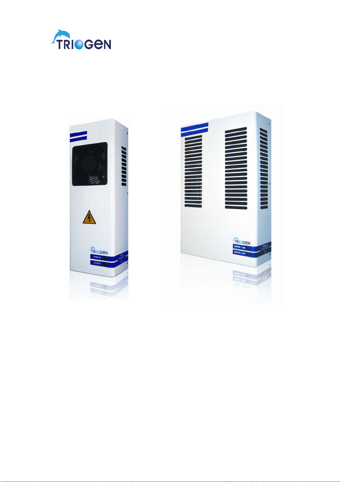
AIR DRYER
4
Triogen compact ozone generators comprise three main components – a
high voltage, high frequency power board driving a ceramic corona discharge
module which is air cooled by an integral cooling fan.
Normal atmospheric air can be used as the feed gas, or pre-dried air supplied
by a Triogen compact air dryer, either of which is drawn through the ozone
generator under vacuum which is created by a water driven venturi injector.
When the unit is switched on, an electrical corona discharge is formed within
the module by the power being supplied from the board. This reforms the
oxygen molecules (O2) present in the feed gas into ozone (O3) as the air
passes through the module.
As heat is produced by the generation of the corona discharge, it is
necessary to cool the module during operation. This is achieved by the use of
an integral cooling fan fitted within the ozone generator.
The high voltage, high frequency power board incorporates full overload and
short circuit protection. In addition a thermostat is fitted to the module which
will isolate the power in the event of a cooling fan failure causing the module
to overheat.
The ozone generator is fitted with an output control knob, located on the
underside of the unit adjacent to the pipe connectors, which electrically varies
the ozone output between 50% and 100% of the rated output of the unit.
OZONE GENERATOR

THE VACUUM INDUCTION SYSTEM
THE CONTACT / DEGASSING SYSTEM
An optional contact / degassing system is available which virtually eliminates
the air bubbles present in the ozonised water stream thereby avoiding air
entering the pool through the water inlet system.
The system comprises of a contact tank fitted with an external combined
level control and venting valve which vents the excess air and any ozone gas
present to an ozone gas destruct unit which destroys any ozone gas before
venting to the atmosphere.
The ozone gas destruct unit consists of a wall mounted container which is
filled with activated carbon through which the vented air from the degasser
unit is passed.
Any excess ozone gas present reacts with the carbon and is converted back
to oxygen before being released to the atmosphere.
It is strongly recommended that a degassing system is adopted as
entrained air entering the pool can be visually unacceptable and could
have a bleaching effect on pool liners or covers.
5
The ozone induction system is comprised of an air to water venturi injector
which is driven by a water booster pump.
The booster pump takes its supply from the filtered water return pipe to the
pool and increases the pressure of the water that then passes through the
venturi injector. The design of the injector then uses this pressure to induce a
vacuum at the side connection of the unit which is connected to the ozone
generator via a water trap assembly.
It is the creation of this vacuum that draws the air through the ozone
generator and then into the injector where the ozone gas then mixes with the
water stream.
The amount of suction created by the injector can be controlled by varying
the water flow from the booster pump by adjusting the valve fitted in the
pump discharge line. Alteration of the airflow through the generator also
controls the amount of ozone gas produced.

6
INSTALLATION OF EQUIPMENT
The installation of the equipment should only be carried out by engineers who
are trained in fitting standard pool filtration equipment.
BOOSTER PUMP & INJECTOR
The injector booster pump suction pipe should be installed as close as possible
to the main pool water return line.
The pump MUST be installed in such a manner that it has flooded suction at all
times as failure to do so will result in a premature failure of the pump seals.
The pipework should be sized to suit the suction and discharge of the pump used
and incorporate isolation valves at both take-off connections to the main pool
water return line and also between the booster pump discharge and the injector.
The injector can be mounted either in a horizontal or vertical position. It is
normally mounted directly above the booster pump discharge valve.
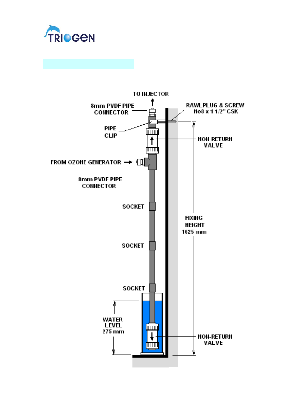
WATER TRAP ASSEMBLY
A
water trap assembly, as shown in the typical installation diagrams, MUST
always be used to ensure that water cannot pass from the injector to the ozone
generator when the water booster pump is stopped.
The water trap assembly should be wall mounted as close as possible to the
injector at a distance not exceeding 3 metres and at the height indicated.
A
fter mounting, the injector suction should be connected to the top connection o
f
the water trap assembly utilising the flexible tubing supplied. The tubing should
be clipped to the wall at 300mm centres to prevent the tubing from kinking unde
r
it’s own weight, particularly at the top connection to the water trap.
OZONE GENERATOR
The ozone generator should be wall mounted as close as possible to the wate
r
trap assembly at a distance not exceeding 3 metres and a minimum height o
f
1.65 metres above floor level.
The ozone generator MUST only be wall mounted utilising the two screw fixings
included with the unit.
When the position of the ozone generator has been ascertained, the two holes
centres should be marked and drilled in accordance with the fixing centres of the
unit. Insert the plastic rawlplugs into the drilled holes and then insert the
roundhead screws until the screw head is protruding 3mm above the surface.
The ozone generator is then hung on the screw fixings utilising the keyhole slots
on the rear of the unit.

7
OZONE GENERATOR (CONT’D)
A
fter mounting, the ozone generator air outlet should be connected to the side
connection of the water trap assembly utilising the 8mm O.D. flexible tubing
supplied with the unit and supported at 300mm centres to prevent the tubing from
kinking under it’s own weight, particularly at the side connection to the water trap.
The air flowmeter included with the ozone generator should be connected to the
air inlet of the ozoniser utilising a 25mm long piece of the 8mm O.D. flexible
tubing supplied.
When selecting a location for the ozoniser, the following instructions should be
adhered to:
The ozone generator should not be located in a position that subjects the
equipment to rain or moisture.
The ozone generator should not be located in the vicinity of any chemical storage
tanks that are likely to emit chemical fumes.
The ozone generator should not be located in the vicinity of any other equipment
that emits heat. The unit operates with fan-assisted cooling and therefore an
y
obstruction of ventilation or excessive heat will cause damage and shorten the
life of the equipment.
If the ozone generator is being installed in an unheated outdoor plantroom fo
r
use with a seasonal outdoor pool, then the unit should be removed at the end o
f
the season and stored indoors until required.
The ozone generator produces high voltage electricity, therefore never remove
the outer cover while the unit is connected to the mains power supply.
AIR DRYER
The air dryer should be wall mounted adjacent to the ozone generator at the
same height, leaving an air gap of 50mm between the units. The units should
only be mounted side by side and never above or below each other.
The air dryer MUST only be wall mounted utilising the two screw fixings included
with the unit.
When the position of the air dryer has been ascertained, the two hole centres
should be marked and drilled in accordance with the fixing centres on the unit.
Insert the plastic rawlplugs into the drilled holes and then insert the roundhead
screws until the screw head is protruding 3mm above the surface. The air drye
r
is then hung on the screw fixings utilising the keyhole slots on the rear of the unit.

8
AIR DRYER (CONT’D)
Under no circumstances should the air dryer cover be removed and the unit
screwed tightly to the wall as the wall fixing method described above is to allo
w
easy removal of the unit should it be required.
It should be noted that the air dryer utilises heat to regenerate the desiccant
material and therefore contact with the outer casing should be avoided when the
unit s in operation.
It should also be noted that the unit emits steam during its regeneration cycle and
therefore it should be located away from any other equipment which may be
affected by condensation.
The contact / degassing tank should be installed in the pipeline between the
injector and the return connection on the main pool water line ensuring that the
direction arrow on the unit is in line with the direction of flow.
On T2 and T4 systems, 1” uPVC should be used.
On T8 systems, 1 ¼” uPVC should be used.
T
he activated carbon filter pot should now be installed in a suitable position at a
maximum height of 1500mm from the top of the filter pot to floor level. The 3/8 “
uPVC pipes supplied should be assembled and then connected to the top T-
piece assembly. The non-return valve supplied as a loose item should then be
connected to the bottom of the 3/8” pipe ensuring that the flow arrow on the valve
is pointing in the direction shown on the installation diagrams.
T
he assembly should then be positioned into the bottom water trap pot and then
secured to the wall at the height shown on the installation diagrams. The bottom
non-return valve should not touch the bottom of the pot as this will restrict its
operation.
T
he activated carbon filter unit should then be charged with the materials
supplied.
First empty the contents of the gravel into the filter, followed by the activated
carbon. The materials supplied should fit exactly into the filter container. The
activated carbon will, over a period of time, degenerate through usage. When the
carbon level falls to approximately 25mm from the top of the container the
activated carbon must be topped up.
T
he level control vent valve should be connected to the filter unit using the 8mm
O.D. tubing supplied. Ensure that the tubing is firmly fixed to the wall surface,
thus avoiding any kinks developing in the system.
Fill the water trap pot to with water to 25mm from the top.
N
OTE: It is the responsibility of the user to ensure that the correct level o
f
activated carbon is maintained. Spare activated carbon can be purchased in 2k
g
p
acks from Triogen or an appointed agent.
CONTACT / DEGASSING SYSTEM

9
AIR DRYER WALL MOUNTING DETAIL
OZONE GENERATOR WALL MOUNTING DETAIL

10
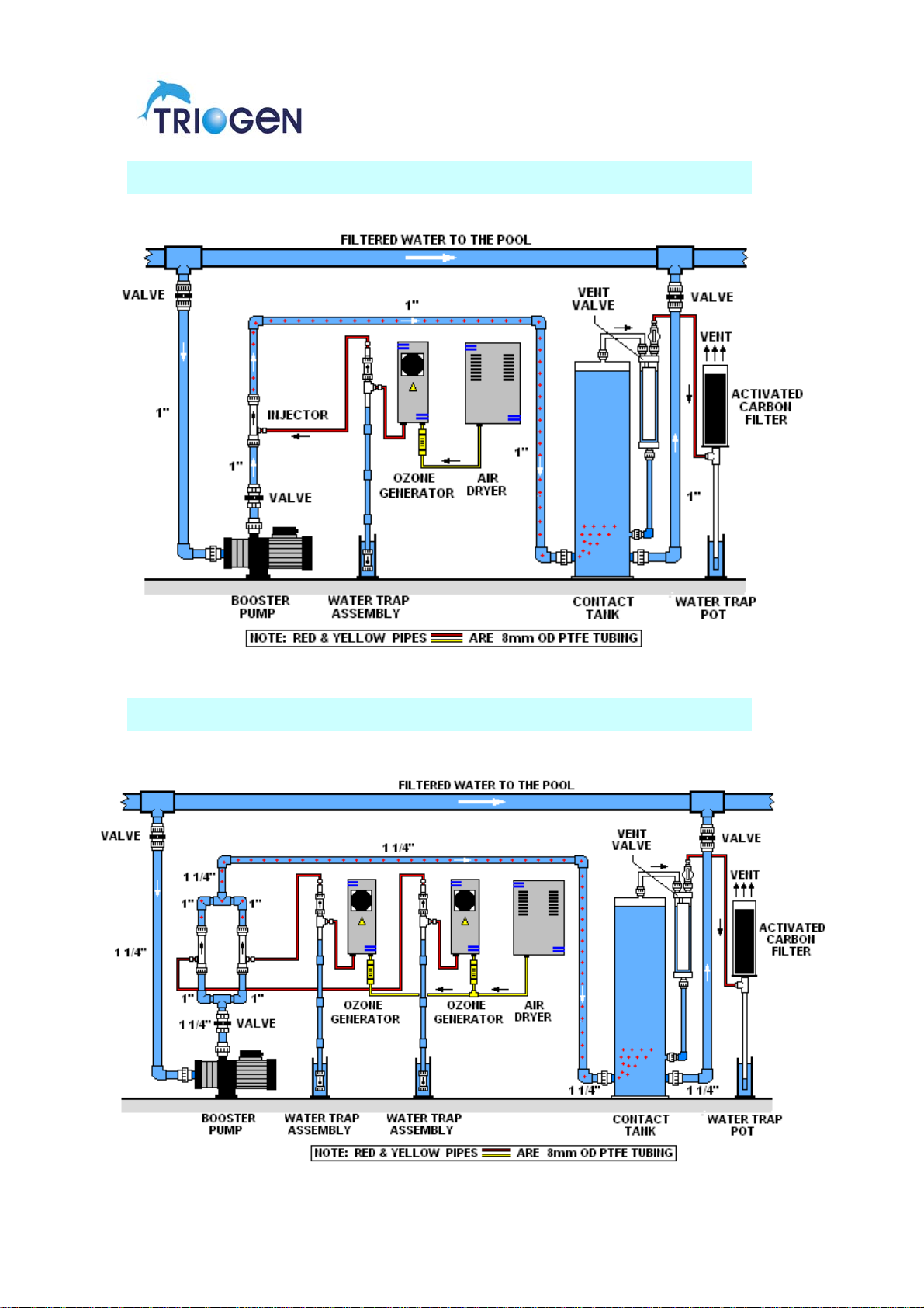
T2 INSTALLATION DIAGRAM (NO CONTACT / DEGASSER)
T2 INSTALLATION DIAGRAM WITH CONTACT / DEGASSER
11
T4 INSTALLATION DIAGRAM WITH CONTACT / DEGASSER
T8 INSTALLATION DIAGRAM WITH CONTACT / DEGASSER
12
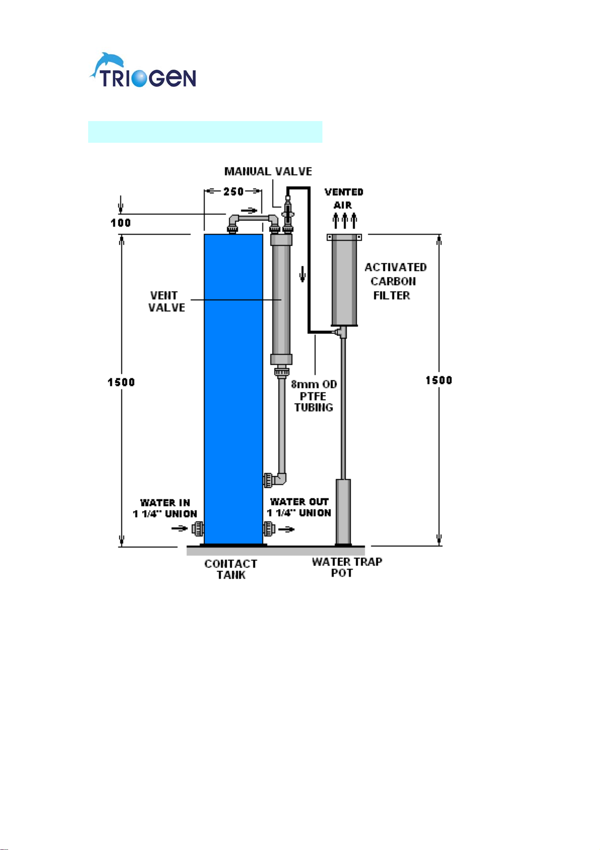
CONTACT DEGASSING SYSTEM
NOTE: THE UNIT IS SUPPLIED WITH 1 1/4” - 1” REDUCERS FOR THE WATER
CONNECTIONS TO ALLOW THE USE OF 1” PIPING
Should the plantroom be below the level of the pool, the system must run
on a 24 hour cycle, as the head of water created could cause a leak through
the vent valve and find its way into the plantroom via the waterpot. If the
plant has to be closed down for any reason, close the ½ “ compact manual
valve provided. If the plantroom is above the pool level these precautions
need not apply.
Note! The automatic level control valve is not a 100% shut off valve.
13
WATER TRAP ASSEMBLY

14
ELECTRICAL INSTALLATION
The electrical installation of the equipment should only be carried out by trained
personnel.
The ozone generator and dryer should be fitted with mains plugs in accordance with
the electrical safety instructions.
The mains socket into which the units are to be connected should be of the wall
mounted SWITCHED mains outlet type. The socket must be earthed.
The mains outlet socket can take its electrical feed from various sources, depending
on the method of control.
The injector booster pump should be electrically installed in line with manufacturers
recommendations and should be interlocked with the main circulation pump.
T2 ozone systems require a single outlet switched wall socket.
T4 ozone system requires a double outlet switched wall socket.
T8 ozone system requires a triple outlet switched wall socket.
The number of outlets above do not accommodate the injector booster pump supply
as this would normally be incorporated in the main filtration control panel or from a
separate pump starter unit.
NOTE: UNDER NO CIRCUMSTANCES SHOULD THE GENERATOR OR THE AI
R
DRYER BE HARD WIRED DIRECTLY TO A POWER SUPPLY. IF THIS IS DONE,
THE WARRANTY OF THE UNITS ARE IMMEDIATELY INVALID.
NOTE: UNDER NO CIRCUMSTANCES SHOULD THE GENERATOR OR THE AI
R
DRYER BE WIRED DIRECTLY INTO A FILTRATION CONTROL PANEL O
R
SIMILAR – THEY MUST BE WIRED AS INSTRUCTED ABOVE.
The reason for the above is to ensure that the units can be easily removed either fo
r
winter storage or servicing.
MANUAL CONTROL
If the ozone generator is to be manually controlled, the feed to the mains socket
should be directly from the main filtration control panel and interlocked with the
main circulating pump starter to ensure that the ozone system stops if the main
circulation system stops.
The switch on the mains outlet socket can then be used to stop and start the
ozone system manually as long as the circulating system is operational.
TIME CLOCK CONTROL
If the ozone system is to operate under time clock control together with othe
r
items of equipment, then the ozone system and booster pump should be fed from
the master control panel controlling all other equipment, again via a switched wall
socket into which the ozone generator (and air dryer) are plugged.

15
REDOX CONTROL
Redox control is normally only adopted for spa bath applications where accurate
dosing monitoring is required due to the high turnover rate of the spa water and
fluctuating bather loads.
The normal method adopted when ozone is to be used in conjunction with
bromine is to combine the ozone system with a commercial brominator fitted with
an electrical solenoid valve on its outlet. When the redox controller reaches the
low set point, the ozone generator, booster pump and solenoid valve on the
brominator are energised automatically and continue to run until the redo
x
controller reaches the high set point when they are switched off.
The ozone system can also be used for redox controlled applications in
conjunction with standard chlorine dosing equipment but under these conditions,
the ozone system normally runs continuously.
IN ALL CASES, THE OZONISER MUST BE PLUGGED INTO A SWITCHED
OUTLET SOCKET WHICH IS FED FROM ANY OF THE ABOVE SOURCES
AND INCORPORATES PROPER EARTHING CONNECTIONS.

16
STARTING THE OZONE SYSTEM
The start-up of the ozone system will depend largely on how the system has
been installed but the following checks should be carried out:
1. Check that the water trap pot and the degasser drain pot, if fitted, have
been filled with water to a level of 25mm from the top of the pots and
that all interconnecting tubing is correctly installed.
2. If the system is fitted with the optional degasser system, check that the
activated carbon filter pot has been charged with gravel and activated
carbon.
3. Disconnect the flexible tubing between the water trap assembly and the
ozone generator.
4. With the main circulation system running, open both system isolating
valves to the flood system, check the system for any signs of wate
r
leakage and also that the check valve assembly within the water trap
unit has stopped any backflow of water from the injector.
5. Start the booster pump to ensure that suction is achieved at the side
connection of the water trap assembly. The booster pump should be
stopped and re-started several times to ensure that the ball check valve
incorporated in the water trap assembly seals properly and stops any
water backflow from the injector. Once this has been checked, then the
suction connection to the ozone generator can be remade.
6. Switch on the ozone generator (and air dryer) and then re-start the
booster pump. Air should now be drawn through the ozone system.
7. Check the airflow through the ozone generator and set to 12 litres/min.
utilising the booster pump discharge valve to control the air flow through
the ozone generator.
8. If the system is fitted with the degasser system, check that the
automatic air release valve is venting the column properly and
maintaining a near static water level within the column.
9. Check that there is no smell of ozone from the area of the activated
carbon filter pot. If there is, turn off the ozone generator, air dryer i
f
fitted, and booster pump and carry out the checks in 1 and 2.
10. Check that the system operates correctly under time clock or redo
x
control if fitted and that if the main circulating pump stops, the ozone
system stops.
11. Check that the booster pump always maintains a flooded suction afte
r
the main circulating pump has been switched off.

17
OPERATION & MAINTENANCE
It should be noted that the noise emitted by the generator may fluctuate as the
output is varied but this will stabilise within a few minutes as the temperature o
f
the inner electrode increases or decreases in accordance with the amount o
f
power supplied to the ozone module.
The ozone system has been designed for either periodic or continuous running
with the minimum of maintenance and supervision but the following
checks should be carried out at a minimum of once per week.
Check that ozone generator and air dryer indicator lights are illuminated when
the system should be in operation.
Check the level of water in the water trap pot and top up as required to the
correct level of 25mm from the top of the pot.
Check that the correct airflow is being drawn through the ozone generator and
adjust if necessary.
Check that the injector booster pump is operating correctly.
On systems fitted with the optional degasser system, it is necessary to check the
activated carbon in the activated carbon filter pot which will degenerate
through usage. When the carbon level falls to approximately 25mm from
the top of the container the system must be topped up.
Note: It is the responsibility of the user to ensure that the correct level of
activated carbon is maintained. Spare activated carbon can be purchased
in 2kg packs from Triogen or your local distributor.
Maximum output of the generator is attained when the control knob is set to
position 10. The airflow through the generator should be maintained at the
recommended 10-12 litres/minute, irrespective of the setting used for the
variable output.
18
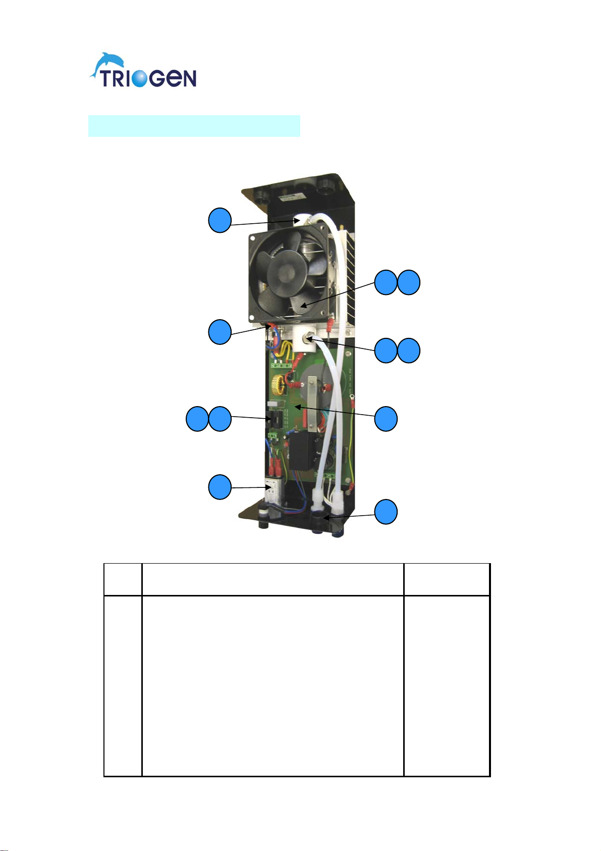
TOG B2 GENERATOR PARTS
ITEM PART BIN
No. DESCRIPTION REF.
1 TOG B2A POWERBOARD ETR0042
2 FAN 230V 120mm INPUT VERSION FAN0009
3 FAN 110V 120mm INPUT VERSION FAN0001
4 OZONE MODULE END CAP MPP0089
5 MALE ADAPTOR UNION 8mm - 1/8" ST.ST. MPM0072
6 UNION SEAL RING 1/8" FES0034
7 PANEL MOUNTED UNION 8mm x 8mm PVDF PPF0209
8 MODULE THERMOSTAT 70oC EMC0181
9 MAINS POWER FILTER SOCKET EMC0104
10 FUSE 5 x 20 1 AMP TYPE T 230V ECA0119
11 FUSE 5 x 20 2 AMP TYPE T 110V ECA0106
1
2 3
4
5 6
7
8
9
10 11
This manual suits for next models
4
Table of contents


