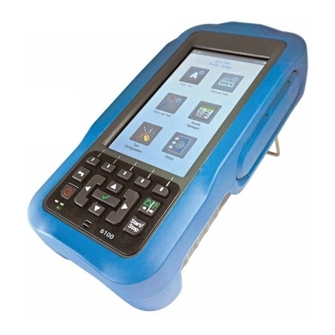
Triol TM01 User manual


2
Dear Customer!
Thank you for purchasing Triol TM01 Downhole Measuring System, the key to your
successful oil production strategy.
We are sure that our Downhole Measuring System technologies will allow you to
advance and maximize your production.
TM01 is complete with the following manuals:
Operation Manual Surface Equipment
Operation Manual TM01-10/11/18/20
Operation Manual TM01-05/15/25/28
Up-to-date technical documentation for TM01 can be downloaded here
https://triolcorp.eu/documents/ or using the QR-code.
Operation of the Triol Surface Equipment must be conducted by personnel
specially trained and authorized by the operator.
The manufacturer reserves the right to make circuital and design changes that are
not reflected in the operational documentation and do not impair the technical
specifications of the device.

3
Copyright © Triol Corporation Ltd. 1993-2020 All rights reserved.
No part of this publication may be reproduced or copied without prior
written permission from Triol Corporation Ltd.
All products and company names mentioned in this manual are trademarks
or registered trademarks of their respective holders.
The information contained herein is subject to change without prior notice
for improvement.

4
CONTENTS
List of abbreviation and warning indicators......................................................................................5
Triol blocks compatibility..................................................................................................................6
Safety requirements.........................................................................................................................7
Description.......................................................................................................................................9
Surface Card description..............................................................................................................9
Surface Board description...........................................................................................................13
Surface Panel description...........................................................................................................16
High-Voltage Choke IP56 description.........................................................................................19
High-Voltage Choke Flexible description....................................................................................20
Connection and configuration ........................................................................................................21
Triol Surface Card.......................................................................................................................21
Connection..............................................................................................................................21
Surface Card menu description...............................................................................................23
Starting up a Surface Card......................................................................................................26
Setting event log recording......................................................................................................26
Setting Wi-Fi............................................................................................................................27
Triol Surface Board.....................................................................................................................29
Connection..............................................................................................................................29
Surface Board testing..............................................................................................................30
Starting up a Surface Board....................................................................................................33
Data channel to the ACS (SCADA) .........................................................................................33
Triol Surface Panel.....................................................................................................................36
Connection..............................................................................................................................36
Surface panel testing...............................................................................................................37
Starting up a Surface Panel.....................................................................................................38
Setting event log recording......................................................................................................39
Setting up analog outputs (if included) ....................................................................................40
Configuring digital outputs (if included)....................................................................................40
Triol High-Voltage Choke............................................................................................................41
Connection..............................................................................................................................41
Installation of surface equipment on shelving..........................................................................43
Troubleshooting.............................................................................................................................46
Diagnostics flow charts...............................................................................................................46
Fuse replacement instructions for High-Voltage Choke..............................................................55
Storage ..........................................................................................................................................58
Periodical Maintenance..................................................................................................................58
APPENDIX A .................................................................................................................................59
APPENDIX B .................................................................................................................................63
APPENDIX C.................................................................................................................................68
APPENDIX D.................................................................................................................................71
APPENDIX E .................................................................................................................................80
APPENDIX F..................................................................................................................................83
APPENDIX G.................................................................................................................................84
APPENDIX H.................................................................................................................................85

5
List of abbreviation and warning indicators
Abbreviation:
TM01 –Downhole Measuring System
SB –Surface Board
SP –Surface Panel
SC –Surface Card
TM01-XXi –Downhole Intake Sensor
TM01-XXd –Downhole Discharge Sensor
HVC –High-Voltage Choke
ESM –Electric Submersible Motor
ESP –Electric Submersible Pump
OM –Operation Manual
0-SUT –Step-up Transformer zero point
GND –Ground
VSD –Variable Speed Drive
ACS –Automatic Control Station.
Indicators:
- Information to be considered.
- Attention! Caution or danger warnings.

6
Triol blocks compatibility
Surface unit
Downhole unit
Add. equipment
Board
Triol Surface Board ST
TM01-05
When connecting the
secondary winding of
the "Delta" transformer,
Triol High-Voltage
Choke IP56 or Triol
High-Voltage Choke
Flexible (without filter)
is used
TM01-09
TM01-10
TM01-15
TM01-20
TM01-25
TM01-28
Triol Surface Board LF
TM01-11
Triol Surface Board DG
TM01-12
Surface
Triol Surface Panel
TM01-05
TM01-09
TM01-10
TM01-15
TM01-20
TM01-25
TM01-28
Card
Triol Surface Card
TM01-05
Triol High-Voltage
Choke Flexible or Triol
TM01- Filter
TM01-09
TM01-10
TM01-15
TM01-20
TM01-25
TM01-28

7
When the supply voltage is applied to the VSD and the circuit breaker of the «0-
SUT» Downhole Measuring System of the VSD is on, a voltage of 100V or 200V
(SB DG) is supplied. Therefore, you must comply with the relevant electrical safety
requirements when installing the pumping unit.
ATTENTION! Filter capacitors retain life-threatening charge. Before working with
the downhole measuring system, make sure that capacitors are de-energized.
Safety requirements
The safety requirements for the control, operation, maintenance and repair of the system must
comply with the Occupational Health and Safety Management Systems (BS OHSAS 18001:2007),
Safety Rules for Operation of Customers’ Electrical Installations, Rules for Safety in the Oil and
Gas Industry, and Inter-industry Rules on Labor Safety.
All actions for installation, assembly, dismantling, operation, and Downhole Measuring System
maintenance must be performed in accordance with applicable local and electrical codes.
Inappropriate installation and operation of the Downhole Measuring System may result in personal
injury or equipment damage. When installing, maintaining, and repairing, it is important to monitor
lack of voltage at the input and output terminals and wires.
Before starting work with the Downhole Measuring System, employees must:
·be specially trained and examined in labor protection issues
·attend a preliminary medical examination (when hired for work) and periodic health
examinations (during the entire labor activity)
·have an electrical safety qualification.
When connecting to the power supply line, special attention must be paid to ensuring reliable
grounding of board/panel casing.
Grounding resistance must meet the local and national requirements.
When performing any work with the Downhole Measuring System, security measures
must be taken:
·disconnect power to the VSD
·disconnect power to the SB, SC, and SP
Figure 1 - Surface Panel power switch
ATTENTION! Installation of telemetry must be carried out when the ESM and
VSD power supplies are completely switched off.

8
Safety recommendation
The Downhole Measuring System must be installed, adjusted, and serviced by qualified
electrical maintenance personnel. Improper installation or operation may cause injury to personnel
or damage to equipment. The Downhole Measuring System must be installed and grounded in
accordance with local and national electrical codes. There is a high level of voltage in the drive’s
cabinet. Extreme care must be taken to ensure all power sources are disconnected before
starting installation, maintenance, and repair jobs. Once repairs are completed, the Downhole
Measuring System connections must be re-established.
Personal Protective Equipment (PPE)
The basic personal protective equipment (PPE) required for field service includes, but is not
limited to, steel toe shoes, safety glasses and a hard hat. If electrical configuration or
maintenance is performed on potentially energized circuits, personal protective equipment is
required to minimize the danger of electrical shock, arc flash and/or arc blast. The level of PPE
required can vary based upon the electrical energy available at the installation site. If any doubt
exists, consult and employ the recommendations published in the National Fire Protection Code,
NFPA-70E. Always be aware of, and conform to, the applicable local fire and electrical safety
regulations.
Safety Procedures
Work inside the cabinets must be performed with the power off. Isolate energy source(s)
and use proper Lock Out/Tag Out (LOTO) procedures and personal protective equipment (PPE)
to ensure personnel safety. The panel/board also contains stored sources of energy in the form of
capacitors. Allow sufficient time after power is removed for those capacitors to discharge to a
safe level below 50VDC.

9
Description
Surface Card description
Surface Card (IP20 enclosure) is designed for inside the VSD installation.
Figure 2 –Surface Card
Surface Card specification with all parameters, operating conditions, and overall dimensions:
Table 1 –Surface Card specification
Input/Output parameters
Rated voltage
24VDC +10, -20%
Power consumption, not more than
50W
Duration mode
Long
Operating voltage in the communication circuit
with submersible unit (if the insulation of Step-up
–cable ESM system is in operation condition)
100V
Design and control connections
Enclosure, not lower than
IP20
Display
LCD 3.5”, 320x240
Wired communication interface
RS-485, RS-232, USB com
Wireless communication port
Wi-Fi
Environmental conditions
Ambient temperature
from -20°С (-4°F) to +85°С (185°F)
Relative air humidity at + 25°C, without
condensation
100%
Altitude, not more than
3281ft (1000m)
Overall dimensions and weight
Overall dimensions, not more than
150mm (5.90in) x 120mm (4.70in) х
70mm (2.75 in)
Weight, not more than
0.7kg (1.54lbs)

10
Description of the elements of the Surface Card:
Power –Surface Card powered
Sensor –communication available / no communication with downhole sensor
R ins –insulation resistance / current leakmeasurement
Alarm –alarm triggering
Display–display of current parameters
USB com –service port
USB host –reading log file
Keyboard –navigate the Surface Cardmenu
There are indicators and various signs on the Surface Card, the description of which are
given below.
Figure 3 –Surface Card (front view)

11
Description of the elements of the block Surface Card:
1. Interface port (RS-232, RS-485)
2. Dout port (Dout1, Dout2)
3. Supply port (24VDC)
4. Output port (supply downhole sensor)
Figure 4 –Surface Card (bottom view)
To switch on Surface Card, it is necessary to supply power to the unit. Table 2 shows
the possible status indications on the Surface Card.

12
Table 2 - Description of LED indicators on the Surface Card
LED
Status
Description
Power
ON
24VDC power applied
OFF
no 24 VDC power applied
Sensor
ON
(green)
there is no communication failure with downhole
sensor
ON
(red)
there is communication failure with downhole sensor
R ins
ON
insulation resistance/current leak measurements
OFF
data transmission from downhole sensor
Alarm
ON
Digital output has triggered. The value of one of
the set parameters has gone beyond the minimum
or maximum.
OFF
Digital outputs are disabled. Parameter values did not
go beyond the minimum and maximum.

13
Surface Board description
The Triol Surface Board ST, LF, DG (IP20 enclosure) is designed for inside the VSD
installation. The Surface Board offers RS-485 and RS-232 Modbus ports as standard.
Figure 5 - Surface Board
Surface Board specification with all parameters, operating conditions, and overall
dimensions:
Table 3 –Surface Board ST, LF, DG specification
Input/Output parameters
Rated voltage*
220V (±20%), 110V (±10%)
Frequency
50/60Hz (±2%)
Power consumption, not more than**
40W
Duration mode
Long
Operating voltage in the communication circuit
with submersible unit (if the insulation of Step-
up –cable ESM system is in operation
condition)***
100V
Design and control connections
Enclosure, not lower than
IP20
Display
None
Physical interface
RS-485/232 Modbus RTU
Environmental conditions
Ambient temperature
from -60°С (-76°F) to +85°С (185°F)
Relative air humidity at +25°C, without
condensation
100%
Altitude, not more than
3281ft (1000m)
Overall dimensions and weight
Overall dimensions, not more than
216mm (8.5in) x 240mm (9.45in) х
142mm (5.6in)
Weight****, not more than
4kg (8.8lbs)
*
Surface Board DG rated voltage is 220V (±20%)
** Surface Board DG power consumption is not more than 100W
*** Operating voltage in the communication circuit is 200V
**** Surface Board DG weight is not more than 6kg (13.23lbs)

14
Description of the elements of the Surface Board:
Heating –heating work
R ins. –insulation resistancemeasurement
Sensor –SB works with downhole sensor
Power –SB powered
GND –ground
0-SUT –cable for connecting intake sensor through the transformer wye point
110/220V–input voltage Surface Board ~ 110 ... 220V AC (for SB DG –220V)
RS-485 –RS-485 communication interface
RS-232, RS-485 –RS-232 communication interface and RS-485 interface
contacts are duplicated
There are indicators and various signs on the Surface Board, the description of which are
given below.
Figure 6 –Surface Board
To switch on the SB, it is necessary to supply power to the unit. Table 4 shows the
possible status indications on the SB.

15
Table 4 - Description of LED indicators on the Surface Board
LED
Status
Description
R ins.
ON
When power is applied to the SB, all LEDs
are turned on for 5 seconds. Checking the health of
LEDs
Sensor
ON
Power
ON
R ins.
OFF
The SB is not powered or the power
supply in the SB is faulty
Sensor
OFF
Power
OFF
R ins.
ON
The SB measures insulation resistance
Sensor
OFF
Power
ON
R ins.
OFF
The SB powers the downhole sensor
The downhole sensor measures and transfers data to
the SB
Sensor
ON
Power
ON
R ins.
Blink
Insulation resistance less than 10kΩ. A delay of 20
seconds to the next measurement without powering
the downhole sensor
Sensor
OFF
Power
ON
R ins.
OFF
Processing a reset command for the downhole
sensor.
The downhole sensor constant power mode is on, or
in the included Rins test mode
Sensor
Blink
Power
ON
The Surface Board transmits data via RS-232 and RS-485 interfaces. The SB is a slave device
that responds to master requests, for example, the board responds to requests from the ACS
(SCADA).
Interface settings and register map are in Appendix B of Modbus map.

16
Surface Panel description
The Triol Surface Panel (IP56 enclosure) shows information on the display for operators to
read and process data in real time relating to the fluid parameters and parameters of the submersible
equipment. The SP offers an RS-485 Modbus port as standard. Digital and analog I/O are optional.
Figure 7 - Surface Panel
Surface Panel specification with all parameters, operating conditions, and overall
dimensions:
Table 5 –Surface Panel specification
Input / Output parameters
Rated voltage
220V (±20%), 110V (±10%)
Frequency
50/60Hz (±2%)
Power consumption, not more than
300W
Duration mode
Long
Operating voltage in the circuit with
submersible unit (if the insulation of Step-up is
an ESM cable)
100V
Design and control connections
Enclosure, not lower than
IP56
Display
LCD 20x4 Symbols
Physical interface
RS-485/232 Modbus RTU
Environmental conditions
Ambient temperature
from -40°С (-40°F) to +75°С
(167°F)
Relative air humidity at +25°C,
without condensation
100%
Altitude, not higher than
3281ft (1000m)
Overall dimensions and weight
Overall dimensions, not more than
230mm (9.05in) x 460mm
(18.11in) х 505mm (19.88in)
Weight, not more than
30kg (66.1lbs)

17
There are indicators and various signs on the SP, the description of which are given below.
The layout of the SP controls is shown in figures 8 and 9.
Figure 8 –Surface Panel (front view)

18
Description of the elements of the Surface Panel:
1. USB –connector for external flash media
2. RS-485 –DB9 connector for RS-485 communication
3. Heating –SP heating works
4. R ins. –insulation resistance measurement
5. Sensor –SP works with downhole sensor
6. Power –SP is powered
7. Power ON/OFF –circuit breaker QF1
8. Control buttons –scroll through menus and adjust settings
9. LCD –screen for displaying information and setting parameters
10.Operation –connection established, there is no error
11.Error –there is an error
12.Alarm –there is no connection to TM01
13.GND –grounding
14.Network –power connection
15.0-SUT –connection to the transformer wye point
16.RS-232/ RS-485 –Phoenix terminal (XT3) for RS-485 and RS-232
communication
17.Extreme inclusion of a Surface Panel
Figure 9 –Surface Panel (bottom view)
To switch on the Surface Panel, it is necessary to supply power of 110-220V and turn on
the QF1 circuit breaker according to the wiring diagram.
The Surface Panel can exchange data with the upper level via an RS-485 interface using
one of the following protocols: Triol, TriolAK, and Transfer. Description of the protocols are
presented in Appendix C.

19
High-Voltage Choke IP56 description
Triol High-Voltage Choke IP56 provides a zero “wye” point when the transformer is connected
in «delta» mode.
Figure 10 High-Voltage Choke
High-Voltage Choke specification with all parameters, operating conditions, and overall
dimensions:
Table 6 –High-Voltage Choke specification
Input / Output parameters
Maximum voltage of power circuits
5000V
High-Voltage Choke current saturation, not less
than
70mA
Maximum choke power circuit current
160mA
Phase inductance, not less than
140H
Duration mode
Long
Design and control connections
Enclosure, not lower than
IP56
Number of safety interlocks
3
Environmental conditions
Ambient temperature
from -20°С (-4°F) to +60°С
(140°F)
Relative air humidity at +25°C,
without condensation
100%
Altitude, not higher than
3281ft (1000m)
Overall dimensions and weight
Overall dimensions, not more than
229mm (9.02in) x 460mm
(18.11in) х 501.5mm (19.7in)
Weight, not more than
35kg (77.1lbs)

20
High-Voltage Choke Flexible description
Triol High-Voltage Choke Flexible (IP56, IP65, IP00) provides a zero “wye” point when the
transformer is connected in «delta» mode.
Figure 11 High-Voltage Choke Flexible
High-Voltage Choke specification with all parameters, operating conditions, and overall
dimensions:
Table 7 –High-Voltage Choke Flexible specification
Input / Output parameters
Maximum voltage of power circuits
5000V
High-Voltage Choke current saturation, not less
than
70mA
Maximum choke power circuit current
160mA
Phase inductance, not less than
140H
Duration mode
Long
Design and control connections
Enclosure, not lower than
IP56/IP65
Number of safety interlocks
3
Environmental conditions
Ambient temperature
from -20°С (-4°F) to +60°С (140°F)
Relative air humidity at +25°C,
without condensation
100%
Altitude, not higher than
3281ft (1000m)
Overall dimensions and weight
Overall dimensions IP56, not more than
Overall dimensions IP65, not more than
327mm (12.8in) x 375mm
(14.8in) х 156mm (6.1in)
327mm (12.8in) x 375mm
(14.8in) х 156mm (6.1in)
Weight IP56, not more than
Weight IP65, not more than
24kg (52.9lbs)
22kg (48.5lbs)
Table of contents
Popular Measuring Instrument manuals by other brands
Winland Electronics
Winland Electronics TempAlert MTA-1 quick start guide
ABB
ABB C11 user manual

GW Instek
GW Instek GLA-1016 user manual
Union Instruments
Union Instruments INCA4003 Translation of the original operating instructions
KATA
KATA DGM-1500 Turva manual

Vanguard Instruments
Vanguard Instruments Auto-Ohm 10 user manual
