ONE YEAR LIMITED WARRANTY
Winland Electronics, Inc. warrants that each product of its manufacture
is free from defects in material and factory workmanship, when
properly installed and operated under normal conditions according
to the manufacturer’s instructions. Manufacturer’s obligation under
this warranty is limited to correcting, without charge, at its factory
any part of parts thereof which shall be returned to the factory, by
the original retail purchaser, transportation charges prepaid, within
one year after purchase and which upon examination shall disclose
to the manufacturer’s satisfaction to have been originally defective.
Correction of such defects by repair to, or supplying of replacements
for defective parts shall constitute fulfillment of all obligations to
purchaser. Repair service performed by the manufacturer after one
year from date of purchase will be for a reasonable service charge.
This warranty shall not apply to any of the manufacturer’s products
which have been subject to misuse, negligence or accident of which
shall have been repaired or altered outside of the manufacturer’s
factory. Manufacturer shall not be liable for loss, damage, or expense
directly or indirectly from the use of its product or from any other
cause. THIS WARRANTY IS IN LIEU OF ALL OTHER WARRANTIES,
EXPRESSED OR IMPLIED. WARRANTIES OF MERCHANTABILITY AND
FITNESS FOR PARTICULAR PURPOSE ARE EXCLUDED, AS ARE ALL
OTHER REPRESENTATIONS TO THE USER-PURCHASER, AND ALL
OTHER OBLIGATIONS OR LIABILITIES, INCLUDING LIABILITY FOR
INCIDENTAL AND CONSEQUENTIAL DAMAGES, ON THE PART OF
THE MANUFACTURER OR THE SELLER. No person, agent or dealer is
authorized to give any warranties on behalf of the manufacturer nor
to assume for the manufacturer any other liability in connection with
any of its products.
WEEE Product Recovery/Recycling for EU Customers
In an effort to improve waste management in the European Union,
the European Union has enacted directive 2002/96/EC on Waste
Electrical and Electronic Equipment (WEEE Directive). According to the
WEEE Directive, Winland Electronics must take back waste electrical
or electronic equipment covered under the WEEE Directive, at its cost,
for all product it puts on the market after July 1, 2006. The Return
Process: Contact Winland via our web site at www.winland.com and go
to the WEEE link on the home page. To request additional information
regarding Winland’s RoHS and WEEE compliance initiative and how it
MTA-1 Certification Info
Statement of Compliance
Winland Electronics, Inc. hereby declares this device is in compliance
with all the applicable Directives 2002/95/EC, 2002/96/EC.
This device is considered a passive EM device and is thereby
excluded from the scope of the EMC directive (89/336/EEC).
Symbols on the Product or Manual Labeling
For product disposal, ensure the following:
• Do not dispose of this product as unsorted municipal
waste.
• Collect this product separately.
• Use collection and return systems available to you.
WEEE Waste Electrical and Electronic Equipment
RoHS Restriction of Hazardous Substances
Operation and Testing Procedures
For proper operation, the MTA-1 must be located in an area
where the temperature range is within +30˚ to +100˚ F (+1˚ to
+38˚ C). To manually activate the MTA-1 for testing, loosen the
locknut of one limit post and slide it toward the temperature
indicator until it makes contact and temporarily tighten the
locknut nut. If installed correctly, this test procedure should
activate the warning device to which the MTA-1 is connected.
After testing, loosen the locknut, return the limit arm to it
original set point and tighten the locknut. The same test
procedure should also be repeated with the second limit arm
to verify proper operation.
TA-1
Single output temperature monitoring
• No power required to operate
• -30 to 130°F sensing range
• N.O. dry contacts
• Not for use in coolers and freezers
TA-2HL
Dual output temperature monitoring
• No power required to operate
• -30 to 130°F sensing range
• N.O. dry contacts
• Not for use in coolers and freezers
TA-40
Single output temperature monitoring
• No power required to operate
• N.C. above 40°F
• Not for use in coolers and freezers
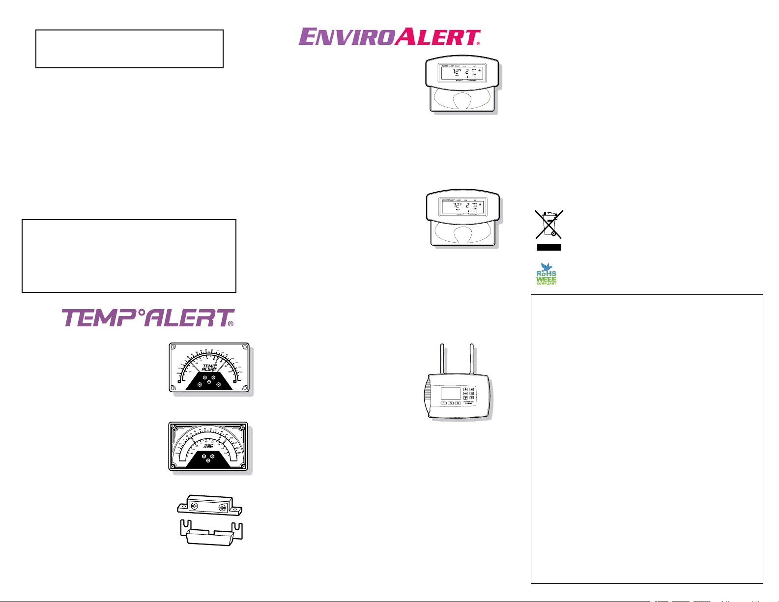
EnviroAlert® EA200
Dual Zone Wireless Electronic Monitor:
Temperature, Humidity, Water
EA200-12 (12VDC)
EA200-24 (24VDC)
Has one built-in ambient temp sensor
Connect up to 1 hard wired sensor
Eight event alarm history
Defrost delay time up to 120 minutes
Tamper proof lock setting
Temp and humidity high and low set points
EnviroAlert® EA400
Four Zone Wireless Electronic Monitor:
Temperature, Humidity, Water
EA400-12 (12VDC)
EA400-24 (24VDC)
Connect up to 4 hard wired sensors
Eight event alarm history
Defrost delay time up to 120 minutes
Tamper proof lock setting
Temp and humidity high and low set points
EnviroAlert® EA800
Eight Zone Wireless Electronic Monitor:
Temperature, Humidity, Water, Closed Contact, 4-20mA
EA800 (11-26 VDC @ ≤500mA)
Connect up to 4 wireless
and up to 4 hard wired sensors
Password protected programming lock
Intuitive user interface
Automatic data logging
(transferable via USB stick)
Sensor data
Event and alarm history
Collection frequency from 30 sec to 120 min
8 zone specific relays with 1 auxiliary relay
On-board piezo buzzer
Accommodates 4-20mA sensors (pressure, flow, CO2, etc)
Individual hard wire probe temp sensor calibration via USB
Defrost delay time up to 120 minutes
Temp and humidity high and low set points
Product CD includes (also available on-line at EA800.net):
Owners Manual
Quick Start Guide
Wireless Sensor Placement Guide
Data Log Template
Technical Instructions
IMPORTANT NOTE:
To insure proper operation, test the unit weekly.
IMPORTANT:
Do not use the MTA-1 in a cooler or freezer. Frost
buildup and moisture can cause the unit to
malfunction. For cooler & freezer applications, use one
of the EnviroAlert® products with a remote probe.


