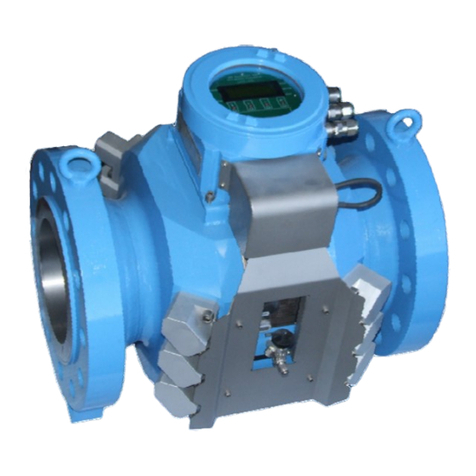
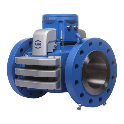
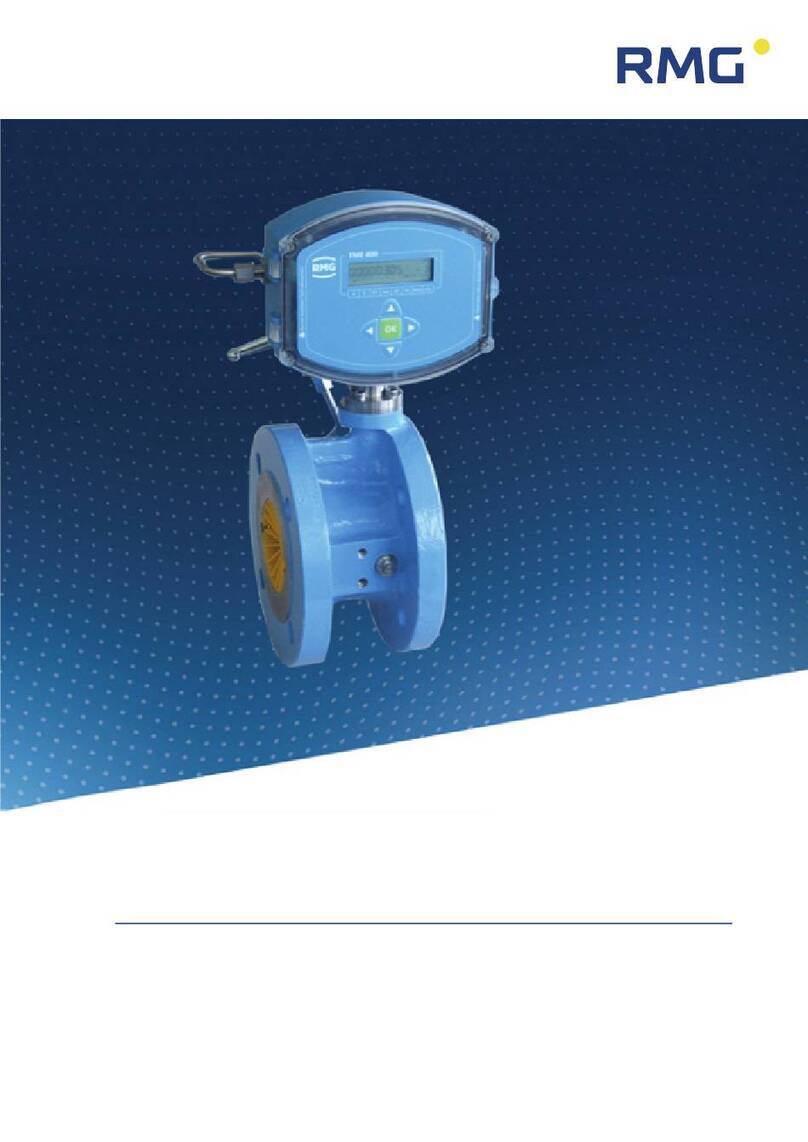
RMG USM GT400 User manual

Operating Manual
Ultrasonic Flowmeter USM GT400
Issued:
07.05.2021
Version:
10
Firmware:
1.5

Contact
Manual USM GT400 · EN10 · May 2021
Manufacturer
Our customer service is available for technical queries:
Address
RMG Messtechnik GmbH
Otto-Hahn-Straße 5
D-35510 Butzbach
Telephone Switchboard
+49 6033 897 –0
Telephone Service
+49 6033 897 –0
Telephone Spare Parts
+49 6033 897 –173
Fax
+49 6033 897 –130
E-Mail
Original Document
The Ultrasonic Flowmeter USM GT400 OPERATING
INSTRUCTION 07.05.2021 is the original document.
This document may serve as a reference for translations into
other languages. Please use in case of any uncertainties the
German version as main reference.
Note
Unfortunately, paper is not updated automatically, whereas
technical development continuously advances. Therefore, we
reserve the right to make technical changes regarding the rep-
resentations and specifications of these operating instructions.
The latest version of this manual (and other devices) can be
downloaded at your convenience from our Internet homepage:
www.rmg.com
Date created
1/31/2014
…
4th revision date
02/12/2018
5th revision date
09/4/2018
6th revision date
11/18/2018
7th revision date
12/14/2019
8th revision date
02/19/2021
9th revision date
05/07/2021
Document version
and language
Document version
Ultrasonic Flowmeter USM GT400
manual de May 7th 2021
Language
EN

Contents
Manual USM GT400 · EN10 · May 2021
I
Content
1ABOUT THIS MANUAL......................................................................... 1
1.1 Objective of the manual.......................................................................................1
1.2 Specialized knowledge required .......................................................................2
1.2.1 Specialized knowledge required..........................................................................2
1.2.2 Abbreviations.......................................................................................................3
1.2.3 Layout of instructions ..........................................................................................4
1.2.4 Working with the device ......................................................................................5
1.2.5 Risk assessment and minimization...................................................................11
1.2.6 Validity of the manual........................................................................................13
1.2.7Transport...........................................................................................................14
1.2.8 Scope of delivery...............................................................................................16
1.2.9 Disposal of packaging material .........................................................................16
1.2.10 Storage..............................................................................................................16
1.3 Explosion-proof design.....................................................................................17
1.3.1 General information...........................................................................................17
1.4 Inspection and maintenance work..................................................................18
1.4.1 General information...........................................................................................18
2QUICK GUIDE....................................................................................... 20
2.1 Mechanical connection......................................................................................21
2.1.1 Connection flanges............................................................................................21
2.1.2 Inlet / outlet piping .............................................................................................21
2.1.3 Joining pressure connections............................................................................21
2.2 Electrical connection .........................................................................................22
2.3 Start up..................................................................................................................22
2.4 Earthing.................................................................................................................23
2.5 Parameter setting................................................................................................24
3DEVICE OVERVIEW............................................................................ 25
3.1 Main components................................................................................................25
3.2 Ultrasonic electronics........................................................................................27
3.3 Arrangement of the ultrasonic transducers .................................................31
4FUNCTIONAL PRINCIPLE –ULTRASONIC-FLOW
MEASUREMENT.................................................................................. 32

Contents
Manual USM GT400 · EN10 · May 2021
II
4.1 General description............................................................................................33
4.2 Correction of the base line...............................................................................37
4.2.1 Base line correction via polynomial................................................................... 38
4.2.2 Correction via a piecewise linearization............................................................ 39
4.3 Diagnostic function Speed of Sound............................................................. 40
4.3.1 Standard method of SoS calculation................................................................. 40
4.3.2 SoS calculation via gas components ................................................................ 40
4.3.3 Extended SoS calculation................................................................................. 41
4.4 Import of gas composition data...................................................................... 42
4.4.1 Option 4: Data input on fixed defaults............................................................... 43
4.4.2 Data input on fixed defaults for air .................................................................... 43
4.4.3 Data input via RMGBus .................................................................................... 45
4.4.4 Data via Modbus (USM GT400 is SLAVE) ....................................................... 46
4.4.5 Import of data via Modbus (USM GT400 is Master).......................................... 47
4.5 Batch mode..........................................................................................................52
4.6 Signal damping ................................................................................................... 52
5SAFETY.................................................................................................. 53
5.1 Intended use ........................................................................................................54
5.2 Layout of instructions .......................................................................................55
5.3 Qualification of the personnel......................................................................... 56
5.4 Safety instructions............................................................................................. 57
5.4.1 Hazards during transporting.............................................................................. 58
5.4.2 Hazards during installation................................................................................ 58
5.4.3 Hazards during start up..................................................................................... 60
5.4.4Hazards during cleaning ................................................................................... 61
5.4.5 Hazards during maintenance and repairs......................................................... 61
5.4.6 Hazards during operation.................................................................................. 62
5.4.7 Hazards for operation in potentially explosive environments............................ 63
5.5 Responsibilities of the operator......................................................................64
6TRANSPORT AND STORAGE.......................................................... 65
6.1 Transport.............................................................................................................. 66
6.1.1 Scope of supply ................................................................................................ 66
6.1.2 Transporting the device .................................................................................... 67
6.1.3Unpacking the device........................................................................................ 67
6.1.4 Disposal of packaging material......................................................................... 70
6.1.5 Prior to installation ............................................................................................ 70
6.1.6 Removing the transporting locks....................................................................... 71

Contents
Manual USM GT400 · EN10 · May 2021
III
6.2 Packing the device for transportation............................................................73
6.3 Storage ..................................................................................................................79
6.3.1 Packing the device for storage..........................................................................79
6.3.2 Checking the device after storage.....................................................................80
7CONSTRUCTION AND PLANNING.................................................. 81
7.1 Connection flanges.............................................................................................81
7.2 Seals.......................................................................................................................82
7.2.1 Flat seal.............................................................................................................83
7.2.2 Grooved gaskets...............................................................................................84
7.2.3 Spiral seals........................................................................................................85
7.3 Screws...................................................................................................................87
7.4 Installation possibilities ....................................................................................88
7.4.1 Dependency on the gas flow direction ..............................................................88
7.4.2 Two devices series connected (Face to Face)..................................................91
7.5 Flow computer.....................................................................................................93
8INSTALLATION.................................................................................... 95
8.1 Assembly work preparations ...........................................................................96
8.2 Installation of the device...................................................................................99
8.2.1 Mounting the inlet and outlet piping...................................................................99
8.2.2 Installation of the connection box....................................................................101
8.3 Connecting the device electrically............................................................... 103
8.3.1 Connecting the power supply..........................................................................108
8.3.2 Digital interfaces of USM-GT400.....................................................................108
8.3.3 Connecting the computer for RMGViewUSM.....................................................110
8.3.4 Connecting the flow computer.........................................................................110
8.3.5 Connection of external DSfG-Device-F via Modbus........................................113
8.3.6 Interface converter ..........................................................................................124
8.3.7 Connecting the device to earth........................................................................126
8.4 Installing the pressure connection.............................................................. 128
8.5 Outdoor installation......................................................................................... 130
9START UP ........................................................................................... 132
9.1 Comparing meter parameters....................................................................... 132
9.2 Checking functions of the USM.................................................................... 132
9.3 Reading out speed of sound......................................................................... 133

Contents
Manual USM GT400 · EN10 · May 2021
IV
10 OPERATION........................................................................................ 134
10.1 Measuring values and parameters............................................................135
10.1.1 Input protection for parameters....................................................................... 135
10.1.2 Parameter and measuring values with variable units ..................................... 135
10.1.3 Calibration and Service Switch ....................................................................... 136
10.1.4 Interfaces to converters and controllers.......................................................... 136
10.1.5 Interface for service and parameterization...................................................... 137
10.1.6 Adaptation of the DZU protocol to ERZ 2400 ................................................. 138
10.2 Calling up and changing the parameters via the ultrasonic electronics
139
10.2.1 Calling up the value of a parameter................................................................ 140
10.2.2 Entering data................................................................................................... 141
10.2.3 Changing the parameters of protection E and S............................................. 144
10.3 Parameterize the USM interface.................................................................149
10.3.1 Interface 0....................................................................................................... 149
10.3.2 Interface 1....................................................................................................... 150
10.3.3 Interface 2....................................................................................................... 150
10.4 Modbus communication in detail ..............................................................161
10.4.1 Codes supported............................................................................................. 161
10.4.2 Data types....................................................................................................... 161
10.5 Configuration of the current output..........................................................163
10.6 List of the measurement values and parameters.................................163
11 MAINTENANCE.................................................................................. 164
11.1 Maintenance schedule .................................................................................165
11.2 Checking the device for leaks....................................................................165
11.3 Checking the device for any signs of damage.......................................166
11.4 Changing the battery....................................................................................166
11.5 Changing the transducer.............................................................................166
11.6 Changing the ultrasonic electronics.........................................................167
11.7 Cleaning the device ......................................................................................167
11.8 Check the official seal..................................................................................168
11.9 Decommissioning and disposal ................................................................168
12 ALARM AND WARNING MESSAGES ........................................... 170
12.1 Alarm messages............................................................................................171
12.2 Warning messages........................................................................................172

Contents
Manual USM GT400 · EN10 · May 2021
V
12.3 Notes................................................................................................................ 175
12.4 Troubleshooting............................................................................................ 175
13 TECHNICAL SPECIFICATIONS...................................................... 177
13.1 Performance data.......................................................................................... 178
13.2 Approved gas types..................................................................................... 180
13.2.1 Suitability and safety for natural gas containing H2 ........................................180
13.3 Approved measuring range according to MID....................................... 181
13.4 Type plate....................................................................................................... 182
13.4.1 Type plate ATEX / IECEx................................................................................183
13.4.2 Type plate NEC (CSA) ....................................................................................184
13.5 Weights and dimensions ............................................................................ 184
13.5.1 NEC (CSA)......................................................................................................185
13.5.2 ATEX / IECEx..................................................................................................186
13.6 Inner diameter of connecting spool pieces............................................ 189
13.7 Official seal diagram .................................................................................... 192
13.7.1 Type plate........................................................................................................192
13.7.2 Ultrasonic electronics......................................................................................193
13.7.3 Ultrasonic gas meter .......................................................................................195
13.8 Transducer types.......................................................................................... 197
14 SPARE PARTS AND ACCESSORIES ........................................... 199
15 LISTS OF PARAMETERS AND MEASURED VALUES.............. 201
16 USM GT400 APPROVAL.................................................................. 246
16.1 Metrological approvals................................................................................ 246
16.2 Pressure devices approval......................................................................... 246
16.3 Electromagnetic compatibility................................................................... 246
16.4 Explosion protection approval.................................................................. 246
16.5 Standards, directives and guidelines ...................................................... 247
17 USM GT400 GLOSSARY.................................................................. 249
18 USM GT400 ATTACHMENT............................................................. 250

Contents
Manual USM GT400 · EN10 · May 2021
VI

1 About this manual
Manual USM GT400 · EN10 · May 2021
1
1 About this manual
Content
1.1 Objective of the manual 1
1.2 Specialized knowledge required 2
1.2.1 Specialized knowledge required 2
1.2.2 Abbreviations 3
1.2.3 Layout of instructions 4
1.2.4 Working with the device 5
1.2.5 Risk assessment and minimization 11
1.2.6 Validity of the manual 13
1.2.7 Transport 14
1.2.8 Scope of delivery 16
1.2.9 Disposal of packaging material 16
1.2.10 Storage 16
1.3 Explosion-proof design 17
1.3.1 General information 17
1.4 Inspection and maintenance work 18
1.4.1 General information 18
1.1 Objective of the manual
In this chapter you will be given information on this manual.
The manual provides you with the information that is designed for trouble-free and
safe operation.
The ultrasonic gas meter is state of the art and conceived and manufactured ac-
cording to the recognized safety standards and guidelines.
However, risks may arise during use that can be easily avoided by observing this
manual.
For this reason, you may only use the device as intended and in technically sound
condition.
If the ultrasonic gas meter is not used for its intended purpose, warranty claims will
be void.

1 About this manual
Manual USM GT400 · EN10 · May 2021
2
1.2 Specialized knowledge required
This manual provides information that is necessary for fault-free and safe opera-
tion.
The Ultrasonic Flowmeter USM GT400 was designed and produced according to
the state of the art and generally recognized safety standards and directives. How-
ever, its use can entail dangers that are avoidable by complying with this manual.
The device must only be used as intended and in technically sound condition.
Vorsicht
Unintended use voids all warranty claims and the Ultrasonic Flowmeter
USM GT400 can also lose its approvals.
1.2.1 Specialized knowledge required
Persons working with or on the device must have the following knowledge:
•training / education for working in potentially explosive environments.
•the ability to correctly assess dangers and risks when using the device. Possi-
ble dangers are, e.g., components under pressure or the result of incorrect in-
stallation.
•recognize dangers that could be caused by the used flow medium.
•training / education by RMG for working with gas measuring instruments.
•education / instruction in all country-specific standards and directives to be ob-
served for work that is to be carried out on the device.
Further information can be found under:
Chapter 5.3, „Qualification of the personnel“ on page 56

1 About this manual
Manual USM GT400 · EN10 · May 2021
3
1.2.2 Abbreviations
The following abbreviations are used:
AGC
Automatic Gain Control
ca.
circa, approximately
as app.
as applicable
max.
maximum
MC
Measurement Canada
MID
Measurement Instruments Directive
min.
minimum
SNR
Signal to Noise Ratio
SoS
Speed of Sound
TD
Transducer (ultrasonic transmitter and receiver)
TNG
Transducer of a certain production type.
USE
Ultrasonic electronics
USM
Ultrasonic gas meter
e.g.
For example

1 About this manual
Manual USM GT400 · EN10 · May 2021
4
1.2.3 Layout of instructions
The following notices are used:
Danger
This warning notice informs you of imminently threatening dangers that
can arise due to misuse/operator error. If these situations are not avoided,
death or severe injuries can occur.
Warning
This warning notice informs you of potentially dangerous situations that
can arise due to misuse/operator error. If these situations are not avoided,
minor injuries can occur.
Caution
This notice informs you of potentially dangerous situations that can arise
due to misuse/operator error. If these situations are not avoided, damage
to the device or nearby property can occur.
Note
This notice provides you with helpful tips to make your work easier. This
notice also provides you with further information about the device or the
work process in order to prevent operator error.

1 About this manual
Manual USM GT400 · EN10 · May 2021
5
1.2.4 Working with the device
1.2.4.1 Safety instructions Danger, Warning, Caution and Note
Danger
All of the following safety notices must be observed!
Disregard of the safety notices can result in danger to the life and limb or
environmental and property damage.
Bear in mind that the safety warnings in this manual and on the device cannot
cover all potentially dangerous situations, because the interaction of various condi-
tions can be impossible to foresee. Merely following the instructions may not suf-
fice for correct operation. Always remain attentive and consider potential conse-
quences.
•Read this operating manual and especially the following safety notices care-
fully before working with the device for the first time.
•Warnings are provided in the operating manual for unavoidable residual
risks for users, third parties, equipment, or other property. The safety in-
structions used in this manual do not refer to unavoidable residual risks.
•Only operate the device in fault-free condition and in observance of the op-
erating manual.
•Compliance with local statutory accident prevention, installation and assem-
bly regulations is also mandatory.
Caution
All notices in the manual must be observed.
Use of the gas chromatograph PGC 9300 is only permitted in accordance
with the specifications in the operating manual.
RMG assumes no liability for damages arising due to disregard of the op-
erating manual.

1 About this manual
Manual USM GT400 · EN10 · May 2021
6
Danger
Service and maintenance tasks or repairs that are not described in the op-
erating manual must not be carried out without prior consultation with the
manufacturer.
Changes to the device are not permitted.
The technical specifications must be observed and followed for safe oper-
ation (see chapter 13: Technical specifications).
Performance limits must not be exceeded.
Please only use screws, bolts, nuts and seals or parts with comparable
characteristic values for installing the meter in the pipeline. (see chapter 7
Construction and Planning)
For safe operation, the device must only be used in the scope of the in-
tended use. (see chapter 5.1 Intended use).
1.2.4.2 Dangers during commissioning
Initial commissioning
The initial commissioning must only be carried out
by specially trained personnel (training by RMG) or
RMG service personnel.
Note
An acceptance test certificate and corresponding test report must be cre-
ated for the commissioning.
These, the operating manual and the CE Declaration of Conformity must
be stored so that they are always readily available. In the process, the en-
tire documentation, including the conformity declarations and certificates
must be checked for completeness.
As far as possible, all sharp edges on the device have been removed. Nev-
ertheless, personal protective equipment must be used for all work, which
must be provided by the operator.

1 About this manual
Manual USM GT400 · EN10 · May 2021
7
Danger
This symbol is used in the manual as a warning of the dan-
ger of explosion; observe the instructions following the
symbol.
With the danger of explosion, the following must be observed, in particular:
•Install the device as specified in the operating manual. If the device is not
installed as specified in the operating manual, there may be a risk that other
connected devices do not have adequate explosion protection.
The explosion protection is lost!
•Inadequately qualified persons working on the equipment are unable to cor-
rectly estimate dangers. Explosions can be triggered. Only work on the
equipment if you have the appropriate qualifications.
•Components can be damaged if you do not use suitable tools and materi-
als. Use tools that are recommended for the respective work in the operat-
ing manual.
Mechanical installation
Mechanical installation must only be performed by ap-
propriately qualified technicians.
Electrical installation
Installation on electrical components must only be car-
ried out by qualified electricians.
Mechanical and/or elec-
trical installation
These qualified personnel require training specifically for
work in explosion-prone areas. Qualified personnel are
persons who have training / education in accordance
with DIN VDE 0105, IEC 364 or comparable stand-
ards.
Danger
Connection of pressurized pipelines must only be carried out by trained
qualified personnel.

1 About this manual
Manual USM GT400 · EN10 · May 2021
8
Danger
The installation and removal of the USM GT400 may only take place in a
depressurized state and in an explosion-free atmosphere. During the in-
stallation process, the descriptions in the operating instructions must be
observed.
In general, it is recommended to carry out an exchange only in consulta-
tion with RMG Service.
After working on pressure-bearing components, the tightness must be
checked.
All of the above points also apply to repair and maintenance work and gen-
erally when the meter has to be opened.
Flange fastening elements, screw plugs, screw connections and check
valves as well as pressure extraction screw connections, valves and pro-
tective tubes must not be loosened during operation.

1 About this manual
Manual USM GT400 · EN10 · May 2021
9
1.2.4.3 Dangers during maintenance and repair
Operating personnel
The operating personnel use and operate the device in
the scope of the intended use.
Maintenance personnel
Work on the device must only be carried out by qualified
personnel who can carry out the respective tasks on the
basis of their technical training, experience and familiar-
ity with the applicable standards and requirements.
These qualified personnel are familiar with the applica-
ble statutory regulations for accident prevention and can
independently recognize and avoid potential dangers.
Maintenance and clean-
ing
Maintenance and cleaning must only be performed by
appropriately qualified technicians.
Danger
Inadequately qualified persons working on the equipment are unable to
correctly estimate dangers. Explosions can be triggered. If work on live
equipment must be conducted in explosion-prone areas, sparks that are
created can trigger an explosion.
Only work on the equipment if you have the appropriate training and quali-
fications.
Danger
The device can be damaged if it is not cleaned as specified in the operat-
ing manual. Only clean the device as specified in the operating manual.
If you do not use the appropriate tool, components may be damaged. The
explosion protection becomes invalid.
•Only clean the device with a slightly damp cloth!

1 About this manual
Manual USM GT400 · EN10 · May 2021
10
Danger
The USM GT400 must only be used as intended! (Chapter 5.1).
Danger
Prevent use of the USM GT400 as a potential climbing aid or use of attach-
ments of the USM GT400 as potential handles.
1.2.4.4 Qualifikation of the user
Notice
In general, the following is recommended for all persons working with or on
the USM GT400:
•Training / education for work in explosion-prone areas.
•The capacity to be able to correctly estimate dangers and risks when work-
ing with the gas USM GT400 and all connected devices. Possible dangers
include components that are under pressure and consequences of incor-
rect installation.
•Recognition of dangers that can arise from the flow medium that is used.
•Training / education by RMG for work with gas measuring devices.
•Education / instruction in all national standards and directives to be com-
plied with for the work to be carried out on the USM GT^^400 analytical
computer.

1 About this manual
Manual USM GT400 · EN10 · May 2021
11
1.2.5 Risk assessment and minimization
According to assessment by qualified employees of RMG, the USM GT 400 is
subject to risks during its use. Risks can also arise due to high pressures and oc-
casionally due to pressures that are too low. Work outside of the permissible tem-
perature range can also lead to dangers. Impermissible current and voltage values
can trigger explosions in explosion-prone areas. The risk assessment requires an
emptying and ventilation of the pipeline for connection of a USM GT 400. Then
and only then it is assured that there is not an explosion-prone gas mixture in the
pipeline. Naturally, work must only be carried out by trained personnel (see chap-
ter 5.3Qualification of the personnel) who are also trained to recognize suitable
tools and use them exclusively. These risks were summarized alongside develop-
ment and measures were taken to minimize these risks.
Measures for risk minimization:
- All pressurized parts are designed in accordance with AD 2000 rules and regu-
lations, Pressure Equipment Directive, Annex 1
- The complete pressure design has been inspected by TÜV Hessen
- All pressurized parts have been manufactured with a material certificate; there
is an uninterrupted change of batch tracing of pressurized components
- The mechanical properties of all relevant pressurized components have been
subjected to tension tests, notch impact bending tests and hardness tests
- Non-destructive testing was also carried out: X-ray and ultrasonic inspection of
the meter housing for defective points in material, surface crack testing with
magnetic powder and a color penetration process
- Strength tests for components were conducted at 1.5 times the nominal pres-
sure for the pressure testing; the leak testing for the assembly was conducted
at 1.1. times the nominal pressure. Certificates were issued for successfully
passed tests.
- The maximum operating pressure and the permissible temperature range are
specified on the type plate of the device. Operation of the device is only permit-
ted within these specified ranges.

1 About this manual
Manual USM GT400 · EN10 · May 2021
12
Danger
The following applies for work in explosion-prone areas (all zones):
- Only tools that are approved for Ex Zone 1 are permitted for mainte-
nance and repair tasks. Components can be damaged if you do not
use suitable tools.
The explosion protection is lost.
- Otherwise, work must only be carried out when there is not an ex-
plosive atmosphere.
- The risk of ignition due to impact or friction must be avoided.
- The wiring from and installation of the gas chromatograph PGC 9300
in explosion-prone areas must only be carried out by trained person-
nel in accordance with EN60079-14 and in observance of national
regulations.
- Qualified persons must satisfy the definitions in accordance with
DIN EN 0105 or IEC 364 or directly comparable standards.
- Only trained and instructed personnel are permitted. Work on the
measuring system must only be carried out by qualified persons and
inspected by responsible qualified supervisors.
- Qualified persons have been authorized by the person responsible
for safety of personnel to carrying out such work on the basis of
their training, experience or instruction and familiarity with applica-
ble standards, provisions, accident prevention regulations and sys-
tem conditions. It is essential that these persons are able to recog-
nize and avoid potential dangers in good time.
Other manuals for USM GT400
1
Table of contents
Other RMG Measuring Instrument manuals

