manuals.online logo
Brands
  1. Home
  2. •
  3. Brands
  4. •
  5. Tripp Lite
  6. •
  7. AC Power Distribution
  8. •
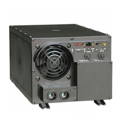
  9. Tripp Lite PowerVerter APS 1024 User manual

Tripp Lite PowerVerter APS 1024 User manual

-
IRIPP~U7E
POWER
PROTEC~ON
P
I
~
-
3
:-
'A-
-.
1111W.35lhStmt
Chicago.
lL
60609
USA
Customar
Support:
(773)8641234
www.trippliia.com
c
~pPaM'iE
POWER
PROTECTION
I
-
-
t
1111
W.
35th Street
Chicago,
IL
60609
USA
Customer Support: (773) 869-1234
www.tripplite.com
@u-l.~.rh.,
93-132s
(9m3058)
11/99
Copynpht
0
199'4
Tnpp
Lte
All
n~hts
ruervd
----
.
-
.-
-
--
-
-
-
-a__
--
-
-.
Congratulations! You've purchased the most advanced, feature-rich integrated inverter~battery
charger on the market.Your APS providesyourequipment with utility-suppliedAC power when it
is
available, andduring blackouts, overvoltagesand brownouts, your APS automatically switches
over to
an
external battery source to power connected equipment with voltage and frequency-
controlledAC power. Inadditionto reliable APS performance,your model features:
Automatic Overload Protection
Ifyou overload your APS, itwill automatically protectitself and your valuable batteriesfrom
damage.
Frequency-ControlledOutput (Invert Mode)
Your APS controls its output frequency so frequency-sensitive equipment can operate
properly.
;
Load'Sense
;
Your APS conserves battery power by shutting down its inverterwhen it is not supportinga
load.
You
can
chooseat what minimumloadyour APS will activateits inverter.
Multi-FunctionIndicatorLights
!
Several sets of multifunction indicator lights keep you constantly informed of battery charge
levels,fault conditions and APS operation.
i.
.
Multi-Operation Switches
An
array of user-configurable switches gives you convenient options when operating your
APS. You
can
selectthe voltage level at which your APS's inverterwill turn on to maximize
equipment protectionand minimizebattery drain; set your APS for maximum charging
efficiencywith your battery type; even set up your APS for remote control operation.
AutomaticVoltage Regulation(Select modelsonly)
'VR'
APS models regulate incomingAC power, 'boosting' or 'cutting' the voltageto keepyour
:
equipment runningthrough brownouts and overvoltages
without
draining
battery
power.
Stage
2
Absorption
k
4
""'d
CHARGING
P
OFlLE
Advanced, 3-Stage
Battery Charger
Your
APS
rechargesyourbatteryfaster
than conventional chargers because
its three-stage charger profile (Bulk,
Absorption and Float) are optimized,
regardless-of-the type of battery
you._^^.--
use (Wet or Gel).* In addition, the ad-
vanced charging system protects
againstover-chargeandover-discharge
to ensure a longer service
life
from
your battery.
*
7he Ahsorprion and Floor levels vary according ro barrer).
rype which is field selecrahlc
as
eirher "Wer' or "Gel' cell.
Load Sharing (Select models only)
Select APS models can be set to limit their own charging functions so they can charge their
batteries at the quickest rate possible without overloading their power input circuits.
High EfficiencyOutput
Your APS's advancedcircuitryproducesamoreefficient DC-to-ACconversion, minimizingenergy
loss. This allows you to
run
connected equipment longer between battery charges.The APS will
maintain this highly-efficient output even as the battery charge decreases.
Frequency Controlled Inverter Output
All APS models feature Frequency ControlledInverter Output which allows devicesdependent
I
on AC line frequency (such as computers, VCRs, CD players, tape recorders, clocks and
turntables) to operate properly. Your APS istherefore ideal for any of these applications:
I
I
computers kitchen appliances CD players
microwaves refrigerators VCRs
I
sump pumps electric motors lights
I
power tools tape recorders turntables
and more!
This manualcontains importantinstructions and warnings that should be followed during the
installation, operation and storage of all Tripp Lite APS Systems.
APS
LocationWarnings
Installyour APS indoors, away from excess moistureor heat, dust or direct sunlight.
Leaveadequate space around all sides of the APS for proper ventilation. The heavierthe
loadof connected equipment, the more heat will be generatedby the APS.
--
*-
Do
noti
thdPS
marmagneticstorage
media;-asthis mayresult Indata
wrmpttan~
Battery ConnectionWarnings
You must connect batteriesin order for any APS model to operate.
Multiple battery systems must be made up of batteriesof the same voltage, age, amp
hour capacity and type.
Keep batterylocationwell ventilated. Explosivehydrogen gas can accumulate near
batteries
if
they are not kept well ventilated.
Sparks may result during final battery connection.
Do not allow objectsto contactthe two DC inputterminals. Do not short or bridgethese
terminalstogether. Serious injury to property or person could result.
luipment ConnectionWarnings
I
Do
not useTripp Lite APS Systems in life support applications where a malfunctionor
failureof a Tripp LiteAPS System could cause failure or significantlyalter the perfor-
manceof a lifesupport device.
Do not connect a surge suppressor, line conditioner or UPS to the output of the APS.
Corded models: Donot remove or modifythe ground pin of the APS's plug. Do not use
Weprong adaptors with the APS's plug. Connect your APS only to a properly grounded,
three-wire AC power outlet.
Do
not plug your APS intoitself;this will damagethe APS
and
void your warranty.
nperation Warnings
Your APS does not require routine maintenance. Do not open your APS for any reason.
There are no user-serviceable parts inside.
Potentiallylethalvoltages exist within this unit as long as the batterysupply isconnected.
Duringany service work, the battery supply and AC input connection (if any) should
therefore be disconnected.
Do not connect or disconnect batterieswhile the APS is operating from the battery
supply.
CONFIGURATION DIP SWITCH SETTINGS
DIP SWITCH GROUP A (All models1
BA77ERY
TYPE/
VOLTAGEPOINT
Usinga smalltool,
set
the
4
'Battery Type
I
Voltage Point"ConfigurationDIP Switches, Group A
(locatedonthefront panel of your APS; see Diagram1,
p.
32) to select batterytype and set the
!
voltage range outside of which your APS will switch to battery power.
Select-Battery_Type
-
~p
~.-
~
~~
~
(DIP Switch #1, Group A)
'
CALITION:
TheBanery Type
DIP
Switchseningmust march rhe typeof banerirsyou connecr oryour hunericsmay hedegraded
or
damaged over
an
mended period of rime. See "Barrcry Selecrion." page
7
for more infomarion
Batkum~
&itch Posltlon
.
.
Gel Cell (Sealed) Battery
.............................
UP
Wet Cell (Vented) Battery ...........................Down* Cell
Select High AC Voltage SwitchTo Battery Point
(DIP Switch #2. Group A)
.
,
YQ&Q
Switch Pos
145V
.............................................................
UP
135V
.............................................................
Down'
Select Low AC Voltage SwitchTo Battery Point
(DIP Switches #4, Group A
&
#3,
Group A)
#4 Up
&
#3
own
#4 Down
&
#3 Up #4 Down
&
#3 Down
Mostloads will performadequately when your APS's HighAC Voltage Point DIP Switch
#2
is set
(
to 135VanditsLowAC Voltage Point DIPSwitches#3and#4are setto95V However.ifyour APS
frequentlyswitchestobatterypowerdue
to
momentaryhigMowlinevoltageswings thatwouldhave
littleeffect on equipmentoperation,you maywish to adjustthese settings. By raisingthe High AC
I
VoltageSwitchtoBatterypointand/orloweringtheLowAC Voltage Switchto Battery Point,you may
reduce the number of times your APS switches to batterydue to voltage swings.
Factory default wnings.
DIP
SWITCH
GROUP
B (Available on Select Models)
D
SHARING/EQUALIZEBATTERY CHARGE
LOAi
Using
onthc
the
'1
lasmalltool,setthemLoadSharing'ConfigurationDIPSwitches,
#1
and#2ofGroupB(located
3
front panelof your APS; see Diagram 1, p. 32). DIP Switch#3, Group B should be kept in
JP'
positionwhen you are not equalizingyour batteries'charges. DIP Switch #4, Group B
has no function.
Load Sharing
(DIP Switches #1, Group B
&
#2, Group B)
Your APS features a high-outputbatterycharger that candraw a significantamount of power
fromyour linepowersource when charging at itsmaximumrate. If anAPS is supplying itsfull
ACpowerratingtoitsconnectedloadatthesametimeasitischarging,itcouldtripitslinesource
circuitbreaker.TrippingthisbreakerwillcutoffAC powertoyourloadandstopbatterycharging.
--
-
To reducethechanceof trippingthis breaker, selectAPS modelsmaybesettoautomatically
limittheirchargeroutputtokeepthe sum of their AC loadandchargerpowerwithintheir circuit
breakers' rating.
This charger limitingfunction has four settings, allowing you to choose less charger limiting
for APS configurationswith higher rated breakers. The figures below show how to set your
DIP Switches to selecthow heavy a loadcan be placed on your APS beforecharger limiting
begins.
BatteryCharger
LimitingPoints
Chargcr limiring rakes cffecr rhe
momcnr any load is applied:
chargcr ourpur falls gradually
from
full ourpur ar
no
load ro
no
ourpvl ar full load
Thir
is rhe fa-
tory default scrring.
Most
Limiting
#1& #2 Up
Charger limiring begins when rhe
APSs load reaches 33% of rhe APSk
load raring. Charger ourpur falls
gradually from full ourpur or 33%
of rhc APSs load raring ro abour
40%
of full ourpur or full load
Less Limiting
#1 Up
&
#2 Down
Charger limiting begins ar when No charger limiring occurs ar any
rhc APSs load reaches
66%
of rhc load size.
APSs load raring. Charger ourpur
falls gradually
from
full ourpur or
66%
of rhc APSk load raring to
abour
40%
of full ourpur or full
warL Limiting
load.
No
Limiting
#1
Down
&#2 Up #1
&
#2 Down'
Equalize Battery Charge
(DIP Switch
#3,
Group B)
This DIP Switch allows you to equalize the internal resistance of your battery's cells. The
.process is automatic and once started can only be stopped by removing the input power.
SElTiNG PROCEDURE:
1) Moveto 'Equalize' (DOWN) positionfor three seconds.
2)
Moveto 'Reset' (UP) position and leave it there.
CAUTION:
Batterychargeequalizationshouldonlybeperformed instrictaccordancewith
the battery manufacturer's instructionsand speciflations.
l%m@amW
Switch Positio"1 Reset
Reset
.............................
..
...
..
...
....
...
....
.....
....
UP'
Equalize
......................................................
Down
Factory defaulr senings.
Equalize
I
Selecting BatteryType
I
I
I
Select a batteryor system of batteries that will provide your APS with proper DC voltage and an
adequate amp hour capacity: Select 'Deep-Cycle' batteries to enjoy optimum performance from
yourAPS. Batteriesof eitherWet-Cell(vented) or Gel-CelVAbsorbedGlass Mat (sealed)construction
are ideal.
6
Volt "golf-cart,"Marine Deep-Cycleor 8D Deep-Cyclebatteriesare also acceptable."
Even rhough APS models arc high-eficiency converrcrs of elecrriciry, their rared ourpur capaciries arc limircd
by
rhe amp-
hour size of rhc exrcrnal bancries.
**
You musr scr Configurarion DIP Swirch
#I.
Group
A
(Bancry Type) ro march rhr r?pe
of barrcries you connecr or your hrrcrics may bc degraded or damaged over an cxrcndcd period of rime. See 'APS
Configurarion.' page
5
for more infomarion.)
Selecting~Battery
Amp
Hour Capacity
-
~-
~
-p
-~
--
SteD
1;
Add theWattage Ratingsof your connected equipmentto determinethe TotalWattage Required.'
Stel,
2:
DividetheTotalWattage Required(fromStep1)bythebatteryvoltagetodeterminetheDCAmperes
Required.
SkfGk
Multiply the DC Amperes Required (from Step 2) by the number of hours you estimate will pass
without AC power before your batterycan rechargeto determine a Battery Amp-Hours Required
Rough Estimate."
Compensatefor inefficiencyby multiplingyour BatteryAmp-Hour Required Rough Estimate(from
Step3) by 1.2todetermine howmany amp-hoursof batterybackup(fromone or severalbatteries)
you should connectto your APS." Note that the Amp-Hour ratingsof batteriesare usually given
for a 20 hour dischargerate. Actual Amp-Hour capacitiesare lesswhen batteriesare discharged
atfaster rates: batteriesdischargedin 55 minutesprovideonly about
50%
of their listedAmp-Hour
ratings,while batteriesdischargedin
9
minutes provideas littleas 30% of their Amp-Hourratings.
Thc wanage raring
u
uually stared in rhc rquipmenr's manuals or on rhrir namcplarcs.
If
your equipmcnr
is
rared in
ampercs, conven ro warrs by mulriplying rhc ampere raring by your ~minalAC line voltage (120).
**
Your charging amps
multiplied by rhe charging hours musr crcecd rhc discharge amp-hours rakcn from rhc barrcrics bcwcen charges or you
will evcnrually run down your bancry bank.
I
(See
Diagram
2,
p.
32).
lnstalltwo 8 mm (114 in.) fasteners' into a rigid
horizontal
surface using the measurements
in the diagram. (Leavethe heads of fasteners raised slightly above the horizontalsurface in
order to engage the slots in the APS's two front feet.)
Slide APS forwardtofully engagethe fasteners inthe APS's front feet. Installtwo 8 mm (114
in.) fastenersintheAPS'stwo rearfeet.Tightentherearscrewstopermanentlyholdyour APS
in position.
I
Rccommcnded for
vehicular
insrallarion and orher applicarions requiring pcrmanenr, secure mounring. All
fmencrs arc user-supplied Turn
OFF
your APS and disconnccr ir complcrcly before mounring.
I
1.
Connect your APS's positive
DC
Terminal directlyto a fuse.
UL recommendsthat you install a recognizedUL component fuse block and fuse within 18
inchesof the battery. The fuse's rating must equal or exceed the minimum fuse rating listed
inyour APS model'sspecificationson pages 14or
15.
2
Choose a battery configuration appropriateto your batteries.
Single Battery Connection: Referto Diagram 4, page
33.
When using a single battery, its
voltagemustbeequaltothevoltageof your APS'slnverterNominal lnputVoltage (seespecs.)
ParallelBattery Connection: Referto Diagram
5,
page
33.
When usingmultiple batteries in
parallel, each battery's voltage mustbe equalto
the
voltage of your APS's Inverter Nominal
lnput Voltage (see specs.)
Series Battery Connection: Referto Diagram
6,
page
33.
When using multiplebatteries in
series, all batteries must be equal in voltage and amp hour capacity, and the sum of their
voltagesmustbeequaltothevoltageofyourAPS's lnverterNominallnputVoltage (seespecs.)
"
Use the SHORTEST and HEAVIEST
GAUGE
battery cabling.
Use#4cabling for DCcablelengthsupto 10feet. Use#2cablingfor lengthsupto
16
ft.
Shorter
andheaviergaugecablinglimits DCvoltagedropand allowsfor maximumtransfer of current.'
'APS
models ore ropublc of delivering a much higher worruge ourpur for brief periods oj rime. Wiring should be
configured
ro Wcrhis brief high-currcnr druw. Though your
APS
is u high-eficiency conveners of elecrriciry,
irs
mted
owpw
copmiry
u
limircd by rhc length
ond
gauge of rhc wires m'ngfrom rhc boncry ro rhc
APS.
.,.'
APS systems may permanentlymountedin a car, truck or boatand connectedto draw power
fromthe vehicle's battery.Note: donotconnect
a
24V
or
36V
APS
toa vehicle's battery. There
aretwo main waysto makethis sort of vehicularbatteryconnection.Choose the Basic Connection
if
you are runninglighthandtools or other smallappliancesfor abrief periodof time
(see
Diagram
7,
p.
34).
Choose the Advanced Connectionif you are using your APS to power heavy loads for
extendedperiodsof time (seeDiagram
8,
p.
34).
The Advanced Connectionincorporatesa batteq
isolatorandseparatebatterysystem to providebattery power to your APS while preventingitfrom
draining your vehicle's battery. Note: Depending on your application, you may require more than
12V
Deep Cycle Battery.
h:
Nsw
opd
pur
APS
fmm
an
&mator
wichoul
a
baifq
connecrcd
as
shown
in
Diu#mx
7
or
8,
p.
34
Pzfore AC connection,match the power requirementsof your
equipmentwith the power output of your APS to avoid overload.
When figuring the power requirements of your equipment, do not confuse 'continuous' power
ratings with 'peak' power ratings. Electric motors require more power to turn on ('peak power')
than
they requireto wn continuously.'Peak' power ratingsare usually
2
to
5
times 'Continuous'
ratings.Mostelectricmotorsrequire'peak power' onlywhentheyareturnedon. Theelecbic motors
inequipmentsuchasrefrigeratorsand sump pumps, however. constantly
turn
onandoff according
to
demand.These motorsrequire'peak power'atmultiple,unpredictabletimesduringtheir operation.
8
Hardwired ElectricalConnections
(Allhardwiremodels)
Refertotheelectricalschematic. Diagram
3
onpage
32,
for properelectricalconnectionof hardwired
APSmodels.Consultaqualifiedelectricianandfollowallapplicableelectricalcodesandrequirements.
1)Loosenscrews andremove coverplatefromyour APS's HardwireAC electricalbox. Remove
the knockout covers closest to the desired electrical source and to your equipment.
2) Thread your wires through strain reliefs and through the knockouts.
3)
Connect both input and output ground wires to the ground (green) terminal.
4)
Connect the incoming hot wire to the input hot (brown) terminal.
5)
Connectthe incomingneutralwire to the input neutral (blue)terminal.
6)
Connect the outgoing hot wire to the output hot (black)terminal.
7)
Connectthe outgoing neutral wire to the output neutral (white)terminal.
8)
Tighten and affix strain reliefs. Replace cover plate and tighten screws.
AC lnput ElectricalConnection
(Allcordedmodels)
Plugthe linecord into an outlet providing 120V AC,
60
Hz. power.Make sure that the circuit you
connect your APS to has adequate overload protection, such as a circuit breaker or a fuse.
AC
Output Electrical Connection
(Allcordedmodels)
Simply plug your equipment into the unit's AC receptacles.
Set Operating Mode Switch
1
Switch to 'AUTOIREMOTE" when you are using connected equipment. ADVANTAGE:
Provides battery backup power during blackouts or brownouts.
Note: When the swltch is in the
"AUTOIREMOTE'
position, you can operate a user-
supplied swltch to transfer between battery-backup and chargeonly modes.
(See
Remote Connector description on page
10.)
Switch to "CHARGE ONLY" when you are not using connected equipment.
(WARNING!APS will not providebatterybackup!) ADVANTAGES: A) Continuestochargebattery
when power is present, and 8) Turns OFF the APSs inverter, preventing battery drain during
blackoutsor brownouts.
Switch to "OFFto completely turn offthe APS and connectedequipment or to reset the APS
afterit has shutdown due to overloador oveheating.
This manual suits for next models

6

Other Tripp Lite AC Power Distribution manuals

Tripp Lite PowerVerter 93-1911 User manual

Tripp Lite

Tripp Lite PowerVerter 93-1911 User manual

Tripp Lite PS-606-HG User manual

Tripp Lite

Tripp Lite PS-606-HG User manual

Tripp Lite Alternative Power Sources User manual

Tripp Lite

Tripp Lite Alternative Power Sources User manual

Tripp Lite 93-2268_EN User manual

Tripp Lite

Tripp Lite 93-2268_EN User manual

Tripp Lite PDU3VSR6G60A User manual

Tripp Lite

Tripp Lite PDU3VSR6G60A User manual

Tripp Lite IS250 User manual

Tripp Lite

Tripp Lite IS250 User manual

Tripp Lite isobar HT7300PC User manual

Tripp Lite

Tripp Lite isobar HT7300PC User manual

Tripp Lite PDUMVR30NET (AG-0045) User manual

Tripp Lite

Tripp Lite PDUMVR30NET (AG-0045) User manual

Tripp Lite 93-2024 User manual

Tripp Lite

Tripp Lite 93-2024 User manual

Tripp Lite PS-606-HG User manual

Tripp Lite

Tripp Lite PS-606-HG User manual

Tripp Lite LS 600 User manual

Tripp Lite

Tripp Lite LS 600 User manual

Tripp Lite IS1000 User manual

Tripp Lite

Tripp Lite IS1000 User manual

Tripp Lite APS POWERVERTER User manual

Tripp Lite

Tripp Lite APS POWERVERTER User manual

Tripp Lite isobar DL510PC User manual

Tripp Lite

Tripp Lite isobar DL510PC User manual

Tripp Lite TLM626NS User manual

Tripp Lite

Tripp Lite TLM626NS User manual

Tripp Lite LR 604 User manual

Tripp Lite

Tripp Lite LR 604 User manual

Tripp Lite SUDC208V42P User manual

Tripp Lite

Tripp Lite SUDC208V42P User manual

Tripp Lite isobar HT7300PC User manual

Tripp Lite

Tripp Lite isobar HT7300PC User manual

Tripp Lite Line Conditioner 230V User manual

Tripp Lite

Tripp Lite Line Conditioner 230V User manual

Tripp Lite IS500 User manual

Tripp Lite

Tripp Lite IS500 User manual

Tripp Lite 93-2007 (200106010) User manual

Tripp Lite

Tripp Lite 93-2007 (200106010) User manual

Tripp Lite PDUMVR30NET (AG-0045) User manual

Tripp Lite

Tripp Lite PDUMVR30NET (AG-0045) User manual

Tripp Lite LS 604 WM User manual

Tripp Lite

Tripp Lite LS 604 WM User manual

Tripp Lite Line Conditioner 230V User manual

Tripp Lite

Tripp Lite Line Conditioner 230V User manual

Popular AC Power Distribution manuals by other brands

Furman Classic Series owner's manual

Furman

Furman Classic Series owner's manual

Unika PC Series user manual

Unika

Unika PC Series user manual

Acromag 461A Series user manual

Acromag

Acromag 461A Series user manual

Unika PD Series user manual

Unika

Unika PD Series user manual

Atlas ECM-20SH owner's manual

Atlas

Atlas ECM-20SH owner's manual

Panamax MIW-POWERKIT-PRO datasheet

Panamax

Panamax MIW-POWERKIT-PRO datasheet

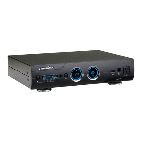
Panamax M5300-PM manual

Panamax

Panamax M5300-PM manual

KUSSMAUL AUTO-TROL 091-36 instruction manual

KUSSMAUL

KUSSMAUL AUTO-TROL 091-36 instruction manual

Monster Power Reference PowerSource HTPS7000 owner's manual

Monster Power

Monster Power Reference PowerSource HTPS7000 owner's manual

SNAP WATTBOX WB-200-1WT owner's manual

SNAP

SNAP WATTBOX WB-200-1WT owner's manual

Unika PD-1 user manual

Unika

Unika PD-1 user manual

GE AKD-10 Application guide

GE

GE AKD-10 Application guide

Furman IT-REFERENCE 7i owner's manual

Furman

Furman IT-REFERENCE 7i owner's manual

NXT Power NPT 80 user manual

NXT Power

NXT Power NPT 80 user manual

Delta A3000 user manual

Delta

Delta A3000 user manual

APT 7004 Operation manual

APT

APT 7004 Operation manual

APT LS1000 Operation manual

APT

APT LS1000 Operation manual

Furman IT-REFERENCE 20i owner's manual

Furman

Furman IT-REFERENCE 20i owner's manual

manuals.online logo
manuals.online logoBrands
  • About & Mission
  • Contact us
  • Privacy Policy
  • Terms and Conditions

Copyright 2025 Manuals.Online. All Rights Reserved.