Tritech MicronNav User manual

MicronNav System
0656-SOM-00001-07 1 © Tritech International Ltd.
MicronNav System
Product Manual
0656-SOM-00001-07

MicronNav System
0656-SOM-00001-07 2 © Tritech International Ltd.
© Tritech International Ltd
The copyright in this document is the property of Tritech International Ltd. The document is supplied by Tritech International Ltd on
the understanding that it may not be copied, used, or disclosed to others except as authorised in writing by Tritech International Ltd.
Tritech International Ltd reserves the right to change, modify and update designs and specifications as part of their ongoing
product development programme.
All product names are trademarks of their respective companies.

MicronNav System
0656-SOM-00001-07 3 © Tritech International Ltd.
Table of Contents
Help & Support ........................................................................................................... 5
Warning Symbols ........................................................................................................ 6
1. Introduction ............................................................................................................. 7
2. Technical Specification ............................................................................................ 8
2.1. System ........................................................................................................ 8
2.2. Surface MicronNav100 Interface Hub ............................................................ 9
2.3. Surface USBL Dunking Transducer ............................................................. 10
2.4. Subsea Modem Head ................................................................................. 11
3. Installing the System ............................................................................................. 12
3.1. Preparation ................................................................................................ 12
3.1.1. Using the system with the Micron INS .............................................. 12
3.1.2. Mounting the Subsea Modem Head .................................................. 12
3.1.3. Mounting the Surface USBL Dunking Transducer .............................. 13
3.1.4. Electrical Connections to the Subsea Modem Head ........................... 15
3.1.5. Electrical Connection to the Surface USBL Dunking Transducer ......... 16
3.1.6. Electrical Connection to the Surface MicronNav100 Interface Hub ....... 16
3.1.7. External Computer Data Link Electrical Connections .......................... 16
3.2. Installation .................................................................................................. 17
3.2.1. System requirements ....................................................................... 17
3.2.2. Installing Seanet Pro ....................................................................... 17
3.2.3. Surface Hardware Installation and Configuration ................................ 19
3.2.4. Subsea Hardware Responder Configuration ...................................... 21
3.2.5. Subsea Hardware Transponder Configuration ................................... 28
3.2.6. Connecting optional third party GPS Receiver ................................... 29
3.2.7. Connecting optional third party High Accuracy Heading/Pitch/Roll
MRU Sensors ........................................................................................... 31
3.2.8. Data Input from an ROV .................................................................. 41
3.2.9. Connecting optional third party Video Camera ................................... 43
3.3. Remote Beacons ........................................................................................ 47
3.4. Dry System Check ..................................................................................... 50
3.4.1. Setting up the Application ................................................................ 50
3.4.2. Transducers and integral Heading/Pitch/Roll Sensor Check ................ 50
3.4.3. Optional third party GPS Comms Check ........................................... 52
3.4.4. Optional third party Heading & MRU Check ....................................... 52
3.4.5. Optional third party Video Check ...................................................... 53
3.5. Hardware Reset ......................................................................................... 53
4. Operation .............................................................................................................. 55
4.1. Mobilising the System ................................................................................. 55
4.1.1. Pre Dive Checks ............................................................................. 55
4.1.2. Deploying the USBL Head ............................................................... 55
4.1.3. Measuring the Installation Offsets ..................................................... 55
4.1.4. Creating a New Job (Using Wizard) .................................................. 56
4.1.5. Editing an Existing Job .................................................................... 62
4.1.6. Loading an Old Job ......................................................................... 63
4.1.7. Job Settings for Mobile or Fixed Platforms ........................................ 64
4.1.8. Applying a Geodetic Datum Shift to the reference co-ordinates ........... 70
4.1.9. Launching the Subsea Installation .................................................... 77
4.2. Operating the System ................................................................................. 78
4.2.1. User Controls .................................................................................. 78
4.2.2. The Readings Explained .................................................................. 79
4.2.3. User Features ................................................................................. 79
4.2.4. Other Controls ................................................................................. 84
4.3. Logging and Replay ................................................................................... 86
4.4. Shutting Down the System .......................................................................... 86
5. Maintenance ......................................................................................................... 87

MicronNav System
0656-SOM-00001-07 4 © Tritech International Ltd.
6. Adding and Using User Bitmap Charts ................................................................... 88
6.1. Adding a Chart ........................................................................................... 88
6.2. Editing a Chart ........................................................................................... 90
6.3. Deleting a Chart ......................................................................................... 91
6.4. Chart controls ............................................................................................ 91
6.5. Markers ..................................................................................................... 92
6.5.1. Overview ......................................................................................... 92
6.5.2. Creating and Laying a Marker .......................................................... 92
6.5.3. Saving the Markers .......................................................................... 93
6.5.4. Loading the Markers ........................................................................ 96
6.6. Other Chart Functions ................................................................................ 96
6.7. Load BSB Charts ..................................................................................... 100
7. Using the External Computer Data Link ................................................................ 105
7.1. Setting the RemV4 string output ................................................................ 105
7.2. List of Current String Formats ................................................................... 108
7.2.1. Proc XYZ ...................................................................................... 109
7.2.2. Raw XYZ ...................................................................................... 111
7.2.3. TP-2EC ......................................................................................... 113
7.2.4. Simrad HPR 300P ......................................................................... 114
7.2.5. Simrad HPR 410 ........................................................................... 115
7.2.6. NMEA $RATTM ............................................................................. 117
7.2.7. NMEA $GPGGA ............................................................................ 119
7.2.8. NMEA $GPGLL ............................................................................. 121
7.2.9. NMEA $GPRMC ............................................................................ 121
7.2.10. $PSIMSSB .................................................................................. 123
7.2.11. NMEA $GPDBT ........................................................................... 125
7.2.12. Notes .......................................................................................... 126
8. Using with Other Tritech Sonars .......................................................................... 127
9. Adding a Micron Echosounder ............................................................................. 128
10. Adding a Micron INS ......................................................................................... 130
11. Conversion Between MicronNav Responder and Transponder ............................. 131
11.1. Seanet Setup for Conversion .................................................................. 131
11.2. Conversion to Transponder ..................................................................... 133
11.2.1. Enabling the USBL Transducer Transponder Transmitter ................ 134
11.2.2. Configure Seanet Pro for Transponder Mode ................................. 134
11.3. Conversion to Responder ........................................................................ 136
11.3.1. Connect the Micron Sonar and Responder .................................... 137
11.3.2. Configure Seanet Pro Responder Mode ........................................ 139
Glossary ................................................................................................................. 142
MicronNav System
0656-SOM-00001-07 5 © Tritech International Ltd.
Help & Support
First please read this manual thoroughly (particularly the Troubleshooting section, if present).
If a warranty is applicable, further details can be found in the Warranty Statement, 0080-
STF-00139, available upon request.
Tritech International Ltd can be contacted as follows:
Mail Tritech International Ltd
Peregrine Road
Westhill Business Park
Westhill, Aberdeenshire
AB32 6JL, UK
Telephone ++44(0)1224 744 111
Fax ++44(0)1224 741 771
Email [email protected]
Website www.tritech.co.uk
Prior to contacting Tritech International Ltd please ensure that the following is available:
1. The Serial Numbers of the product and any Tritech International Ltd equipment connected
directly or indirectly to it.
2. Software or firmware revision numbers.
3. A clear fault description.
4. Details of any remedial action implemented.
Contamination
If the product has been used in a contaminated or hazardous environment you
must de-contaminate the product and report any hazards prior to returning the
unit for repair. Under no circumstances should a product be returned that is
contaminated with radioactive material.
The name of the organisation which purchased the system is held on record at Tritech
International Ltd and details of new software or hardware packages will be announced at
regular intervals. This manual may not detail every aspect of operation and for the latest
revision of the manual please refer to www.tritech.co.uk
Tritech International Ltd can only undertake to provide software support of systems loaded
with the software in accordance with the instructions given in this manual. It is the customer's
responsibility to ensure the compatibility of any other package they choose to use.
MicronNav System
0656-SOM-00001-07 6 © Tritech International Ltd.
Warning Symbols
Throughout this manual the following symbols may be used where applicable to denote any
particular hazards or areas which should be given special attention:
Note
This symbol highlights anything which would be of particular interest to the reader
or provides extra information outside of the current topic.
Important
When this is shown there is potential to cause harm to the device due to
static discharge. The components should not be handled without appropriate
protection to prevent such a discharge occurring.
Caution
This highlights areas where extra care is needed to ensure that certain delicate
components are not damaged.
Warning
DANGER OF INJURY TO SELF OR OTHERS
Where this symbol is present there is a serious risk of injury or loss of life. Care
should be taken to follow the instructions correctly and also conduct a separate
Risk Assessment prior to commencing work.

MicronNav System
0656-SOM-00001-07 7 © Tritech International Ltd.
1. Introduction
The Tritech MicronNav system is an innovative Ultra Short Base Line (USBL) acoustic
tracking system designed for tracking or marking the position of underwater vehicles or
objects. The design of the system provides 180° hemispherical coverage from the surface
unit and 360° omni-directional coverage from the subsea unit enabling continuous reliable
tracking even in very shallow water. The size of the subsea unit is small enough to be fitted
to the smallest of observation class vehicles.
The system can be used stand-alone in Transponder mode in which case the subsea unit
only requires power, or it can be used with Tritech's range of imaging Sonars (Micron MKII
or MKIII, Super SeaKing and Gemini) in responder mode in which case the subsea unit is
powered by and communicated with through the Sonar Aux port. It is synchronised with the
Sonar to reduce the effect of acoustic interference on the sonar display. For compatibility
with other Tritech International Ltd Sonars see Chapter 8, Using with Other Tritech Sonars
The MicronNav system consists of a Seanet Pro application software package for installation
onto a suitable PC or laptop computer, a small surface MicronNav100 Interface Hub, a
lightweight surface USBL ‘Dunking’ Transducer (with integral magnetic compass and pitch/
roll sensor) and one or more small subsea MicronNav Modem heads.
Note
The Tritech SeaHub Surface Interface Module cannot be used in place of the
MicronNav100 Hub.
The Seanet Pro application software running on a PC or Laptop commands the subsea
MicronNav Modem head to transmit an acoustic ranging signal to the Surface USBL
Dunking Transducer. When operating in stand-alone Transponder mode this command is
sent acoustically via the USBL Dunking Transducer, and when combined with the Tritech
sonar and operating in Responder mode this command is sent electronically via the sonar
communications link.
The MicronNav acoustic ranging signal is detected by the USBL Dunking Transducer and
MicronNav100 Hub Interface module and the received signal information sent to the host
Seanet computer for calculation of range and bearing of the subsea head. USBL Dunking
Transducer pitch/roll and heading data from the integral pitch/roll sensors and magnetic
compass are also captured and sent to Seanet Pro for calculation of corrected position to
world axis.
If GPS positional data is available the range and bearing of the subsea head is synchronised
and the Seanet display updated with ships position and ROV position to true world position.
Provision is made to allow position information to be overlaid onto a user supplied bitmap
chart display of the local area if required.
The position fixing cycle is repeated dependent upon the selected update rate (0.5 – 10s).

MicronNav System
0656-SOM-00001-07 8 © Tritech International Ltd.
2. Technical Specification
2.1. System
Positioning Technology Spread Spectrum Acoustic Ultra Short Baseline (USBL) Range/
Bearing Tracking System. 20-28 kHz band. (Magnetic Compass
and Pitch/Roll Sensor built into Dunking transducer as standard)
Tracking Range 500m (1,640ft) typical Horizontal, 150m (492ft) typical Vertical.
Range is dependent on a variety of operating conditions:
• The presence of thermoclines
• The presence of acoustically reflecting surfaces within the
operating environment
• Ambient noise
• Salinity
• Volume reverberation
• Surface and seabed reflectivity
Range Accuracy +0.2 metre (7.87 inches) system timing accuracy – assuming
correct Velocity of Sound.
Bearing Accuracy +/-3 degrees (equates to better than +5% of slant range)
Position Update Rate 0.5 Seconds – 10 Seconds
Targets Tracked Maximum 1 Responder and 15 Transponders
Data Display Plan Position Indicator (PPI) display and optional user bitmap
chart display
Data Recording All Data recorded in standard Seanet Format for Replay or
Analysis
Surface Navigation NMEA 0183 GPS and Heading/Attitude Sensors supported.
Position of Surface vehicle displayable.

Technical Specification MicronNav System
0656-SOM-00001-07 9 © Tritech International Ltd.
2.2. Surface MicronNav100 Interface Hub
AC Power Supply 90V to 264V, 47Hz to 63Hz. IEC-320 C14 socket (for C13 cord),
20x5mm 2A Antisurge (T) fuse
DC Power Supply 12V to 36V, 2.1mm (0.08”) pin (positive centre).
Power Consumption 4.8W from either source (with no external load)
DC Power Output (Port
D & AIF Port)
50W or 2A maximum current draw
Internal 20mm x 5mm 2A Quick Acting (F) fuse.
+33V if using AC, 1.5V less than the supply voltage if using DC.
Defaults to highest voltage if both are connected.
Supported Protocols USB2.0, RS232, RS422, RS485, ARCNET LAN.
Ports A, B and C DE-9 male connectors
RS232 (3 wire), RS485 (half duplex) on Ports A, B, C
RS232 (5 wire – RTS, CTD) on Port A
RS422 (full duplex differential) on Port B
ARCNET differential (analogue) LAN on Port C
Port D DIN-45322 Female Socket, screened with power & earth.
RS232 (3 wire), RS485 (half duplex)
ARCNET differential (analogue) LAN
AIF (ARCNET) Port DA-15 female connector
ARCNET differential (analogue) LAN
ARCNET TTL LAN (for backplane connection)
Optional support for “Port A” serial signals
Power output available
USB 2.0 480Mbps Ports One Type B on rear for PC connection.
Two Type A ports on front for auxiliary devices.
500mA over-current protected +5V on front ports.
Avoid USB hubs and cables exceeding 5m.
RAT Connection A single DE-9 female front panel connector for connection to a
“V2” Remote Access Terminal.
Transducer Connection DB-25 female port on rear panel for connecting the MicronNav
USBL Dunking Transducer.
Status Indicators 1 x Power/Status Indicator
4 x Communication Status Indicators (Red/Green)
11 x Communication Hardware Mode Indicators (Blue)
Dimensions Width: 232mm, Height: 52mm, Depth: 185mm
Weight 1.3Kg
Material Painted Aluminium, Matte Anthracite Textured Finish
IP Rating IP20 (no protection against water ingress).
Temperature Limits -10°C to 35°C (operation), -20°C to 50°C (storage)

Technical Specification MicronNav System
0656-SOM-00001-07 10 © Tritech International Ltd.
2.3. Surface USBL Dunking Transducer
Operating Beamwidth 180 degrees
Power requirement No external requirement – is supplied directly from
MicronNav100 Interface Hub
Comms requirement No external requirement – is connected directly to
MicronNav100 Interface Hub
Frequency of operation 20-28kHz Spread Spectrum
Depth Rating 10metres (32.8 feet)
Cable Length standard 10metres (32.8 feet) - other options available on
request
Maximum Cable Length 50metres (164 feet)
Maximum Diameter 110mm (4.33 inches) including mounting plate
Body Tube Diameter 75mm (2.95 inches)
Maximum Height 270mm (10.63 inches)
Weight in Air 1.96kg (3lbs 15oz)
Weight in Water 810g (1lb 12oz)
Material Mounting Flange: Marine Brass
Housing: Grey ABS
Transducer: Polyurethane
Operating Temperature -10°C to +35°C
Storage Temperature -20°C to +50°C

Technical Specification MicronNav System
0656-SOM-00001-07 11 © Tritech International Ltd.
2.4. Subsea Modem Head
Operating Beamwidth Omni directional Transducer
Power Requirement 12-48V DC
Note: Reverse and over-voltage protection are not provided to
the power supply.
Frequency 20-28kHz Spread Spectrum
Power Consumption Dependent on the system interrogation rate which is user
controlled (0.5, 1, 2, 5 or 10sec) for example at 1sec update the
average power consumption would be 175mW typical and at
0.5sec would be 350mW typical.
Main Port Type factory set to RS232
Note: Transient and over-voltage protection is applied to the
Comms ports but Comms ports are not DC isolated.
Main Port data rate factory set to 9600 baud (others available on request)
Aux Port Type factory set to RS232
Aux Port data rate factory set to 9600 baud (others available on request)
Depth Rating 750m (2,460ft)
Maximum Diameter 56mm (2.20 inches)
Maximum Height 76mm (2.99 inches)
Fixing Points 4 off M3 x 0.5 Tap 5.0 full thread
Weight in Air 210g (7.4oz)
Weight in Water 55g (1.9oz)
Material Housing: Anodised Aluminium
Transducer: Polyurethane
Operating Temperature -10°C to +40°C
Storage Temperature -20°C to +50°C
Caution
This specification refers to the Micron Nav Modem. The Micron Range (Sonar/
Seasprite, Echosounder, Micron Nav Modem) work on a voltage range of 12-48V
DC with the exception of the Micron Data Modem which uses 12-24V DC. If you
are unsure which product you are using either opt for a lower voltage or contact
Tritech International Ltd to discuss product options.
MicronNav System
0656-SOM-00001-07 12 © Tritech International Ltd.
3. Installing the System
3.1. Preparation
This section is intended to provide the user with sufficient information to allow for the
consideration and preparation of mounting brackets and wiring arrangements prior to receipt
of the system, final wiring however can only be completed once in receipt of the system as
interconnect leads are supplied with the system.
3.1.1. Using the system with the Micron INS
The Tritech Micron INS has been designed to be fully compatible with the MicronNav System
and can be integrated in a variety of ways.
For full details of how to install a Tritech Micron INS with the MicronNav please refer to
the Micron INS Product Manual (document reference: 0722-SOM-00001) alongside this
document.
3.1.2. Mounting the Subsea Modem Head
The Subsea Modem Head should be mounted at the top of the ROV ensuring the transducer
is proud of the ROV fairing with a clear view from the transducer to the surface, also
remembering to ensure enough room is left to enable the cable connection to be made to the
Micron connectors. To assist with the mounting there are 4 off M3 x 0.5 tapped 5.0 deep full
thread fixing holes in the base of the unit (note: these are protected with plastic grub screws
when shipped from the factory and should be removed prior to using). An alternative method
of mounting the head is to gently grip with a 50mm diameter clamping mechanism around
the bottom part of the housing (in this case the plastic grub screws fitted to the fixing holes
should be left in place).
Caution
It is recommended that any fixing screws used should be of non-metallic material
to reduce the risk of corrosion around the fixing positions.

Installing the System MicronNav System
0656-SOM-00001-07 13 © Tritech International Ltd.
24.0
56 A/F
Ø50
66
Ø49
Ø56
76
16
26
24.0
4 OFF M3 x 0.5
4.5
3.1.3. Mounting the Surface USBL Dunking Transducer
The USBL Dunking Transducer should be mounted from the fixed platform/dockside or
mobile platform/vessel such that the transducer head is at least 1m to 2m below the surface
of the water and at least 1m to 2m away from the dock wall or vessel, if operating from a
vessel it may be difficult to achieve 1m to 2m clearance from the side so in this case lower
the head deeper to ensure a clearance of 1m to 2m below the bottom of the hull.
Caution
The depth of the head must not exceed 10m. Also, when installing on a vessel it
is important to ensure the head is mounted clear of any propellers or thrusters.
The USBL Dunking Transducer contains an integral Magnetic Heading and Pitch/Roll Sensor
that enables the MicronNav Seanet application software running on the surface computer
to make corrections to world axis, this is particularly effective when operating from a non-
magnetic mobile platform/vessel or fixed dockside.
When operating from a steel hull vessel the integral sensor will be affected by magnetic
interference from the vessel and it is recommended in this type of installation that an external
Ships Compass & Motion Reference Unit (MRU) is used to provide the Heading and Pitch/
Roll information, details of how to connect and use an external Compass & MRU sensor can
be found in Section 3.2.7, “Connecting optional third party High Accuracy Heading/Pitch/Roll
MRU Sensors”.

Installing the System MicronNav System
0656-SOM-00001-07 14 © Tritech International Ltd.
The USBL Dunking Transducer is supplied with a short mounting pole (0.5m long) that will
screw into the 22mm diameter coupling on the top of the USBL Head mounting flange and
provide a clamping point for attaching to the users installation. The mounting flange coupling
is a standard 22mm water pipe fitting (UK) enabling a standard 22mm diameter copper water
pipe to be used as a mounting pole fitting directly to the head.
An alternative method of mounting the head is to fabricate a dedicated mounting bracket
and fasten to the USBL mounting flange. It is recommended however that a non-magnetic
material is used for the fixing so as not to affect the integral Magnetic Heading and Pitch/
Roll sensor, if the user wishes to use stainless steel for the fabrication some Duplex Alloys
such as FerraliumSD40 are particularly good but are rather exotic, stainless steel 316 (typical
material used for sub-sea housings) however has little effect on the compass readings and
could be used as an alternative.
Caution
When operating from a vessel consideration should be given to the speed the
vessel is likely to be travelling and the resultant force/pressure the USBL Dunking
Transducer mounting arrangement will need to withstand.
The yellow line indicates the front of
transducer head. This should be positioned
facing in the required forward position to
ensure correct representation on the PPI
display when set to “Ships Head Up”. If
operating from a fixed platform/dockside this
would normally be facing away from the
platform/dockside and if operating from a
mobile platform this would normally align with
the front of the vessel.

Installing the System MicronNav System
0656-SOM-00001-07 15 © Tritech International Ltd.
Ø 26.6 THRU ALL
1 1/8" - 14 UNS THRU ALL
33.0
40.05 TYP
20.0 TYP
3 x Ø 6.5 THRU ALL
4 x Ø 6.5 THRU ALL
15.0
46.25 23.13 TYP
20.0 TYP
Ø 110.0
71.0
Ø 33.0
16.0
3.1.4. Electrical Connections to the Subsea Modem Head
Responder Mode
In Responder mode there is no direct connection from the ROV to the sub-sea Modem head
- in this configuration the ROV connects to the Tritech Sonar head (Main port) using the cable
supplied with the Sonar, and the MicronNav sub-sea Modem head (Main port) connects to
the (Auxiliary port) of the Sonar using the Double Ended Interconnect cable supplied with
the MicronNav system.
Transponder Mode
In Transponder mode the MicronNav subsea Modem head only requires power supply
connections - this can be from the ROV, a stand-alone underwater battery pack or from the
Auxiliary port of any of the Tritech subsea heads.
12
643
5
Face View
Connector
Pin Wire Colour Function
1 Yellow not connected
2 Blue not connected
3 Red Supply +
4 Black Supply Ground
5 Green not connected
6 cable sheath Earth/Screen
Installing the System MicronNav System
0656-SOM-00001-07 16 © Tritech International Ltd.
3.1.5. Electrical Connection to the Surface USBL Dunking Transducer
The USBL Dunking Transducer is supplied complete with underwater cable moulded directly
onto the head and a DB-25 connector at the dry side for connection directly into the USBL
connector on the rear of the MicronNav100 Interface Hub.
3.1.6. Electrical Connection to the Surface MicronNav100 Interface Hub
The surface MicronNav100 Interface Hub requires power from a 90 to 264V AC supply 47
to 63Hz, or a 12 to 36V DC supply - power consumption from either source will be typically
4.8W (with no additional external device load).
Communications from the MicronNav100 Interface Hub to the Subsea head (if being used
with Micron/SeaSprite Sonar) is via a DE-9 socket which connects to Port B plug on the rear
of the unit.
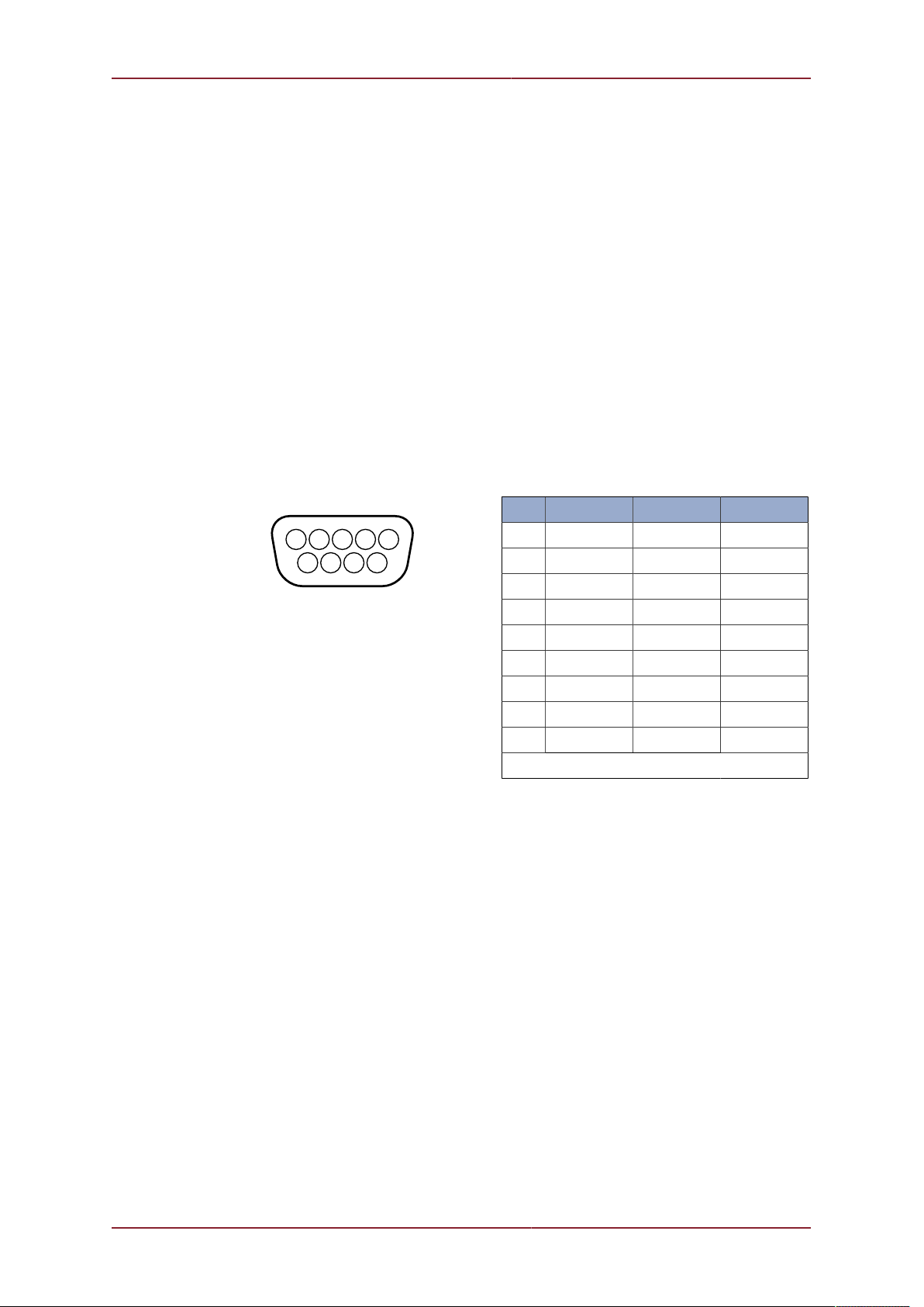
Connections to the DE-9 socket on Port B are as follows:-
45
12
8
6
3
7 9
Pin RS232 RS422 RS485
1 ‡ ‡ ‡
2 RX TX.A TX/RX.A
3 TX TX.B TX/RX.B
4 ‡ ‡ ‡
5 GROUND GROUND GROUND
6 ‡ ‡ ‡
7 ‡ RX.B ‡
8 ‡ RX.A ‡
9 ‡ ‡ ‡
‡ = connected for handshaking only.
Communications from the MicronNav100 Interface Hub to the computer running the
MicronNav Seanet application software is via a USB Type-A to Type-B cable supplied with
the system, connection is to the rear of the unit.
3.1.7. External Computer Data Link Electrical Connections
If the MicronNav data is required by a third party software package running on an external PC
then connection from the Surface MicronNav100 Interface Hub to the external PC is made
via one of the four serial interface connectors located at the rear of the unit, Port A, B, C or
D. (Note: If the system is being used in Responder mode Port B will be used for the Sonar
communications and will not available for this).
If ports A, B or C are to be used for external communications a DE-9 socket should be wired
as above, if port D socket is to be used a DIN-45322 (6 pin) plug is required and should be
wired as follows:

Installing the System MicronNav System
0656-SOM-00001-07 17 © Tritech International Ltd.
4
1
3
2
6
5
Pin RS232 RS485
1 RX TX/RX-A
2 TX TX/RX-B
3 ‡ ‡
4 ‡ ‡
5 GROUND GROUND
6 ‡ ‡
‡ = connected for handshaking only.
Warning
The 6 pin DIN-45322 connector Port D has a live 24V supply output on pin 3
referenced to 0V on pin 4.
3.2. Installation
3.2.1. System requirements
Seanet Pro has the following system requirements:
Minimum Recommended
Processor 2GHz 2GHz dual core
RAM 1GB 2GB
Graphics 3D hardware accelerated graphics card.
Display 1280x1024 (32bit colour) 1600x1200 (32bit colour)
Disk space Install is 20MB, greater than 160GB recommended for log files
Networking 100Mbit·s-1 (fast Ethernet) 1000Mbit·s-1 (Gigabit Ethernet)
Software Windows XP 32bit Windows 7 32 or 64bit
It is highly recommended that your system specifications are checked against these
requirements prior to attempting installation of Seanet Pro.
3.2.2. Installing Seanet Pro
Seanet Pro is supplied on a CD-ROM which has been designed to auto-run upon
disc insertion. The latest commercial release of software is always available from
www.tritech.co.uk.
Once loaded, the main menu of the CD will be shown on screen.

Installing the System MicronNav System
0656-SOM-00001-07 18 © Tritech International Ltd.
Click on the Seanet Pro button and the following screen will display all the appropriate
software packages for installation.
Click on the appropriate installation option and then follow the onscreen prompts and
instructions.
•Seanet Pro using AIF Card - select this option if you are using a SCUv4, or PC
equiped with a PCI AIF card.
•Seanet Pro using RS232 - select this option if you are using a SeaHub, MicronNav
Hub, PC or Laptop with either hardware COM Ports or USB converters.
•Hammerhead - this option installs a modified version for use with the Super SeaKing
Hammerhead sonar.
•Dumplog - this option installs an additional software package for post-processing data files.
Installing the System MicronNav System
0656-SOM-00001-07 19 © Tritech International Ltd.
•Task Scheduler - this option installs an additional software package to automate the
recording of logfiles with Seanet Pro.
•Sonar Image Tiler - this option installs an additional software package that can mosaic
sonar imagery from Seanet Pro onto background images.
Note
Do not attempt to remove the CD-ROM from your computer during the installation
process.
3.2.3. Surface Hardware Installation and Configuration
Caution
The power should be turned off before making a connection between the sonar
head and surface controller (SCU or SeaHub).
Carefully unpack the system from the transit case and uncoil the USBL cable, the
MicronNav100 Hub is located underneath the lift out section containing the Subsea Modem
Head and cable assemblies.
If the supplied mounting pole is to be utilised fit it to the standard plumbing fitting on the brass
mounting plate on top of the USBL Head and connect the USBL Head cable connector to the
DB-25 socket on the rear panel of the MicronNav100 Hub.
Note
It is recommended to wait until after the system has been fully configured and
the Dry System check completed before fitting the USBL Dunking Transducer to
the desired mounting arrangement.
Connect the computer USB port on the rear panel of the MicronNav100 Hub to a USB 2.0
port on the User computer with the supplied USB cable assembly.
Connect power to the MicronNav100 Hub and switch on. The indicator LEDs on the front of
the unit will flash and the ports will auto-install on the computer - this will take a minute or so
to complete and you may be prompted to re-boot the computer.
The Seanet software must now be configured for the MicronNav100 Hub – click the Seanet
Setup icon on the desktop to run the Seanet setup program, select Utilities from the top
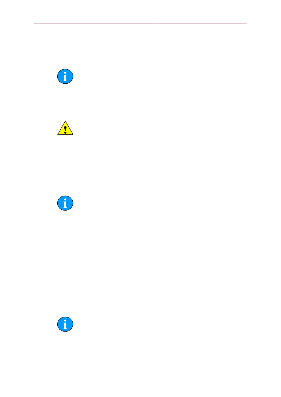
menu bar of the Seanet Setup window followed by Com Setup from the sub-menu to open
the Channel Setup page, a dialog box will be opened notifying detection of the SeaHub
on one of the COM ports and you will be asked to confirm Auto Enable of an Aif device - this
should be confirmed by selecting YES. The Channel Setup page will then automatically add
and enable the ports that are required as shown below.
Note
Port numbers may differ on different computers dependent on Windows setup.
Installing the System MicronNav System
0656-SOM-00001-07 20 © Tritech International Ltd.
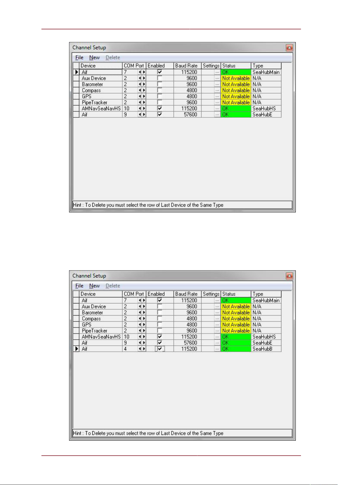
Now add a port for the Micron or SeaSprite Sonar connection for use when Responder mode
operation is required. This is done by selecting New from the menu bar followed by Aif from
the sub-menu. The new Aif device must now be configured to Port B by adjusting the COM
Port number with the spin edit button until the Type=”SeaHubB” as shown below, click the
check box to enable and close the ‘Channel Setup’ page by clicking the ‘X’ at the top right
of the window.
Table of contents
Other Tritech Marine Equipment manuals


Popular Marine Equipment manuals by other brands


EMS
EMS FireCell FC-171-001 installation guide

Raymarine
Raymarine ST40 Quick reference guide

Hosiden Besson
Hosiden Besson Banshee Excel Lite Xenon Product sheet

Beijer Electronics
Beijer Electronics X2 marine 15 - B2 HB manual

Risco
Risco WL S52 Installation and programming instructions

Furuno
Furuno IF-7000 Operator's manual


