O-O-O-O-O
O-O-O-O-|
O-O-O-|-O
O-O-|-O-O
O-O-O-|-|
O-O-|-O-|
O-O-|-|-|
O-|-O-O-O
O-|-O-O-|
O-|-O-|-O
O-|-O-|-|
O-|-|-O-O
O-|-|-O-|
O-|-|-|-O
O-|-|-|-|
|-O-O-O-O
|-O-O-O-|
|-O-O-|-O
|-O-O-|-|
|-O-|-O-O
|-O-|-O-|
|-O-|-|-O
|-O-|-|-|
|-|-O-O-O
|-|-O-O-|
|-|-O-|-O
|-|-O-|-|
|-|-|-O-O
|-|-|-O-|
|-|-|-|-O
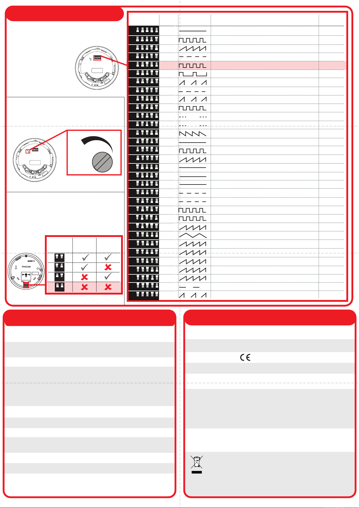
Configuration continued
Sounder /
Visual Indicator
All 32 available
configurations are shown
in the tone table.
Volume (set on sounder/visual indicator)
Audio monitoring (Set on wireless module)
The sound output of the unit can also be
reduced by adjusting the potentiometer as
shown.
www.emsgroup.co.uk
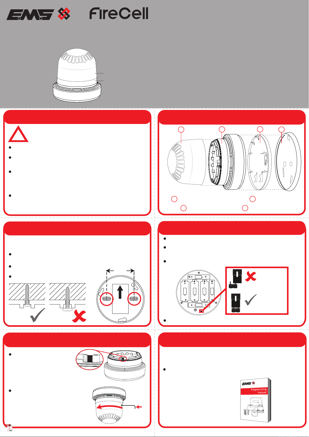
Wireless Sounder Base
PRESS HERE TO
LOG ON
IDENT
ON
OFF
2
2
ON
OFF
ON
2
ON
1
1
1
SWITCHES
1 & 2
PRIMARY
TONE
MONITORED
SECONDARY
TONE
MONITORED
The primary and secondary stage sounder
tones can be monitored. If enabled and no
audio is detected within 10 seconds upon
sounder activation, a fault is indicated at the
control panel.
OFF
OFF
Sounder tone (set on sounder/visual indicator)
Default setting: primary tone 5
Default setting: high volume
Default setting: audio monitoring disabled
1
4
1
1
9
1
19
1
1
1
18
1
1
1
1
18
19
19
1
1
1
1
18
18
1
1
1
1
8
TONE
5.
6.
7.
8.
9.
10.
11.
12.
13.
14.
15.
16.
17.
18.
19.
20.
21.
22.
23.
24.
25.
26.
27.
28.
29.
30.
31.
32.
TONE TYPE TONE DESCRIPTION / APPLICATION
1. 970Hz
2. 800Hz/970Hz @ 2Hz
800Hz - 970Hz @ 1Hz
970Hz 1s OFF / 1s ON
970Hz, 0.5s / 630Hz, 0.5s
554Hz, 0.1s / 440Hz, 0.4s (AFNOR NF S 32 001)
500 - 1200Hz, 3.5s / 0.5s OFF (NEN 2575:2000)
8.
420Hz 0.625s ON / 0.625s OFF (Australia AS1670 Alert tone)
500 - 1200Hz, 0.5s / 0.5s OFF x 3 / 1.5s OFF (AS1670 Evacuation)
550Hz / 440Hz @ 0.5Hz
970Hz, 0.5 ON / 0.5s OFF x 3 / 1.5s OFF (ISO 8201)
2850Hz, 0.5s ON / 0.5s OFF x 3 / 1.5s OFF (ISO 8201)
1200Hz - 500Hz @ 1Hz (DIN 33 404)
14. 400Hz
550Hz, 0.7s / 1000Hz, 0.33s
1500Hz - 2700Hz @ 3Hz
17. 750Hz
18. 2400Hz
19. 660Hz
660Hz 1.8s ON / 1.8s OFF
660Hz 0.15s ON / 0.15s OFF
510Hz, 0.25s / 610Hz, 0.25s
800 / 100Hz 0.5s each (1Hz)
250Hz - 1200Hz @ 12Hz
500Hz - 1200Hz @ 0.33Hz
2400Hz - 2900Hz @ 9Hz
2400Hz - 2900Hz @ 3Hz
800Hz - 970Hz @100Hz
800Hz - 970Hz @ 9Hz
800Hz - 970Hz @ 3Hz
800Hz, 0.25s ON / 1s OFF
500Hz - 1200Hz, 3.75s / 0.25s OFF (AS2220)
PRIMARY
TONE
The 5 way switch is used to configure the
sounder tone.
1 2 3 4 5
ON
12 3 4
ON
5
12 3 4
ON
5
12 3 4
ON
5
12 3 4
ON
5
12 3 4
ON
5
12 3 4
ON
5
12 3 4
ON
5
12 3 4
ON
5
12 3 4
ON
5
12 3 4
ON
5
12 3 4
ON
5
12 3 4
ON
5
12 3 4
ON
5
12 3 4
ON
5
12 3 4
ON
5
12 3 4
ON
5
12 3 4
ON
5
12 3 4
ON
5
12 3 4
ON
5
12 3 4
ON
5
12 3 4
ON
5
12 3 4
ON
5
12 3 4
ON
5
12 3 4
ON
5
12 3 4
ON
5
12 3 4
ON
5
12 3 4
ON
5
12 3 4
ON
5
12 3 4
ON
5
12 3 4
ON
5
ON
1 2 3 4 5
SWITCHES
1-5
235 6 7
ON
12345
MAX
MIN
MAX
MIN
235 6 7
ON
12345
MAX
MIN
Operating
temperature -10 to +55 °C
Storage
temperature 5 to 30 °C
Humidity 0 to 95% non-condensing
Supply 3x AA Alkaline (Panasonic LR6AD Powerline / Varta
4006 Industrial) 3x C Alkaline (Panasonic LR14AD
Powerline / Varta 4014 Industrial)
CAUTION!
Fitting of an incorrect battery type invalidates the product certification and
may result in poor performance.
Sounder output 99 dBA at 1 m (as dispatched)
IP rating IP54
Operating frequency 868 MHz
Output transmitter
power Auto adjusting 0 to 14 dBm (0 to 25 mW)
Dimensions (Ø x D) 120 mm x 125 mm
Weight 0.65 kg
Location Type A: For indoor use
2012/19/EU (WEEE directive):
Products marked with this symbol cannot be disposed
of as unsorted municipal waste in the European Union.
For proper recycling, return this product to your local
supplier upon purchase of equivalent new equipment,
or dispose of it at designated collection points. For
more information see www.recyclethis.info
European union
directives
EMS declares that this device is in compliance with
Directive 2014/53/EU. The full text of the EU
declaration of conformity is available at the following
internet address: www.emsgroup.co.uk
Approved to See part listing for associated products:
EN54-3:2001. Incorporating Amendments Nos. 1 and
2. Fire detection and fire alarm systems. Part 3: Fire
alarm devices - Sounders.
[1]
EN54-25:2008. Incorporating corrigenda September
2010 and March 2012. Fire detection and fire alarm
systems. Part 25: Components using radio links.
[2]
Certification
Certification body
CPR DoP See part listing for associated products:
[1]0359-CPR-0022,
[2]0359-CPR-0040
0905
Carrier Manufacturing Polska Sp. Z o.o. Ul. Kolejowa
24. 39-100 Ropczyce, Poland
Manufacturer
Year of
manufacture See devices serial number label
10
Specification Regulatory Information
Sounder /
Visual Indicator
©2021 EMS Ltd. All rights reserved Page 1 of 2 TSD047-99 Iss 16 23/11/2021 AJM