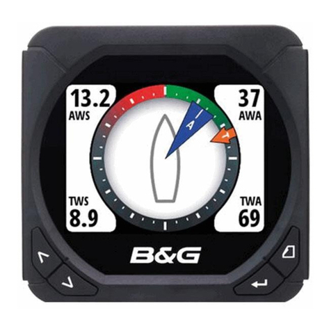
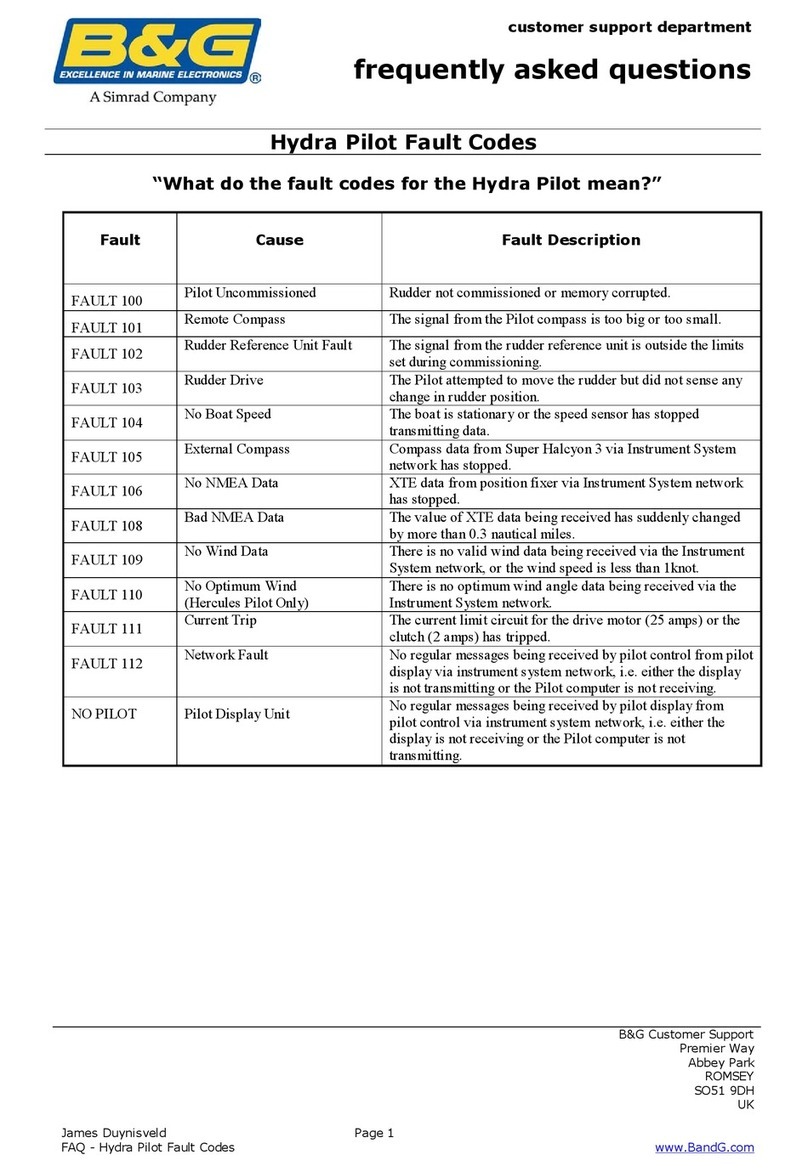
B&G HB-1000I User manual

h1000 pilot
installation
manual
HB-1000I
Issue: 0001

h1000 pilot index
Page 1
index
index 1
h1000 pilot display 4
description 4
siting the pilot head 4
mounting procedure 5
panel mounting 5
h1000 compass unit 6
description 6
siting the compass unit 6
mounting procedure 6
rudder reference unit (rru) 7
description 7
key points when installing the rru 7
linear feedback unit 11
rudder drive options 12
ram drive unit 12
description 12
hydraulic linear drives 12
hydraulic ram drive dimensions (T1-12V, T2-12V, T2-24V) 14
size 3 hydraulic ram drive dimensions, 24V 15
ram details 16
rose joint detail 16
mounting plate details 16
ram bolt detail 16
ram drive unit installation 17
key points on installation 17
layout of typical ram drive unit 18
ram mounted parallel to vessel’s centre-line 19
key points on installation 20
mounting a hydraulic linear ram on a vertical bulkhead 20
vertical bulkhead installation 21
splitting the ram drive unit 22
type 1 and type 2 units 22
type 3 units 22
hydraulic drive pumps 23
description 23
pump data 23
key points on installation 23
hydraulic drive pump dimensions 24
type 1 and 2 24
type 3 24
hydraulic drive pump installation 25

index h1000 pilot
Page 2
index
hydraulic drive pump installation examples 26
single station system example 26
dual station system example 26
dual station system with bypass example 27
dual station pressurisedsystem example 27
advanced control processor unit (acp) 28
description 28
siting the acp 28
mounting procedure 28
cable and connection information 29
emc compliance 29
general wiring notes 29
all rudder drives –heavy duty power cables 30
linear drives –clutch/valvecables 30
acp unit terminal details 30
wire colour coding and abbreviations 30
wiring connections 31
clutch voltage selection 31
acp dip switch location 32
h1000 and alarm connections 33
hand-held, mob and joystick 34
hydraulic ram drive connections 35
ram solenoid wiring details 36
hydraulic pump connections 37
continuous drive connections 38
direct paddle input connection 39
linear feedback connection 40
non-b&g paddle connection 41
gyro stabilized compass connection 42
furuno ad10 heading connection 43
optional accessories 44
hand-held controller 44
description 44
siting the hand-held unit 44
mounting procedure 44
man overboard button (mob) 45
description 45
siting the man overboard alarm button 45
mounting procedure 45
acp joystick 46
description 46
siting the joystick 46
mounting procedure 46
h1000 pilot index
Page 3
index
h1000 pilot calibration 47
pilot installation checklist 47
drive unit and steering system 47
linear hydraulic rams 47
size 3 ram installation checklist 47
hydraulic pumps 47
rotary drives 47
rudder reference unit installation 48
linear feedback unit installation 48
compass installation 48
electronics installation 48
speed calibration 49
calibrating the pilot 51
pilot calibration parameters 51
docksidecalibration 51
selecting the boat type 52
setting the rudder end stops 52
setting the port rudder stop 52
setting the starboard rudder stop 52
selecting the rudder drive type 52
hardovertime 53
waterline length 53
magnetic dip angle 54
magnetic dip angle compensation chart 54
joystickcontrol 54
seatrial calibration 55
engaging the h1000 pilot 56
setting the rudder midships position 56
boat lag 56
setting the boat lag value 57
boat lag value table 57
automatic rudder gain 57
checking the automatic rudder gain learning 57
manual rudder gain 58
rudder gain value table 58
trouble shooting 56
uncalibrated 56
no rudder position 56
no drive selected 57
no boat speed 57
no heading data 57
no nmea information 58
nmea data unstable 58
poor wind data 58
current trip limit 58
no pilot detected 59
pilot not steering a straight course 59

description/installation h1000 pilot
Page 4
h1000 pilot display
descriptiondescription
The h1000 pilot display is designed to be mounted above or below decks. The display head allows
control of the pilot and by installing multiple display heads, gives control at any station. It can be
connected to all other h1000 Instruments via the Fastnet2connectors to provide an integrated autopilot
and navigational system.
CautionCaution: It is essential that the pilot be calibrated before operation. Details are given in the
calibration section of this manual.
In an integrated system, boat speed is supplied from the h1000 Speed/Depth Interface and wind speed
and wind angle from the h1000 Wind Interface via Fastnet2. These allow the pilot to operate in the
Compass and Wind modes. When a CND orNMEA position fixer is connected to the system, Navigate
mode becomes available. NMEA data is connected to the Universal Interface and then broadcast
across Fastnet2and used by the pilot.
The display heads are supplied with a clip-in mounting bracket, which allows for easy installation.
Access from behind is not necessary to secure the unit in place. However to prevent theft or if removal
of the unit is not required, then locking studs and thumb-nuts are supplied to allow for permanent
fixing.
siting thsiting the pilot display heade pilot display head
All h1000 instruments are designed for mounting above or below decks. Select a display site that is:
•At a convenient position within easy reach and view of the helmsman.
•On a smooth and flat surface.
•At a safe distance of 100mm (4") from any compasses.
•Reasonably well protected from physical damage.
•Accessible from behind for fitting locking studs if required.

h1000 pilot description/installation
Page 5
mounting procedure
panel mounting
Ensure there is sufficient room behind the panel to accommodate the fixings and connections, and
using the template supplied, cut a hole in the panel in the desired position.
Fix the mounting bracket into the hole using the screws supplied.
Note: The sealing ring is fitted to the unit during manufacture, it purpose is to prevent moisture
penetration and reduce the effects of any vibration transmitted through the instrument panel.
Press the Pilot Displayfirmly into the mounting bracket; an audible ‘click’ will indicate that the case
is correctly located.
Secure the unit to the instrument panel by fitting the studs and thumbnuts supplied.
Caution: To avoid damaging the casing, fixing studs must only be tightened ‘finger-tight’.
Mounting
Bracket
Sealing Ring
(Fitted at Manufacture)
Pilot Display
Unit
Protective
Cover

description/installation h1000 pilot
Page 6
h1000 compass unit
description
The h1000 compass is an electronic fluxgate for use with all h1000 systems. The unit is housed in a
sealed casing constructed of high impact plastic. It is therefore suitable for on or below deck mounting.
If installed in a vessel with a steel or reinforced concrete hull it may be necessary to install the
compass unit outside the magnetic screening affect of the hull and super-structure.
Two Fastnet² connectors are provided at the base of the unit. These connectors allow connection to the
rest of the system for the supply of power and data.
siting the compass unit
Mount the compass upright on a flat vertical bulkhead where it will be:
•A safe distance from external magnetic interference:
3m (10ft) from VHF, RDF, loudspeakers, depth sounders, engines, or power cables carrying
heavy current.
•3m (10ft) from radar and SSB equipment.
•Externally mounted on steel vessels.
•Well protected from physical damage.
•Protected from water ingress (particularly bilge water).
•Optimum positioning: as low as possible to minimise effect of pitching and rolling of boat.
mounting procedure
•Secure the unit in the selected site using the non-magnetic self-tapping screws provided.
•Route the Fastnet2cable to the rest of the system avoiding other cables carrying heavy currents,
e.g. engine starter, trim-tabs, etc.
•Secure in place with cable clips or tie-wraps.
•Avoid bending the cable through a tight radius especially near the connector as this may damage
the wires inside the cable.

h1000 pilot description/installation
Page 7
rudder reference unit (rru)
description
The Rudder Reference Unit (rru) is a sealed, high specification potentiometer in a robust casing,
providing rudder position information to the pilot computer unit. The operating arm is constructed from
aluminium with three positions pre-drilled for the adjustable drag-link. The drag-linkhasball-jointsat
each end which connect the unit operating arm to the tiller arm or steering quadrant. The unit base has
four holes to allow for mounting. The unit is supplied with 10m (30ft) of 3-core screened cable.
key points when installing the rru
•General consideration must be given to the steering system and its geometry before starting the
RRU installation. Many factors must be contemplated for a practical solution. The information
given here is for guidance only, although where a maximum or a minimum value is given these
must be adhered to.
•Mount the rru on a flat surface next to the tiller arm or steering quadrant; construct a small
platform if necessary.
•Do not lengthen the drag-link arm as this can transmit excessive vibration loads to the rru and
will invalidate the warranty.
•The unit operating arm can be rotated through 360°; the mid-point of the rru travel is when the
operating arm is opposite the cable entry point.
•When the rudder is moved from hardover port to hardover starboard the rru arm should
swing through a minimum of 90°. This will ensure that there is sufficient voltage swing to the autopilot.

description/installation h1000 pilot
Page 8
rudder reference unit
Measure the voltage difference between the green and blue wires of the rru; there should be a
minimum of 1volt change from hardover to hardover.
Note: If there is less than a 1volt change the pilot will not commission.
•After installation check full movement of the steering system ensuring that there is no fouling
between the steering gear, rru parts and drive unit.
•Ensure that there is no backlash in the linkage between the rru and the steering gear, otherwise
incorrect operation of the autopilot will occur.
The example shown overleaf is a plan view of a typical system with a tiller arm and quadrant. When
viewed in elevation, the ram drive arm and rudder reference unit drag-link must not be more than ±9°
from horizontal. Ideally, all components should be horizontally aligned as this prevents excessive
stress during operation.

h1000 pilot description/installation
Page 9
rudder reference unit

description/installation h1000 pilot
Page 10
rudder reference unit
The RRU can be mounted in a variety of positions and orientations depending on the layout of the
steering system.
If the maximum rudder angle is less than 90°then the position of the RRU or the drag-link must be
adjusted so that the operating arm of the RRU swings through a minimum of 90.
1VMINIMUM
VARIATION
90°MINIMUM RRU ANGLE

h1000 pilot description/installation
Page 11
rudder reference unit
The rudder hardover angle should only be limited by the rudder stops, not the rru linkage or pilot drive
unit. Check that when hardover, the rru arm and drag-link do not form a straight line. If this occurs the
steering system could become damaged or jammed endangering the boat and crew.
This fault can easily be rectified, by adjusting the position of the RRU.
linear feedback unit
Where installation of the conventional rudder reference unit is difficult or physically impossible, a
linear feedback unit can be used. The linear feedback unit comprises of a tube approximately 23mm
(7/8 inch) in diameter and 324mm (12¾ inch) long. This assembly is clamped to the side of the linear
actuator using a special bracket kit. The linear feedback shaft is attached to the tiller bracket using
the pin supplied with all blue rams.
Note: This unit requires careful installation and alignment, which should be carried out by your
dealer or supplier. For electrical connection, refer to the wiring diagram detailed on
Page 35 of this manual.

description/installation h1000 pilot
Page 12
rudder drive options
ram drive unit
description
A hydraulic pump driven from the dc electric supply combines compact reversible pump and a
hydraulic cylinder assembly for use on boats without hydraulic steering systems. Three sizes of ram
drive units are available giving a wide range of thrust to suit all vessel types and sizes.
hydraulic linear drives
The Type 1 and Type 2 rams combine motor, pump and hydraulic cylinder as one unit, referred to as an
actuator. Type 3 rams are supplied split into a separate motor/pump unit, reservoir and hydraulic
cylinder, connected by 1m (3ft) hoses. The Type 3 motor/pump unit can be mounted on a vertical
bulkhead.
.
Note: Longer hoses for the Type 3 system are available, please contact your dealer.
Ram Drive Type RAM-T1-12V RAM-T2-12V RAM-T2-24V RAM-T3-24V
Motor Supply 12V dc 12V dc 24V dc 24V dc
Solenoid Valve
Supply 12V dc
1.25A (max) 12V dc
1.25A (max) 24V dc
1.25A (max) 24V dc
0.8A (max)
Peak Thrust 680 kg force
(1496 lbs force) 680 kg force
(1496 lbs force) 1062 kg force
(2342 lbs force)
Peak Current 20A @ 12V 25A @ 12V 25A @ 24V 17A @ 24V
Maximum
Stroke 254mm
(10") 254mm
(10") 254mm
(10”) 305mm
(12")
Full Bore
Annulus Area 1208mm2
(1.872"2)
1005mm2
(1.558”2)
1208mm2
(1.872"2)
1005mm2
(1.558"2)
1208mm2
(1.872"2)
1005mm2
(1.558"2)
1885mm2
(2.92"2)
1570mm2
(2.434"2)
Rod Diameter 16mm
(0.623”) 16mm
(0.623") 16mm
(0.623") 20mm
(0.623")
Tiller Arm for
70°Rudder 214mm
(8.4") 214mm
(8.4") 214mm
(8.4") 257mm
(10.16")
Maximum
Torque 1427 Nm
(12574 lb.ins) 1427 Nm
(12566 lb.ins) 1427 Nm
(12566 lb.ins) 2688 Nm
(23780 lb.ins)
Weight 7 kg
(15 lbs 6oz) 7 kg
(15 lbs 6oz) 7 kg
(15 lbs 6oz) 10.3 kg
(22lbs 11oz)
Helm to Helm
Time
Extend
Retract
15.7 sec
13.4 sec
(200kg force)
11.9 sec
10.2 sec
(200kg force)
11.9 sec
10.2 sec
(200kg force)
14.6 sec
12.6 sec
(200kg force)

h1000 pilot description/installation
Page 13
rudder drive options
The following table may be used to determine the steering system geometry for different maximum
rudder angles and ram type. The last three columns show the peak torque available (in Kgm),
amidships position and at the maximum rudder angle. The latter two are shownwiththemotorrunning
at 50% duty cycle.
RAM-T1-12V
Midstroke = 505.0mm
d = 73.3mm
½ Max
Rudder
Angle
Tiller Arm
mm Offset
mm Thrust
(peak Kgf) Torque at
amidships
(peak Kgf)
Torque at
amidships
(50% Kgm)
Torque
(at max°
50% Kgm)
abc
25 290 272 680 197 197 179
30 245 227 680 167 167 144
35 214 196 680 145 145 119
40 190 172 680 129 129 99
45 173 155 680 118 118 83
50 160 142 680 109 109 70
RAM-T2-12V, RAM-T2-24V
Midstroke = 505.0mm
d = 73.3mm
½ Max
Rudder
Angle
Tiller Arm
mm Offset
mm Thrust
(peak Kgf) Torque at
amidships
(peak Kgf)
Torque at
amidships
(50% Kgm)
Torque
(at max°
50% Kgm)
abc
25 290 272 680 197 128 116
30 245 227 680 167 108 94
35 214 196 680 145 95 77
40 190 172 680 129 84 64
45 173 155 680 118 77 53
50 160 142 680 109 71 45
RAM-T3-24V
Midstroke = 690.0mm
d = 51.0mm
½ Max
Rudder
Angle
Tiller Arm
mm Offset
mm Thrust
(peak Kgf) Torque at
amidships
(peak Kgf)
Torque at
amidships
(50% Kgm)
Torque
(at max°
50% Kgm)
abc
25 350 326 1062 372 372 337
30 295 271 1062 313 313 271
35 257 233 1062 273 273 223
40 230 206 1062 244 244 187
45 210 186 1062 223 223 157
50 193 169 1062 205 205 131

description/installation h1000 pilot
Page 14
hydraulic ram drive dimensions (T1-12V, T2-12V, T2-24V)

h1000 pilot description/installation
Page 15
size 3 hydraulic ram drive dimensions, 24V

description/installation h1000 pilot
Page 16
ram details

h1000 pilot description/installation
Page 17
ram drive unit installation
Note:General consideration must be given to the steering system and its geometry before starting
the installation. Many factors must be contemplated for a practical solution; theinformation
given here is for guidance only, although where a maximum or minimum value is given this
must be adhered to. It is essential that the unit be installed in a fully functional steering
system, with no backlash or stiffness when operating. Rectify any steering problems before
installation of the ram drive unit or the autopilot will not function correctly.
key points on installation
•Check that the steering gear is in good condition. Rectify any steering defects prior to installation
of the ram.
•The ram drive unit must be secured onto a flat, rigid base. It maybe necessary to construct a
platform section for the mounting plate. For angled rudderstocks, an angled platform section will
have to be constructed.
•All setting-up and aligning of the ram drive unit with the steering system should be carried out
with the rudder in the amidships position and the ram arm at the centre point of its travel.
•The angle between the ram arm and the tiller arm should be as shown in the following diagrams.
•The ram arm should ideally be at right angles to the rudderstock. The ball-jointontheendofthe
ram arm will allow a MAXIMUM of ±9°of vertical misalignment.
Caution: For Type 3 Ram Reservoir Installation, do not turn the black reservoir tap on or attempt to
move the piston rod until all of the following are completed:
•The base foot of the ram and pump has been bolted into position.
•The reservoir has been fixed to a bulkhead above the ram and pump.
•The sealed reservoir transit cap has been replaced by the breather cap supplied.
•The reservoir has been filled with the oil supplied.
When the checks listed above have been verified, the reservoir tap can be switched to the ‘‘ON’’ position
allowing the oil to flow between the reservoir and the pipe. (Tap “ON” position is in-linewiththepipe).

description/installation h1000 pilot
Page 18
layout of a typical ram drive unit
b=tillerarm
length
a=halfmaxrudderangle
d

h1000 pilot description/installation
Page 19
ram mounted parallel to vessel’s centre-line
Table of contents
Other B&G Marine Equipment manuals

B&G
B&G Triton Display User manual

B&G
B&G Zeus 3S User manual

B&G
B&G H5000 Pilot User manual

B&G
B&G Zeus3 Glass Helm User manual

B&G
B&G h1000 pilot User manual

B&G
B&G Zeus2 series User manual

B&G
B&G Triton Edge User manual

B&G
B&G H5000 Pilot User manual

B&G
B&G H5000 Pilot Use and care manual

B&G
B&G Zeus Touch User manual
Popular Marine Equipment manuals by other brands

COBHAM
COBHAM Sailor 500 FleetBroadband installation manual

Interphase
Interphase 20/20 Dual Operation manual

Furuno
Furuno NAVpilot 711C Operator's manual

Kongsberg
Kongsberg Simrad PX Door Adapter Starboard installation manual

Yanmar
Yanmar SD25 Operation manual

Thrane&Thrane
Thrane&Thrane Sailor 250 FleetBroadband installation manual