Tritech Merlin User manual

Merlin
0711-SOM-00001, Issue: 03 1 © Tritech International Ltd.
Merlin
Product Manual
0711-SOM-00001, Issue: 03

Merlin
0711-SOM-00001, Issue: 03 2 © Tritech International Ltd.
© Tritech International Ltd
The copyright in this document is the property of Tritech International Ltd. The document is supplied by Tritech International Ltd on
the understanding that it may not be copied, used, or disclosed to others except as authorised in writing by Tritech International Ltd.
Tritech International Ltd reserves the right to change, modify and update designs and specifications as part of their ongoing
product development programme.
All product names are trademarks of their respective companies.

Merlin
0711-SOM-00001, Issue: 03 3 © Tritech International Ltd.
Table of Contents
Help & Support ........................................................................................................... 4
Warning Symbols ........................................................................................................ 5
1. Introduction ............................................................................................................. 6
2. Specification ........................................................................................................... 7
3. Installation .............................................................................................................. 8
3.1. Mechanical ................................................................................................... 8
3.2. Water Hoses ................................................................................................ 8
3.3. Hydraulics .................................................................................................... 9
3.4. Retro Flush Valve and Jet Bypass Valve ..................................................... 11
3.5. Seal Compensator ...................................................................................... 12
4. Principles of Operation .......................................................................................... 13
4.1. Suction Operation ....................................................................................... 13
4.2. Jetting Operation ........................................................................................ 13
5. Maintenance ......................................................................................................... 14
5.1. Tools Required ........................................................................................... 14
5.2. Basic Procedures ....................................................................................... 14
5.3. Fitting Spacer to Retro Valve Actuator ......................................................... 15
6. Troubleshooting .................................................................................................... 21
A. Motor Protector Assembly Procedure ..................................................................... 22
B. Merlin Assembly ................................................................................................... 24
C. Merlin Actuator Spacer ......................................................................................... 32

Merlin
0711-SOM-00001, Issue: 03 4 © Tritech International Ltd.
Help & Support
First please read this manual thoroughly (particularly the Troubleshooting section, if present).
If a warranty is applicable, further details can be found in the Warranty Statement, 0080-
STF-00139, available upon request.
Tritech International Ltd can be contacted as follows:
Mail Tritech International Ltd
Peregrine Road
Westhill Business Park
Westhill, Aberdeenshire
AB32 6JL, UK
Telephone ++44(0)1224 744 111
Email [email protected]
Website www.moog.com/tritech
Prior to contacting Tritech International Ltd please ensure that the following is available:
1. The Serial Numbers of the product and any Tritech International Ltd equipment connected
directly or indirectly to it
2. Software or firmware revision numbers
3. A clear fault description
4. Details of any remedial action implemented
Contamination
If the product has been used in a contaminated or hazardous environment you
must de-contaminate the product and report any hazards prior to returning the
unit for repair. Under no circumstances should a product be returned that is
contaminated with radioactive material.
The name of the organisation which purchased the system is held on record at Tritech
International Ltd and details of new software or hardware packages will be announced at
regular intervals. This manual may not detail every aspect of operation and for the latest
revision of the manual please refer to www.moog.com/tritech
Tritech International Ltd can only undertake to provide software support of systems loaded
with the software in accordance with the instructions given in this manual. It is the customer's
responsibility to ensure the compatibility of any other package they choose to use.
Merlin
0711-SOM-00001, Issue: 03 5 © Tritech International Ltd.
Warning Symbols
Throughout this manual the following symbols may be used where applicable to denote any
particular hazards or areas which should be given special attention:
Note
This symbol highlights anything which would be of particular interest to the reader
or provides extra information outside of the current topic.
Important
When this is shown there is potential to cause harm to the device due to
static discharge. The components should not be handled without appropriate
protection to prevent such a discharge occurring.
Caution
This highlights areas where extra care is needed to ensure that certain delicate
components are not damaged.
Warning
DANGER OF INJURY TO SELF OR OTHERS
Where this symbol is present there is a serious risk of injury or loss of life. Care
should be taken to follow the instructions correctly and also conduct a separate
Risk Assessment prior to commencing work.

Merlin
0711-SOM-00001, Issue: 03 6 © Tritech International Ltd.
1. Introduction
The Merlin is an integrated eductor based excavation system which is designed to pump
mud, sand, gravel, drill cuttings or shale without risk of blockage.
A heavy-duty cylinder operates a valve to reverse the flow at the nozzle to eject any object
which may be causing an obstruction. A second cylinder operates a bypass valve to provide a
powerful direct jet to break up heavy and cohesive seabed mud and sand prior to excavation.
The pump may be configured to an intermediate position allowing combined use of suction
and jettings. Both the impeller and eductor have been optimised for use on Work-class ROVs.
Merlin
0711-SOM-00001, Issue: 03 7 © Tritech International Ltd.
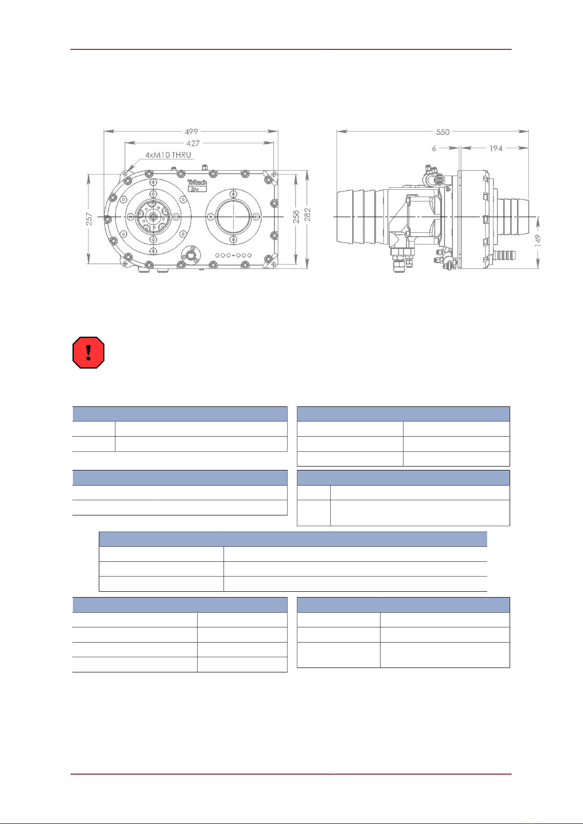
2. Specification
Not to scale, dimensions in mm.
Warning
Never use the same size fitting for pressure hoses and the case drain. If this is done there
is significant risk of incorrect hook-up which will lead to pressure being applied to the motor
casing and could result in an explosion and personal injury.
Hydraulic Motor Input
Pressure 170 to 250 Bar (2450 to 3600 psi)
Flow 65 to 110 litres/min (17 to 29 USgpm)
Hydraulic Fittings
Motor A & B No. 12 JIC male
Motor case drain No. 6 JIC male
Actuator Connection No. 4 JIC male
Actuator
Min. pressure 120 Bar (1740 psi)
Max. pressure 240 Bar (3480 psi)
Check Valve
Norm. Tritech Volvo Protector Assembly
Alt. Integrated Hydraulics FPR-1/22-0.5 (cracking
pressure 0.5 bar)
Output
Typical output jetting Up to 600 litres/min @ 8 Bar (160 USgpm @ 115 psi)
Typical output suction 2000 - 4000 litres/min (500 - 1000 USgpm)
Typical solids removal 10 - 40 tonnes/hour (350 - 1500 lb/min)
Nozzle Dimensions
Jetting 25.4mm (1")
Discharge 155mm (6")
Suction 104mm (4")
Clean water inlet 104mm (4")
Weight and Materials
Weight in air 40kg (90lb)
Weight in water 17kg (38lb)
Materials Stainless steel, Nylacast,
UHMWPE
Merlin
0711-SOM-00001, Issue: 03 8 © Tritech International Ltd.
3. Installation
Warning
Do not power the Merlin pump or hydraulic valve actuators until all hoses are
properly connected.
If powering or testing on deck it is important to ensure that all appropriate safety
measures are in place to prevent injury.
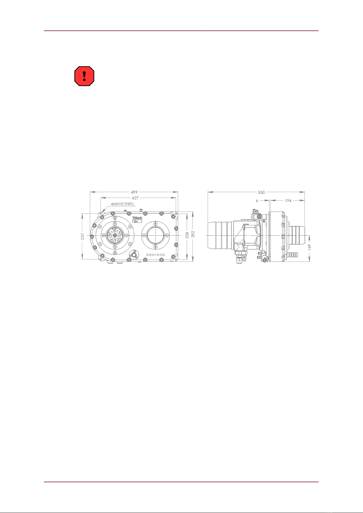
3.1. Mechanical
The pump may be mounted in any orientation on the vehicle. There are four mounting points
with 10mm clearance through holes
Not to scale, dimensions in mm.
the pump should not be mounted using the motor or hose nozzles as attachment points.
Case bolts should not be used.
3.2. Water Hoses
Hose Types
For correct hose sizes refer to Chapter 2, Specification.
The recommended hose type is: heavy duty nylon spiral reinforced.
This hose type is usually semi-transparent which assists visual inspection for damage and
blockages. Since it is all plastic it is light in water.
Both suction and discharge hoses should have a smooth internal bore with spiral
reinforcement.
Layflat style hoses are not recommended for discharge.

Installation Merlin
0711-SOM-00001, Issue: 03 9 © Tritech International Ltd.
Fittings
Use standard heavy-duty worm drive clips. Use of heavy-duty two bolt clamps will result in
damage to the hose connections on the pump unit.
Clean Suction Intake Screen
It is recommended that a Tritech International Ltd supplied suction strainer is used with the
pump. If using another strainer it must meet the following specifications:
• Maximum hole size: square mesh of 4mm aperture or circular perforations of 6mm
diameter.
• Minimum total free flow area: 0.025m²
The pump should not be operated in any circumstances without a suction screen.
Dredge Suction Nozzle
Suction nozzles should be designed with a nozzle cross-section area of approximately
80000mm²
Smaller nozzles may be used but material removal rates will be reduced. Larger nozzles are
of no benefit and will reduce performance.
A nozzle guard should be fitted that will pass a maximum of a 60mm diameter sphere or
50mm sided cube. The pump can pass single objects of a larger size, but if it takes in a
stream of objects then blockages can occur.
Jet Nozzle
The recommended sizes are 12 to 18mm diameter or an equivalent area.
The optimum size will need to be determined by trial because the water output from the power
pump will vary depending on the oil pressure and flow available from the ROV hydraulic
system.
3.3. Hydraulics
Oil
The pump should be operated using a premium grade mineral based hydraulic oil of ISO
VG 22 to 23
Filtration
The hydraulic system filtration must be to a minimum of 10μm absolute standard. A 10μm
nominal standard is regarded as inadequate.

Installation Merlin
0711-SOM-00001, Issue: 03 10 © Tritech International Ltd.
The recommended filtration is UN elements produced by Pall Industrial Hydraulics Ltd. or
equivalent products.
Hook-up
Figure 3.1. Hydraulic Hook-up Orientation
The pump is configured for correct rotation when the hydraulic supply is connected to the "A"
port of the Volvo motor and the return line to the "B" port.
Figure 3.2. Motor viewed when fitted to Merlin with hydraulic fittings downwards

Installation Merlin
0711-SOM-00001, Issue: 03 11 © Tritech International Ltd.
The drain connection from the motor back to the tank is required to be a minimum of ⅜
inch bore. The drain line should return straight to the tank without restriction. It is possible to
connect the drain line back to a larger bore drain manifold, which has been correctly sized
to accommodate all drains attached to it.
Warning
The drain line should not be connected to any return flow lines.
Warning
Self-sealing quick disconnect connectors should not be used on the drain line.
Such connectors, if incorrectly fitted, may result in pressurisation of the motor
casing which could fail explosively under pressure resulting in significant risk of
personal injury.
Required Hydraulic Flow
For the Volvo F11-19 motor the vehicle hydraulic system should be capable of supplying a
flow rates and pressure detailed in Chapter 2, Specification.
Achieving the required flow in an unloaded condition is no guarantee that the supply can
actually be met in working conditions.
It is recommended that the installation be checked using a hydraulic flow meter equipped
with a loading valve which can simulate the motor running under load.
In order to avoid pressure losses a minimum of ½ inch bore pipes or hoses are used on the
flow and return lines (¾ inch or larger is recommended).
Warning
Under no circumstances should the flow be allowed to exceed the 25 litres per
minute (while testing in air).
Exceeding this pressure when operating in air (when there is no back-pressure
on the pump) may cause a catastrophic failure of the pump and result in personal
injury.
3.4. Retro Flush Valve and Jet Bypass Valve
To independent controls are required, one for the jetting actuator and one for the retro valve.
The actuators can be connected to any standard three-position 4-way solenoid valve. Pilot
operated check valves is preferred but a closed centre spool valve is adequate. If either
actuator is not used then they must be filled with oil and securely capped. This is particularly
important for the jet bypass valve, which could easily be pulled open severely reducing
efficiency.
The supply pressure for reliable operation is 120 bar.
The actuator connection fittings are: No. 4 JIC male
The jet valve should be powered shut when jetting is not required.

Installation Merlin
0711-SOM-00001, Issue: 03 12 © Tritech International Ltd.
3.5. Seal Compensator
The Merlin has a separately compensated seal void which is grease filled and has its own
miniature compensator.
On installation the compensator level should be checked. The stem has an indicator groove
showing when it is full. If necessary gently apply grease via the grease nipple provided until
the groove just shows or the grease is expelled from the overflow.
Caution
Pump the grease very slowly to avoid building up excessive pressure in front of
the motor face.

Merlin
0711-SOM-00001, Issue: 03 13 © Tritech International Ltd.
4. Principles of Operation
4.1. Suction Operation
The Merlin pump is based on the principles of the annular eductor pump. It has a monoblock
configuration in which the eductor pump and power pump are contained within a common
body.
The power for the eductor section of the pump is provided by a stream of clean water driven
by the centrifugal impeller section.
Clean water is drawn into the inlet, passes through the impeller of the power pump and is
then injected into the main suction stream via the annular eductor nozzle.
The main suction stream can convey heavy contamination of sand, mud, gravel and drilling
debris.
The pump has a retro flush valve just behind the eductor. When this is closed (operating
cylinder extended) the power fluid is then directed to the suction nozzle. This feature can be
used to clear a blocked suction nozzle or to complete a deburial operation by removing the
sand and mud from around an object.
The optimum performance will be obtained with the nozzle pushed deep into the debris and
agitated gently. Where a great deal of debris is encountered it will be necessary to keep
withdrawing the nozzle.
4.2. Jetting Operation
The body of the pump contains a jetting valve. The purpose of the valve is to provide water to
the jetting outlet. The valve may be configured to maintain suction during jetting operations.
For normal dredging operations the jet valve should be kept shut.
Note
The Merlin can be setup to restrict flow through the jetting valve. To implement
this place the M8 x 16 SKT CAP (item 9) in one of the three holes in the housing
mounting plate (item 1 - see Appendix B, Merlin Assembly).
• Hole 1 gives : ‘low jetting, high flow’
• Hole 2 gives : ‘medium jetting, medium flow’
• Hole 3 gives : ‘high jetting, low flow’

Merlin
0711-SOM-00001, Issue: 03 14 © Tritech International Ltd.
5. Maintenance
Warning
Do not power the pump or hydraulic valve actuators until all hoses are properly
connected to the pump.
There is a serious risk of injury to fingers if inserted into either the power water
intake or the pump delivery port.
If undertaking any testing operations suitable guards and other safety measures
must be in place.
5.1. Tools Required
The following tools are required to work on the pump:
• 22mm open ended spanner
• 13mm open ended spanner
• 18m ring spanner (for actuator stripdown)
• 10mm Allen key
• 8mm Allen key
• 6mm Allen key
• 5mm Allen key
• 2.5mm Allen key
• Dead blow hammer
• Loctite - "Studlock" for reassembly
For detailed assembly procedures refer to Appendix B, Merlin Assembly.
5.2. Basic Procedures
Hydraulic Motor Shaft Seals
The pumps are fitted with either an 'H' (red) or 'V' (brown) type seal. The type V is the standard
seal and is high pressure, high temperature.
Replacement of seals with anything other than a genuine seal (or Tritech International Ltd
supplied seal) will invalidate the warranty.
Pre-dive
Visual check for external damage.

Maintenance Merlin
0711-SOM-00001, Issue: 03 15 © Tritech International Ltd.
Check hoses are secure.
Check mountings are secure.
Check clean water suction strainer is in place and clear.
Check the mini compensator for the seal housing is extended. If not apply one or two strokes
with a grease gun until the compensator relieves.
Storage
Note
If the vehicle will be inactive for more than 48 hours run a a fresh water hose into
the clean water suction strainer for a few minutes and then spin the hydraulic
motor for about 15 seconds (taking care not to over-speed).
If the pump is removed from the vehicle, then the hydraulic ports should be blanked off with
metal caps and the unit washed out with fresh water.
Leave the actuator valves in their retracted position.
Visually inspect the leading edges of the power pump impeller for damage and erosion.
Up to four blades may have leading edge damage of 5mm width and 4mm depth before
replacement becomes essential.
If the majority of leading edges are eroded more than 3.5mm back from the bore of the inlet
nozzle then consideration should be give to replacing the impeller.
5.3. Fitting Spacer to Retro Valve Actuator
Over the lifetime of the Merlin Pump wear to the Retro Valve Core may cause the actuator
that drives it to go into geometric lock.
This procedure explains the fitting of Merlin Actuator Spacer (see Appendix C, Merlin Actuator
Spacer) to allow continued operation of the Merlin Pump.

Maintenance Merlin
0711-SOM-00001, Issue: 03 16 © Tritech International Ltd.
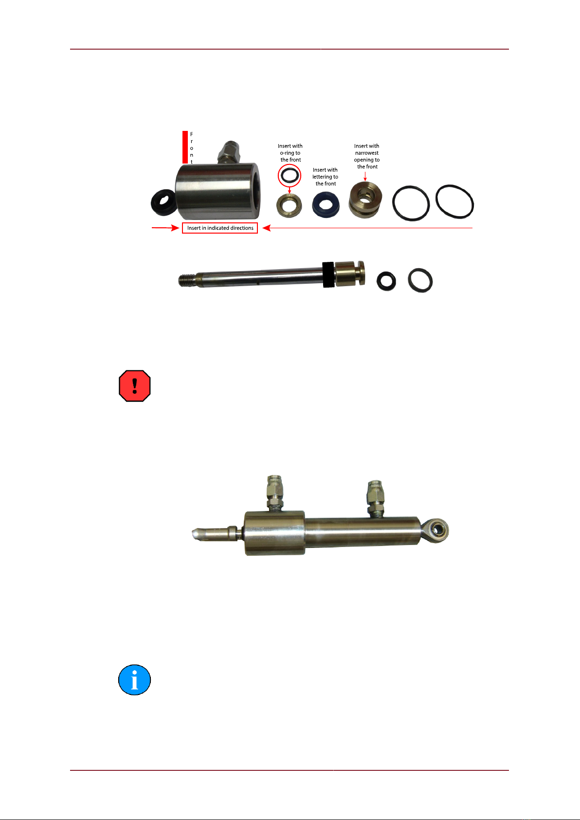
Actuator Parts
Item
number Description Quantity
1 Wiper Seal 1
2 Front Gland Insert Seal 1
3 Front Gland Insert Shaft Seal 1
4 Front Gland Seal 1
5 Rear Gland Seal 1
6 Shaft and Piston Assembly (Does not include item 7) 1
7 Stroke Spacer (for Retro Valve movement reduction) 1
8 Piston Seal 1
9 Piston Glide Ring 1
Maintenance Merlin
0711-SOM-00001, Issue: 03 17 © Tritech International Ltd.
Part Installation Overview
This is a brief overview of how the parts are assembled
Spacer Installation Method
Warning
Safety Eyewear should be work when carrying out this works as well as
appropiate hand protection.
Below is a new style actuator that is found on the Superzip, Merlin and newer Anchozip 10
pumps.
The procedure to disasemble the unit is as follows
• Remove the spherical bearing from the rod end. This can be done by extending the rod
and holding it tight in a vice. From there you can put a screwdriver through the rod end
spherical bearing and turn anti-clockwise. Once loosened it can be run off by hand.
Note
Soft or aluminium jaws should be used to prevent damage to the chrome shaft.
The shaft is a sealing face and should be treated as such.

Maintenance Merlin
0711-SOM-00001, Issue: 03 18 © Tritech International Ltd.
1
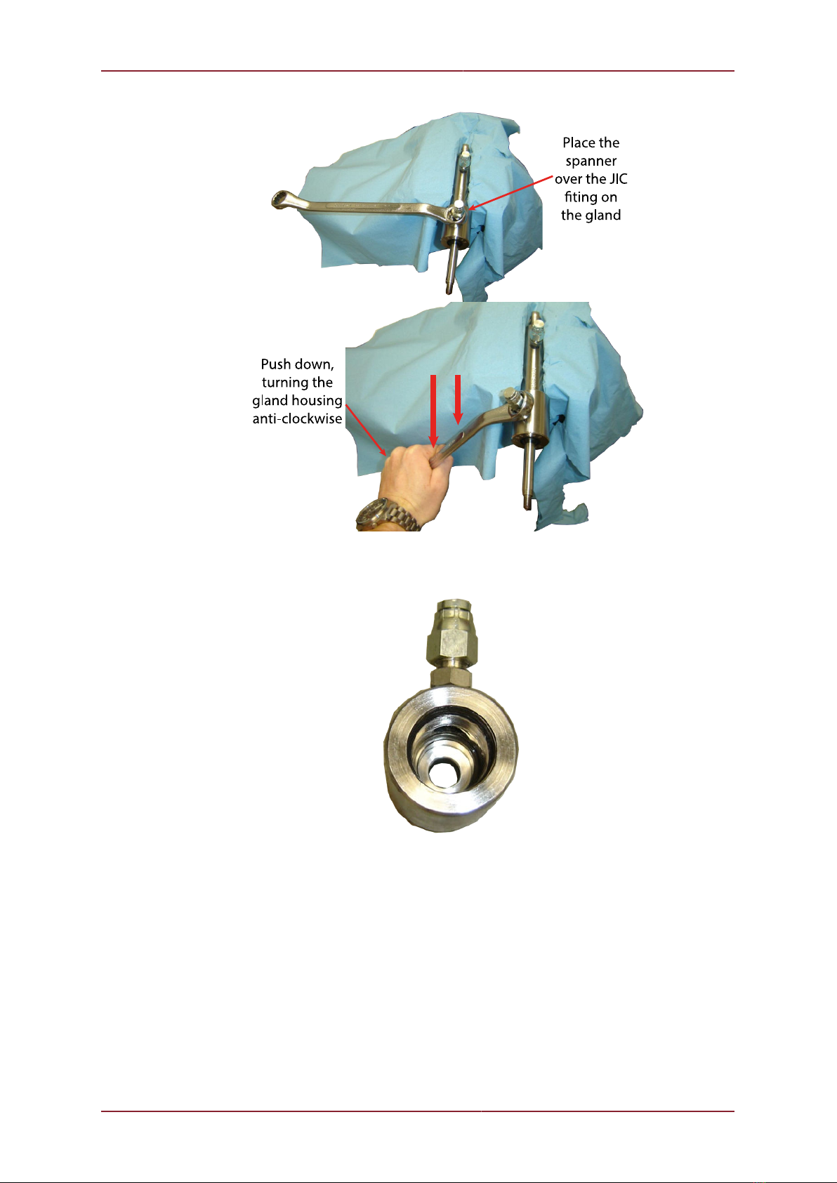
• Now the rod end bearing is off you can completely remove the top of the body. To do this,
hold the cylinder body in the vice.
• Then find a ring spanner and fit over the JIC fitting on the gland housing as below, leave
the cap on to protect the threads and increase the purchase (in this example the spanner is
18mm). Then pushing the spanner down (anti-clockwise) the whole gland housing will turn.
Maintenance Merlin
0711-SOM-00001, Issue: 03 19 © Tritech International Ltd.
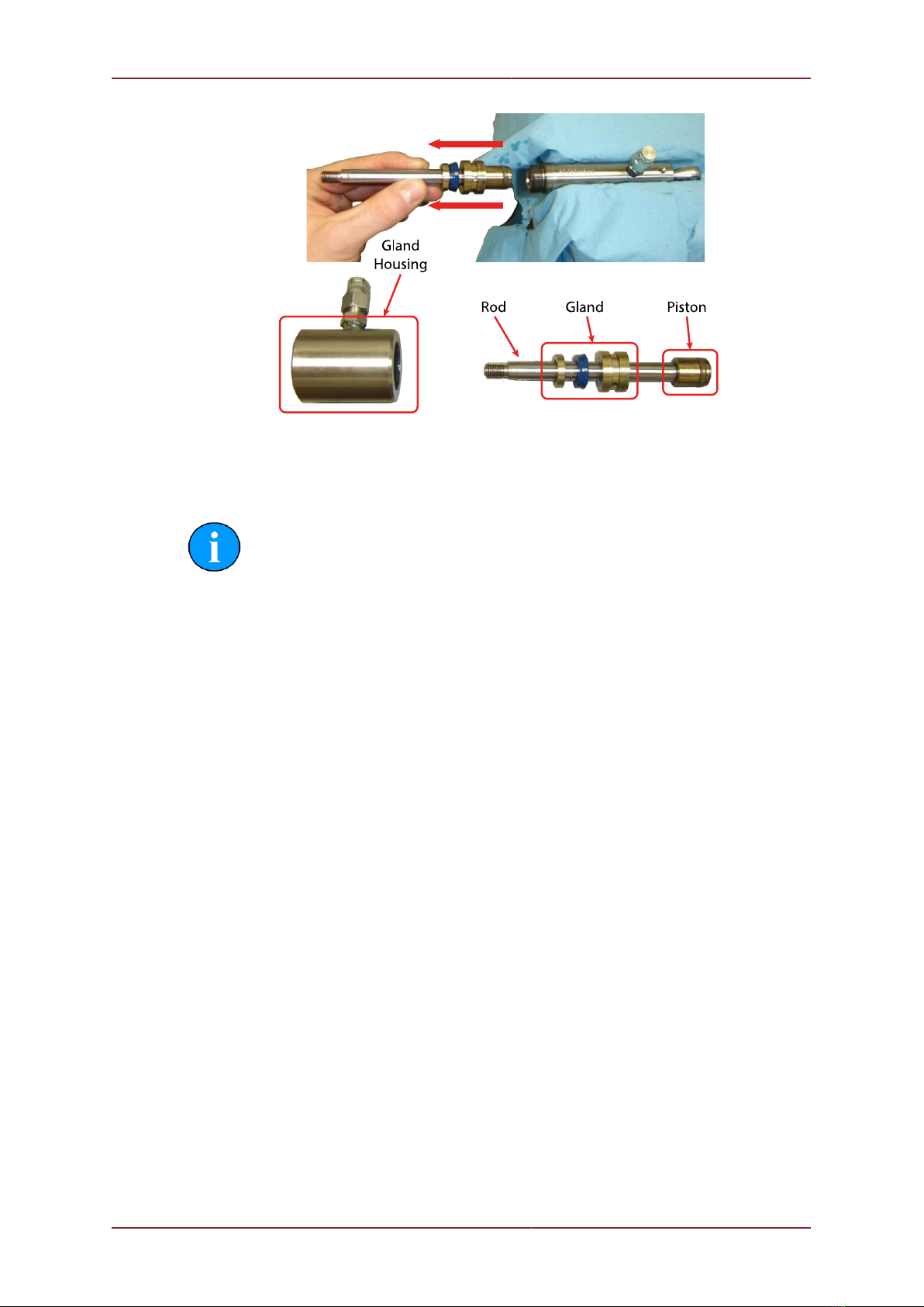
• You will then have the gland housing in your hand. (see below)
• The rod will then pull out taking the gland and the piston out with it. You may need to take
off the hydralic cap on the body to allow the piston to be removed.
Maintenance Merlin
0711-SOM-00001, Issue: 03 20 © Tritech International Ltd.
Assembly is the opposite of this procedure. Loctite should be used where the spherical
bearing is attached the the rod.
Note
If you are fitting the spacer to the actuator it would be prudent to label the actuator
as modified to prevent possible issues if the actuator is used for another function.
Table of contents
Other Tritech Water Pump manuals

Popular Water Pump manuals by other brands

Enerpac
Enerpac ZC Series instruction sheet

SKF
SKF Lincoln FlowMaster II User and maintenance instructions

EINHELL
EINHELL RHW 1300 Niro operating instructions

Whale
Whale Supersub Series Installation guides

Westmoor
Westmoor CONDE SDS Series owner's manual

Bühler technologies
Bühler technologies CPsingle X1 Installation and operation instructions

Aseko
Aseko PP60 user manual

Davey
Davey SJ35-04 Installation & operating instructions

Krautzberger
Krautzberger MP-520 operating instructions

Graco
Graco Husky 515 series Instructions-parts list

Goulds Pumps
Goulds Pumps VIT Installation, operation and maintenance instructions

Oase
Oase NEPTUN 600 operating instructions


