Tritech SuperZip User manual

SuperZip
SuperZip
Product Manual
0711-SOM-00003, Issue: 05

SuperZip
0711-SOM-00003, Issue: 05 2 © Tritech International Ltd.
© Tritech International Ltd
The copyright in this document is the property of Tritech International Ltd. The document is supplied by Tritech International Ltd on
the understanding that it may not be copied, used, or disclosed to others except as authorised in writing by Tritech International Ltd.
Tritech International Ltd reserves the right to change, modify and update designs and specifications as part of their ongoing
product development programme.
All product names are trademarks of their respective companies.

SuperZip
0711-SOM-00003, Issue: 05 3 © Tritech International Ltd.
Table of Contents
Help & Support ............................................................................................ 4
Warning Symbols ........................................................................................ 5
1. Introduction .............................................................................................. 6
2. Specification ............................................................................................ 7
3. Installation ............................................................................................... 8
3.1. Mounting ....................................................................................... 8
3.2. Water Hoses ................................................................................. 9
3.3. Hydraulics ................................................................................... 10
3.4. Seal Compensator ...................................................................... 12
4. Operating Principles .............................................................................. 13
4.1. Suction ........................................................................................ 13
4.2. Jetting .......................................................................................... 14
4.3. Testing in Air .............................................................................. 14
5. Maintenance .......................................................................................... 15
5.1. General Guidelines ..................................................................... 15
5.2. Basic Procedures ........................................................................ 15
5.3. Dismantling ................................................................................. 17
5.4. Re-assembly ............................................................................... 18
6. Troubleshooting ..................................................................................... 23
A. Motor Protector Assembly Procedure .................................................. 24
B. Parts List and Exploded Diagram ........................................................ 26

SuperZip
0711-SOM-00003, Issue: 05 4 © Tritech International Ltd.
Help & Support
First please read this manual thoroughly (particularly the Troubleshooting
section, if present). If a warranty is applicable, further details can be found in
a Warranty Statement at the end of the manual.
Tritech International Ltd can be contacted as follows:
Mail
Telephone
Email
Website
Tritech International Ltd
Peregrine Road
Westhill Business Park
Westhill, Aberdeenshire
AB32 6JL, UK
+44 (0)1224 744111
www.tritech.co.uk
Prior to contacting Tritech International Ltd please ensure that the following
is available:
1. The Serial Numbers of the product and any Tritech International Ltd equipment connected
directly or indirectly to it.
2. Software or firmware revision numbers.
3. A clear fault description.
4. Details of any remedial action implemented.
Contamination
If the product has been used in a contaminated or hazardous
environment you must de-contaminate the product and report
any hazards prior to returning the unit for repair. Under no
circumstances should a product be returned that is contaminated
with radioactive material.
The name of the organisation which purchased the system is held on record
at Tritech International Ltd and details of new software or hardware packages
will be announced at regular intervals. This manual may not detail every
aspect of operation and for the latest revision of the manual please refer to
www.tritech.co.uk
Tritech International Ltd can only undertake to provide software support of
systems loaded with the software in accordance with the instructions given in
this manual. It is the customer's responsibility to ensure the compatibility of
any other package they choose to use.
SuperZip
0711-SOM-00003, Issue: 05 5 © Tritech International Ltd.
Warning Symbols
Throughout this manual the following symbols may be used where applicable
to denote any particular hazards or areas which should be given special
attention:
Note
This symbol highlights anything which would be of particular
interest to the reader or provides extra information outside of the
current topic.
Important
When this is shown there is potential to cause harm to the
device due to static discharge. The components should not be
handled without appropriate protection to prevent such a discharge
occurring.
Caution
This highlights areas where extra care is needed to ensure that
certain delicate components are not damaged.
Warning
DANGER OF INJURY TO SELF OR OTHERS
Where this symbol is present there is a serious risk of injury or
loss of life. Care should be taken to follow the instructions correctly
and also conduct a separate Risk Assessment prior to commencing
work.

SuperZip
0711-SOM-00003, Issue: 05 6 © Tritech International Ltd.
1. Introduction
The SuperZip is a development from the Tritech International Ltd Zip Pump
and ZipJet range of products.
The integrated eductor based excavation system is designed to pump mud,
sand, gravel, drill cuttings and shale without the risk of blockage. A heavy
duty cylinder reverses the flow at the nozzle to eject any object which may
be causing and obstruction. A second cylinder operates a diverter valve to
provide a powerful direct jet to break up heavy and cohesive seabed mud and
sand prior to excavation.
Key features include:
• Separately compensated seal void to minimise ROV hydraulic oil
contamination
• Easy seal change and maintenance
• Lift handle and stabiliser foot
• Suction and jetting nozzles aligned
• Optional feed water filter
• Optional integrated suction and jetting nozzles
• Modular pump core to simplify maintenance
SuperZip
0711-SOM-00003, Issue: 05 7 © Tritech International Ltd.
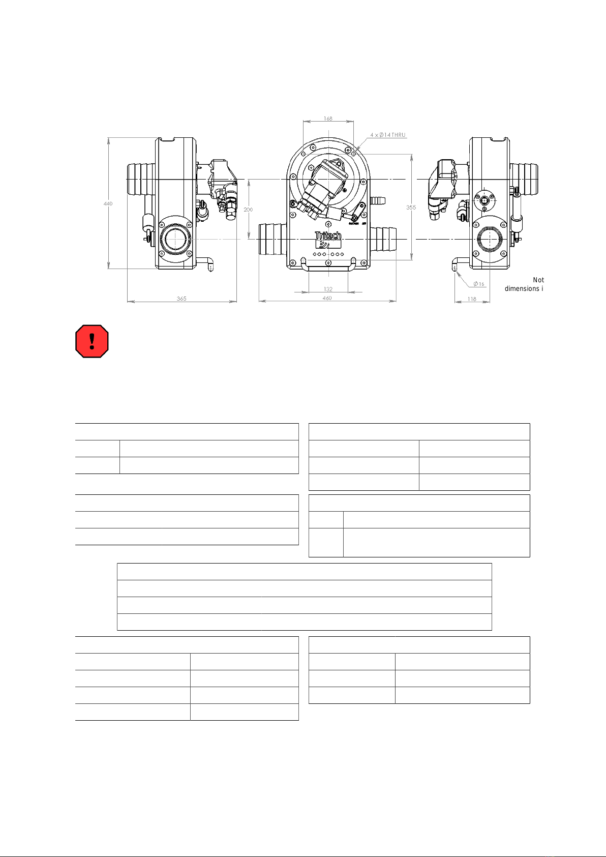
2. Specification
Not to scale,
dimensions in mm.
Warning
Never use the same size fitting for pressure hoses and the case drain. If
this is done there is significant risk of incorrect hook-up which will lead to
pressure being applied to the motor casing and could result in an explosion
and personal injury.
Hydraulic Motor Input
Pressure 150 to 220 Bar (2200 to 3200 psi)
Flow 40 to 60 litres/min (11 to 16 USgpm)
Hydraulic Fittings
Motor A & B No. 12 JIC male
Motor case drain No. 6 JIC male
Actuator Connection No. 4 JIC male
Actuator
Min. pressure 110 Bar (1595 psi)
Max. pressure 240 Bar (3480 psi)
Check Valve
Norm. Tritech Volvo Protector Assembly
Alt. Integrated Hydraulics FPR-1/22-0.5
(cracking pressure 0.5 bar)
Output
Jetting performance 1000 litre/min @ 2 Bar (270 USgpm)
Suction flow 500 - 1000 litres/min (135 to 270 USgpm)
Solids removal rate 5 - 10 tonnes/hour (184 - 368 lb/min)
Nozzle Dimensions
Jetting 25.4mm (1")
Discharge 104mm (4")
Suction 77.3mm (3")
Clean Water Inlet 104mm (4")
Weight and Materials
Weight in air 25kg (55lb)
Weight in water 11kg (24lb)
Materials Nylacast, UHMWPE

SuperZip
0711-SOM-00003, Issue: 05 8 © Tritech International Ltd.
3. Installation
Warning
Do not power the pump or hydraulic valve actuators until all hoses
are properly connected to the pump.
There is a serious risk of injury to fingers if inserted into either the
power water intake or the pump delivery port.
If undertaking any testing operations suitable guards and other
safety measures must be in place.
3.1. Mounting
The pump may be mounted in any orientation on the vehicle. There are
four mounting holes each with 12mm diameter clearance. Two of these are
occupied by the stabiliser foot, which may either be removed or used itself as
a mounting. If desired a second stabiliser bar may be fitted in the alternative
hole set
The pump should not be mounted using the motor or hose nozzles as
attachment points.
Figure 3.1. Mounting Holes

Installation SuperZip
0711-SOM-00003, Issue: 05 9 © Tritech International Ltd.
3.2. Water Hoses
Hose Types
Note
The recommended hose type is the Kanaline AW/Hydrasun
Arizona
Kanaline AW hoses have plastic reinforcement and a semi-transparent wall
which assists in visual inspection for damage or blockages. Alternative makes
of suction and discharge hose may be used provided that they have a smooth
internal bore.
Any crush resistant PVC coil strengthened hose may be used if the
recommended hoses are not available.
Lay-flat style hoses are not recommended for discharge.
Fittings
Use standard Kanaline fittings or heavy-duty worm drive clips. Use of heavy-
duty two bolt clamps will result in damage to the hose connections on the
pump unit.
Clean Suction Intake Screen
It is recommended that a Tritech International Ltd supplied suction strainer
is used with the pump. If using another strainer it must meet the following
specifications:
• Maximum hole size: square mesh of 40mm aperture or circular perforations
of 60mm diameter.
• Minimum total free flow area: 0.016m²
The pump should not be operated in any circumstances without a suction
screen.
Dredge Suction Nozzle
Suction nozzles should be designed with a nozzle cross-section area of
approximately 40cm²
Smaller nozzles may be used but material removal rates will be reduced.
Larger nozzles are of no benefit and will reduce performance.
Installation SuperZip
0711-SOM-00003, Issue: 05 10 © Tritech International Ltd.
A nozzle guard should be fitted that will pass a maximum of a 40mm diameter
sphere or 35mm sided cube. The pump can pass single objects of a larger
size, but if it takes in a stream of objects then blockages can occur.
Jet Nozzle
The recommended sizes are 14 to 19mm diameter or an equivalent area.
The optimum size will need to be determined by trial because the water
output from the power pump will vary depending on the oil pressure and flow
available from the ROV hydraulic system.
3.3. Hydraulics
Oil
The pump should be operated using a premium grade mineral based
hydraulic oil of ISO VG 22 to 32
Filtration
The hydraulic system filtration must be to a minimum of 10μm absolute
standard. A 10μm nominal standard is regarded as inadequate.
The recommended filtration is UN elements produced by Pall Industrial
Hydraulics Ltd. or equivalent products.
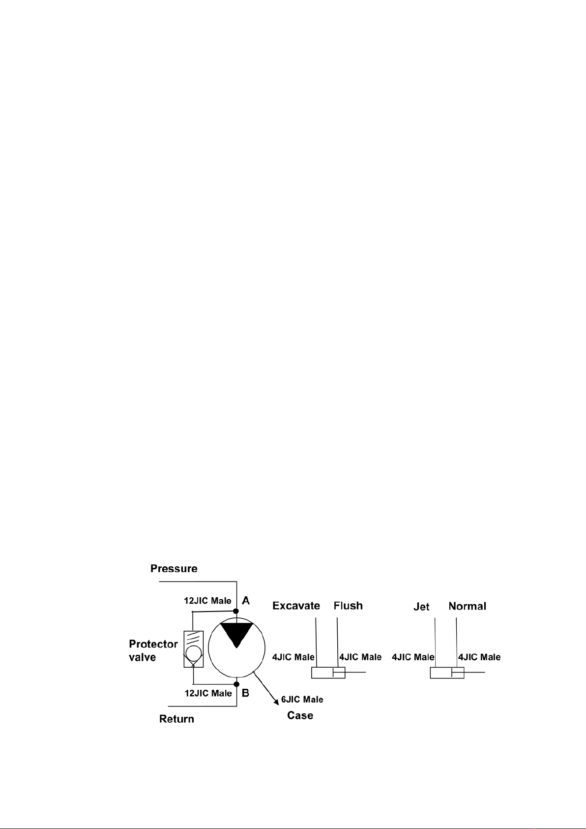
Hook-up
Figure 3.2. Hydraulic Hook-up Orientation

Installation SuperZip
0711-SOM-00003, Issue: 05 11 © Tritech International Ltd.
The pump is configured for correct rotation when the hydraulic supply is
connected to the "A" port of the Volvo motor and the return line to the "B" port.
Figure 3.3. Motor viewed when fitted to SuperZip with hydraulic fittings
downwards
The drain connection from the motor back to the tank is required to be a
minimum of ⅜ inch bore. The drain line should return straight to the tank
without restriction. It is possible to connect the drain line back to a larger
bore drain manifold, which has been correctly sized to accomodate all drains
attached to it.
The drain line should not be connected to any return flow lines.
Warning
Self-sealing quick disconnect connectors should not be used on
the drain line. Such connectors, if incorrectly fitted, may result
in pressurisation of the motor casing which could fail explosively
under pressure resulting in significant risk of personal injury.

Installation SuperZip
0711-SOM-00003, Issue: 05 12 © Tritech International Ltd.
Required Hydraulic Flow
For the Volvo F11-10 motor the vehicle hydraulic system should be capable
of supplying a flow rates and pressure detailed in Chapter 2, Specification.
Achieving the required flow in an unloaded condition is no guarantee that the
supply can actually be met in working conditions.
It is recommended that the installation be checked using a hydraulic flow
meter equipped with a loading valve which can simulate the motor running
under load.
In order to avoid pressure losses a minimum of ½ inch bore pipes or hoses
are used on the flow and return lines ¾ inch or larger is recommended).
3.4. Seal Compensator
The SuperZip has a separately compensated seal void which is grease filled
and has its own miniature compensator.
On installation the compensator level should be checked. The stem has an
indicator groove showing when it is full. If necessary gently apply grease
via the grease nipple provided until the groove just shows or the grease is
expelled from the overflow.
Caution
Pump the grease very slowly to avoid building up excessive
pressure in front of the motor face.

SuperZip
0711-SOM-00003, Issue: 05 13 © Tritech International Ltd.
4. Operating Principles
4.1. Suction
The SuperZip pump is based on the principles of the annular eductor pump. It
has a monoblock configuration and common body within which the educator
pump and power pump are contained.
The power for the eductor section of the pump is provided by a stream of
clean water driven by the centrifugal impeller.
Clean water is drawn into the inlet, passes through the impeller of the power
pump and is then injected into the main suction stream via the annular eductor
nozzle.
Figure 4.1. SuperZip Flow Diagram
The main suction stream can contain a heavy concentration of sand, mud,
gravel and drilling debris. The pump has a retro flush valve just behind the
eductor and when this is closed (operating cylinder extended) the power fluid

Operating Principles SuperZip
0711-SOM-00003, Issue: 05 14 © Tritech International Ltd.
is then directed to the suction nozzle. This feature can be used to clear a
blocked suction nozzle or to complete a deburial operation by blowing away
the last sand and mud from around an object.
The optimum performance will be obtained with the nozzle pushed deep into
the debris and agitated gently. Where a large amount of debris is encountered
it will be necessary to keep withdrawing the nozzle.
4.2. Jetting
The body of the pump contains a diverter vane. The purpose of the vane is to
switch the flow of the power pump water between the suction educator and
the jetting outlet.
The diverter should be operated fully in one direction or the other. Attempting
to share the flow between the eductor and the jet nozzle by using a
mid position will result in poor performance from both. The diverter is set
for suction when the cylinder is retracted and for jetting with the cylinder
extended.
4.3. Testing in Air
Warning
Under no circumstances must the flow be allowed to exceed 70
litres per minute when testing in air.
There is no back pressure on the impeller to control its speed and many
vehicle hydraulic systems are capable of higher deliveries when there are no
thrusters running. Motor over-speed can cause a catastrophic failure
To avoid excessive wear and the possibility of damaging the impeller and
body, the unit should not be run for extended periods out of the water (no
more than about 30 seconds). This is especially true when the unit is new.
Absence of water around the plastic removes the natural cooling mechanism
and may result in the moving parts becoming misshapen due to the heat.

SuperZip
0711-SOM-00003, Issue: 05 15 © Tritech International Ltd.
5. Maintenance
5.1. General Guidelines
Warning
Do not power the pump or hydraulic valve actuators until all hoses
are properly connected to the pump.
There is a serious risk of injury to fingers if inserted into either the
power water intake or the pump delivery port.
If undertaking any testing operations suitable guards and other
safety measures must be in place.
The pump is designed for low maintenance operation. The main materials are
stainless steel and wear resistant polymer plastics.
The only internal moving parts that may need maintenance are:
• The power pump impeller
• The hydraulic motor and shaft seal
• The retro-flush valve spool
• The diverter valve vane
• Impeller water seal
The eductor set may need replacement after prolonged use with extremely
abrasive materials or if aggressive chemicals have been encountered.
5.2. Basic Procedures
Hydraulic Motor Shaft Seals
The pumps are fitted with either an 'H' (red) or 'V' (brown) type seal. The type
V is the standard seal and is high pressure, high temperature.
Replacement of seals with anything other than a genuine seal (or Tritech
International Ltd supplied seal) will invalidate the warranty.

Maintenance SuperZip
0711-SOM-00003, Issue: 05 16 © Tritech International Ltd.
Pre-dive
Before use check the following:
• The level of the seal compensator (re-charge if necessary)
• All hoses are secure
• All mountings are secure
• Clean water suction strainer is in place and clear
Note
If the vehicle is inactive for more than 48 hours run fresh water into
the clean water suction strainer for a few minutes and then spin the
hydraulic motor for about 15 seconds (taking care not to allow it to
over-speed).
Storage
If the pump is removed from the vehicle, then the hydraulic ports should be
blanked off with metal caps and the unit washed out with fresh water.
Leave the actuator valves in their retracted position.
Visually inspect the leading edges of the power pump impeller for damage
and erosion.
Up to four blades may have leading edge damage of 5mm width and 4mm
depth before replacement becomes essential.
Note
If the majority of leading edges are eroded more than 3.5mm back
from the bore of the inlet nozzle then consideration should be given
to replacing the impeller.

Maintenance SuperZip
0711-SOM-00003, Issue: 05 17 © Tritech International Ltd.
5.3. Dismantling
In order to dismantle the pump the following tools will be required:
• 13 and 19mm socket
• 4,5,6 and 8mm Allen key
• Torque wrench
• 3 jaw puller
• Grease gun
• Anti-seize compound
• Silicon grease
• Loctite "Studlock" medium strength
Removal of hydraulic motor, power pump impeller and impeller
seal replacement
1. Disconnect all hydraulic hoses from the motor and fit caps to the ports.
2. Remove the 6 bolts holding the motor mounting plate to the pump (this will
include removing the jetting actuator retaining bolt for access).
3. Remove the mounting plate/motor/impeller assembly. This also provides
access to the impeller seal.
4. Remove the four countersunk setscrews securing the impeller to the boss
(these will be tight since they are retained by Loctite). Remove the impeller.
5. Remove the retaining setscrew and end-cap from the end of the motor
shaft.
6. Using a suitable 3 jaw puller remove the impeller boss from the motor shaft.
Removal of the retro-flush valve
Note
This requires splitting the pump casing.
1. Disconnect all hoses and remove the pump from the vehicle.
2. Remove the motor assembly as above.

Maintenance SuperZip
0711-SOM-00003, Issue: 05 18 © Tritech International Ltd.
3. Remove the valve core arm by releasing the two securing bolts.
4. Remove the 6 remaining case bolts and the 11 bolts on the hose nozzles
and separate the casing.
5. The valve core is now free for removal.
Removal of the diverter valve vane
Note
This requires splitting the pump casing.
1. Proceed as above as far as separating the case sections.
2. Remove the diverter valve cam by releasing the M6 SKT CAP screw.
3. The diverter arm can now be removed form the case.
5.4. Re-assembly
Hydraulic motor and impeller
Fit the impeller seal, with the lip facing away from the motor side as shown
in Figure 5.1, “Impeller Seal”, into the centre spigot and press down until
output lip meets the shoulder. Place the seal retaining ring on top ensuring it
is centred correctly (as shown in Figure 5.2, “Seal Retaining Clip”).
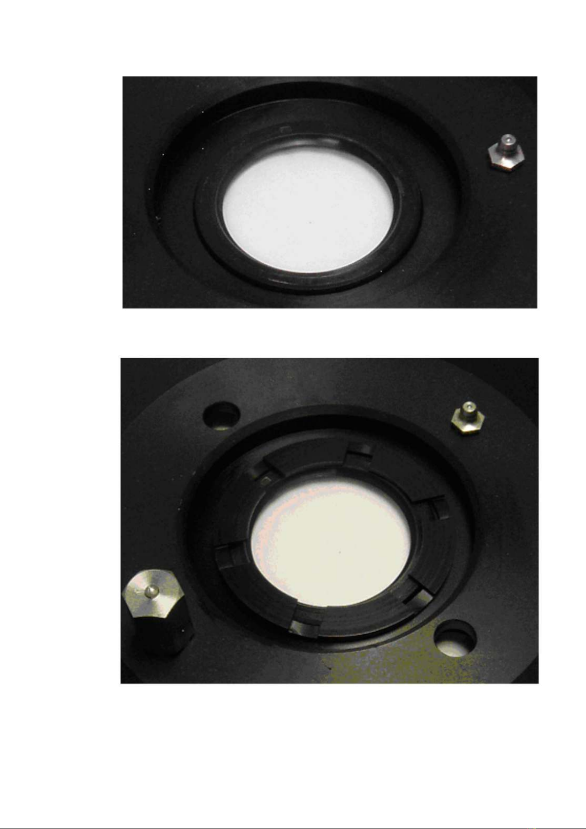
Maintenance SuperZip
0711-SOM-00003, Issue: 05 19 © Tritech International Ltd.
Figure 5.1. Impeller Seal
Figure 5.2. Seal Retaining Clip

Maintenance SuperZip
0711-SOM-00003, Issue: 05 20 © Tritech International Ltd.
Place the ID100x2mm o-ring onto the motor and apply some silicon grease
around the surface. Mount the motor on the motor mount disk and secure
(see Figure 5.3, “Motor Mount Disk”).
Figure 5.3. Motor Mount Disk
Apply some anti-seize grease to the motor shaft before fitting the impeller.
Press the impeller boss onto the shaft right up to the shoulder.
Place the ID20x3.5mm o-ring over the top of the motor shaft, assemble the
retainer onto the shaft end and secure the setscrew using a small quantity
of Loctite.
Replace the impeller on the boss and secure the four countersunk screws
with Loctite.
Slowly fill the motor face cavity with grease until the compensator piston
shows the fill mark and grease flows out of the relief port (see Figure 5.4,
“Compensator Piston”).
Table of contents
Other Tritech Water Pump manuals


