Triumph Tigress TW2 User manual


SCOOTER
Printed December 1959.
250 c.c. O.H.V. TWIN CYLINDER SCOOTER
REMOVING THE SIDE VALANCES
To remove the s de valances for ma ntenance on the eng ne un t, take off
the dual seat by remov ng the two 1/4 n. nuts and bolts coupl ng the "C"
shaped h nges to the dual seat brackets.
Take out the three 3/16 n. bolts, two at the front of the valances and one
at the rear bottom end. Then remove the two 1/4 n. d ameter nuts and bolts
wh ch secure the number plate.
When a spare wheel and rear carr er are f tted the number plate s on the rear
carr er and need not be removed from the carr er.
Break the connectors to the rear lamp. These w ll normally be found
underneath the rubber tool tray, but when a rear carr er and spare wheel are
f tted the connectors w ll be well outs de the valances and w ll be obv ous.
When a spare wheel s f tted, undo the two wheel nuts, slacken off the
two bolts at each s de of the dual seat that support the rear carr er, l ft the
carr er and take off the spare wheel. Then take out the two bolts at the s des of
the dual seat and remove the carr er complete w th number plate. Remove the
two 5/16 n, bolts at the m ddle rear of the valances, wh ch also hold the spare wheel
brackets.
The valances w ll now only be held by two bolts at each s de, one domed
slotted bolt mmed ately below the dual seat and one round head bolt at the
bottom edge mmed ately above the p ll on passenger's footboards. On the r ght-
hand s de of the mach ne the dual seat catch knob must also be removed. The
valances are now ready to be taken away complete w th the plast c
head ngs.
Reassembly of the valances s the complete reverse of d smantl ng.
They should therefore be located f rst by ref tt ng the two domed head slotted bolts
mmed ately below the dual seat and the round head bolts above the p ll on
passenger's footboards, but these two bolts should be left slack to
fac l tate ref tt ng the bolts around the edges of the valances.
It s a w se precaut on to locate all the bolts through the bead ng
before t ghten ng.(best to locate these n the bead ng as taken out;
regreased w th copper grease IMO)

250 c.c. O.H.V. TWIN CYLINDER SCOOTER
DISMANTLING FOR DECARBONISING
The term decarbon s ng means the removal of all carbon depos ts from the combust on
chambers,p ston crowns and ports. It s generally recogn sed as nclud ng attent on to valves, gu des
and spr ngs. You w ll need these tools below.Most of wh ch are easy to f nd or mod fy, except for
nlet valves and the steel gasket nowdays.
1. Top overhaul gasket set number 00-3120. 7. Valve gr nd ng tool (suct on type). 61-5035
2. Inlet valves number 76-60(2). 8. Valve gr nd ng paste.
3. Exhaust valves number 76-61(2). 9. Scrapers for remov ng carbon.
4. Valve spr ngs number 76-63(4) & 76-69(4). 10. Set of feeler gauges.
5. Valve gu des number 76-15(4). 11. Supply of clean eng ne o l.
6. Valve spr ng compressor number 61-5001.
In order to carry out the work of decarbon s ng some d smantl ng s necessary and these nstruct ons are
for the gu dance of owners w sh ng to undertake th s job themselves. Care should be taken to avo d damage
to nuts, bolts and other f x ngs by the use of ncorrect tools, and as parts are removed the f x ng bolts should
be replaced and the nuts just started so that they are not lost and to fac l tate reassembly.
(a d g tal camera can be used to take p cs as you go,th s can be helpful when try ng to relocate the
correct or entat on of p eces,espec ally f the project stays apart for ages)
Before the eng ne can be d smantled t s necessary f rst to remove the dual seat and s de valances. The
seat s held by two bolts and nuts secur ng " C" shaped brackets, and the s de valances are secured by eleven
bolts, all of wh ch must be removed together w th the dual seat catch knob:
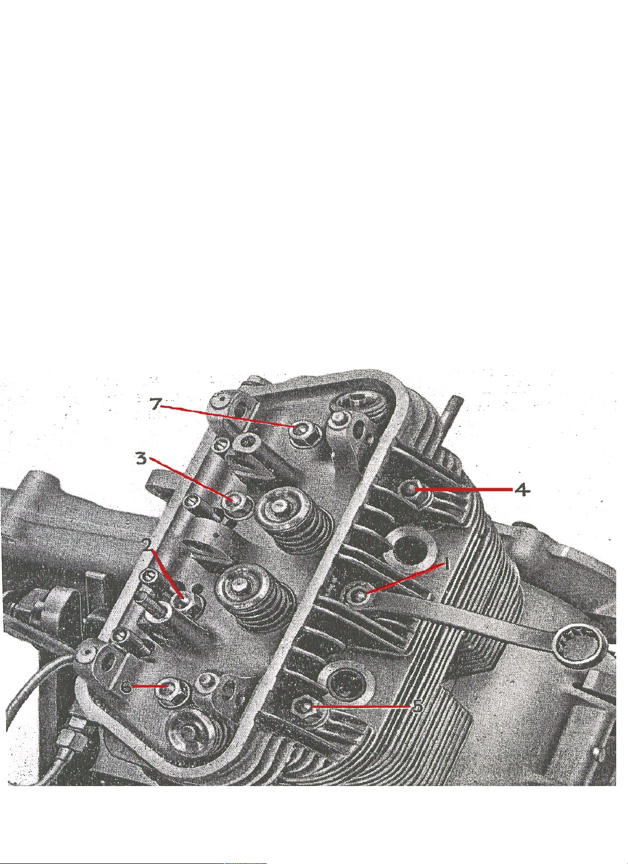
Detach the spark ng plug leads and remove the cyl nder head cowl and rocker cover. The cowl s held by
two nuts, one at each end of the cyl nder head, and the cover by two nuts on top. Note that removal of the
cowl does not release the exhaust p pe flanges and that t s necessary to take off two further nuts secur ng
these flanges before the exhaust p pes can be moved away from the cyl nder head.
There s no need to d sturb the connect on between the carburetter and ts man fold. All that s
necessary s to take off the two nuts secur ng the man fold to the cyl nder head and the carburetter can then be
moved suff c ently to one s de to allow d smantl ng to proceed.
Slacken off the lower un on of the rocker o l feed p pe and unscrew the upper un on completely to allow
the p pe to sw ng out of the way.
Remove the spark ng plugs and take off the seven cyl nder head nuts. These nuts w ll requ re a small
cranked r ng spanner to remove.
The cyl nder head can now be taken from the block for decarbon s ng. Th s w ll reveal the cyl nder head
jo nt face gasket wh ch should be removed and exam ned. Replacement s generally des rable.
Removal of carbon s best done us ng a s mple scraper, but t s mportant to avo d damage to the soft
alum n um cyl nder head and p ston crowns. Any marks on the jo nt faces w ll g ve r se to gas leakage and
may lead to further damage by burn ng after the eng ne s reassembled. To fac l tate attent on to the p stons
they should be turned to top dead centre ( .e. as far as they w ll come) and th s pos t on can be ach eved by
engag ng top gear and rotat ng the rear wheel.
nb:(try not to use a sharp metal scraper, a good plast c scraper w ll do now days,also st ll be careful not to
scratch the surface as the alum n um s soft)
Hav ng removed all traces of carbon, carefully clean all parts w th a sl ghtly o led rag, be ng sure to move
the p stons down the cyl nders to enable carbon to be w ped from the top of the cyl nder bores where t w ll
have gathered above the top p ston r ngs.
The opportun ty should now be taken to exam ne the valves, and for th s to be done they must be
removed us ng Serv ce Tool number 61-5001. The rockers need not be d smantled.
Be very careful not to lose the spl t collets, wh ch w ll be released when the valve spr ng has been com-
pressed. It s a w se precaut on to remove all the valves before cont nu ng w th any other work and to put
them together w th the r respect ve collets and caps carefully on a shelf or n a box,(or plast c z p bags can be
wr tten on w th cd marker pen) nd cat ng from wh ch pos t ons n the cyl nder head they were removed.
Service Sheet No. 100 (contd.)
Scrape all carbon from the ns de of the ports, ( .e., the passages n the cyl nder head wh ch allow the
entry and ex t of gases.) Take care to avo d damage to the seats. (These are the angular faces n the
cyl nder head, wh ch, when mated w th s m lar seats on the valves, prov de a gas-t ght seal.) Clean up the
valves by careful use of f ne emery cloth.
Unless the eng ne has covered a cons derable m leage, t s unl kely that anyth ng but a s mple gr nd ng n
operat on w ll be necessary to restore the valve seats to perfect cond t on. Valve gr nd ng s done by smear ng
a small quant ty of gr nd ng paste (obta nable from any Dealer) on the valve faces, re- nsert ng them nto the r
gu des and rotat ng backwards and forwards. The valve should be moved round to a new pos t on after every
few movements. Th s should not be overdone, or n t me valve pocket ng, w th
consequent lack of eff c ency, w ll develop.
If cons derable p tt ng of the seats s ev dent they must be recut and the valves e ther reground or
replaced. Th s s best left to a Dealer, who w ll have the necessary serv ce tools. Th s you do have to be
careful w th.
Before reassembl ng, clean off all traces of paste and smear the parts w th clean eng ne o l.
Reassembl ng s undertaken n the reverse order, but note should be taken that t s a w se precaut on to
replace valve spr ngs when decarbon s ng. They are not expens ve and replacement w ll help to ma nta n
the eff c ency and performance of the eng ne.
The part numbers of the valve spr ngs are 76-69, 76-63, nner and outer respect vely. When ref tt ng
valves part cular care should be taken to ensure that the collets are correctly seated.
The cyl nder head hold ng down nuts should always be t ghtened n the order shown n F g. 1, and each nut
must be pulled down a l ttle at a t me to avo d d stort ng the head.
F g. 1.
Cyl nder Head Nut T ghten ng.

SCOOTER SERVICE SHEET
50 c.c. O.H.V. TWIN CYLINDER SCOOTER
REMOVAL OF THE ENGINE, GEARBOX AND FINAL DRIVE NUT
When the eng ne and transm ss on are removed for overhaul they must be taken out as a complete un t
compr s ng the eng ne, gearbox and f nal dr ve.
Remove the s de valances as descr bed n Serv ce Sheet No. 1001.
1003
Printed December 1959.
Dra n off all the o l by remov ng the lowest Ph ll ps head screw and the f ller plug on the pr mary and the
rear dr ve hous ngs, the two 1/4 n. bolts at the rear of the gearbox, and the dra n plug n the base of the
sump.(th s can be the b t where your whole b ke can end up covered n o l,so use plenty of paper/t ssue on the
floor rubbers around the dra nage area,the concrete or surface underneath the b ke)
Ra se the rear wheel clear of the ground. For th s purpose a block or small wooden trestle as F g. 2 s
necessary and ass stance w ll be requ red to l ft the mach ne and place the block underneath the rear cross
channel on the frame.(The Chu recommends a decent s zed block so she wont fall off)
Remove the rear wheel by tak ng off the three hub nuts, wh ch have a normal
r ght-hand thread. These nuts are countersunk both s des and can be f tted e ther way.
Now take off the a r duct ng around the cyl nder head; t s secured by two small
nuts on 1/4 n. d ameter studs wh ch also secure the exhaust p pes.
After these nuts are removed take out the one 1/4 n. d ameter bolt wh ch
secures the carburetter a r p pe; th s s on the top cross member between the two
vert cal p llars of the frame, and s mmed ately below the petrol tank.
D sconnect the spark ng plug leads.
Now pr se off the lug secur ng the a r duct on the left-hand stud and l ft the a r
duct ng complete w th the carburetter a r p pe clear and place on one s de.
Next remove the exhaust p pes by tak ng off the rema n ng 1/4 n. nuts from the
studs nearest the rear wheel, and slacken off the cl ps secur ng the exhaust p pes to
the s lencer and the two bolts at the top of the s lencer. Th s w ll enable the
s lencer to be swung away from the p pes and the exhaust p pes can then be taken
off the studs secur ng them to the cyl nder.
The r ght-hand s de exhaust p pe also carr es the spr ng, wh ch tens ons the
k ckstarter cha n. The spr ng w ll therefore have to be unhooked from the exhaust
p pe and the cha n l nk before the r ght-hand p pe can be placed on one s de.
F g. 2.
F g. 3
D sconnect the speedometer dr ve from the rear hub by
unscrew ng the un on nut (F g.3). The speedometer dr ve
cable s the upper of the two cables wh ch run to the rear
wheel, the lower one be ng the brake cable. Also d sconnect
the rear brake cable by tak ng out the spl t p n and clev s
p n wh ch secure the cable end to the brake lever on the rear
hub.
Remove the two black and yellow w res wh ch run from
the d str butor to the left-hand and r ght-hand gn t on co ls by
tak ng off the two nuts on top of the co ls. Note that the
longer of the two cables (black and yellow) goes to the r ght-
hand co l.
W th a su table tool such as a screwdr ver or a hammer
shaft, press n the clutch lever on the eng ne, sl p the n pple
out of the lever, pull the outer cas ng out of the lug and
place the spr ng on one s de. Push the cable down under the
frame out of the way.

Service Sheet No. 1003 (contd.)
Make sure that the petrol tap s turned off and uncouple the banjo un on at the carburetter end of the
petrol p pe. Be careful not to lose the two f bre washers or the small gauze f lter wh ch s f tted ns de the banjo
un on.
The petrol tap rod s supported by a bracket wh ch s secured to the nears de rocker cover stud; remove the 4
¼ nch nut on ts stud l ft the bracket off the stud and sw ng t to one s de. Replace the nut loosely on the
stud to reta n the f bre and steel washers.
On the r ght-hand s de of the mach ne w ll be seen the gearchange lever, f tted to the quadrant sp ndle; take
off the nut secur ng the lever to the sp ndle end and pr se the lever off the squared end of the sp ndle.
Now depress the k ckstarter lever and d sconnect the cha n from the lever by remov ng the spr ng
l nk.
The k ckstarter sprocket and the cha n can be removed after the un t has been taken out of the frame,
but the sprocket can be removed at th s stage f necessary, t s f tted on to a taper shaft wh ch s keyed.
Remove the nut secur ng the sprocket, and w th an open-ended spanner beh nd the sprocket and aga nst
the adjacent Ph ll ps head screw, tap the end of the spanner sharply so as to jerk the sprocket from the
taper on the shaft.
D sconnect the speedometer dr ve from the rear hub by unscrew ng the un on nut (F g. 3). The
speedometer dr ve cable s the upper of the two cables wh ch run to the rear wheel, the lower one
be ng the brake cable. Also d sconnect the rear brake cable by tak ng out the spl t p n and clev s
p n wh ch secure the cable end to the brake lever on the rear hub.
Remove the two black and yellow w res wh ch run from the d str butor to the left-hand and r ght-
hand gn t on co ls by tak ng off the two nuts on top of the co ls. Note that the longer of the two
cables (black and yellow) goes to the r ght-hand co l.
W th a su table tool such as a screwdr ver or a hammer shaft, press n the clutch lever on the
eng ne, sl p the n pple out of the lever, pull the outer cas ng out of the lug and place the spr ng on
one s de. Push the cable down under the frame out of the way.
It w ll now be necessary to turn to the left hand s de of the mach ne, and here w ll be seen the curved support
arm on the rear dr ve un t. Th s support arm must be removed before the un t can be taken out of the frame,
s nce t passes round the left-hand vert cal column of the frame.
Unscrew the three nuts at the rear of the curved arm wh ch secure t to the rear dr ve and remove the hollow
bolt at the front end of the curved support arm, (th s s the bolt wh ch also carr es a grease n pple). Take off
the large d ameter steel washer wh ch s pegged.
Now d sconnect the lower end of the rear suspens on damper un t, and sw ng the damper un t up and out of the way.
Ra se the rear dr ve and gently pr se off the curved support arm. L ft ng the rear dr ve un t w ll allow
suff c ent clearance for the support arm to pass over the p ll on passenger's footboard.
The three bolts wh ch secure the rear end of the support arm should now be taken away s nce they are
l able to foul the frame as the un t s be ng removed.
Remove the rear mudguard by tak ng out the four 1/4 n. d ameter nuts and bolts, two at the front on
the cross member between the two vert cal tubes of the frame and two at the rear wh ch also carry the
s lencer and petrol tank support bracket.
Unscrew the two 3/8 n. nuts on the bolts attach ng the eng ne un t to the two vert cal frame tubes at
the rear of the frame. On the left-hand tube t w ll also be necessary to take out the two 1/ 4 n. bolts secur ng
the quarter port on of the cl p. Dr ve the bolts part ally through but st ll allow them to support the eng ne.
Now remove the front eng ne plates by tak ng off the nuts on the two crankcase studs and remove the two
5/16 n. bolts and nuts wh ch secure the "L" shaped eng ne plates to the chass s cross member. When the
bolts secur ng the plates to the cross member have been removed sl de the plates off to left and r ght from
the studs. The eng ne w ll now be supported only by the two 3/8 n. bolts through the rear brackets.
D sconnect the generator cables by break ng the connectors wh ch w ll be found underneath the
floorboards. Th s operat on w ll be eas er to carry out f each connector s broken nd v dually.
The un t s now ready to be taken out of the frame, and t s qu te easy to do so prov d ng the correct
procedure s adopted, wh ch s to dr ve out the two bolts hold ng the eng ne to the vert cal frame tubes, t lt
the un t forward so that the lugs on the eng ne clear the lugs on the frame and then t lt t s deways
towards the left-hand s de, at the same t me l ft ng t out. Th s w ll enable the rear dr ve to pass between
the two vert cal tubes.(Caut on to do ng yourself an njury through th s as t s awkward and heavy)
Complete d smantl ng of the eng ne, gearbox and f nal dr ve un t s descr bed on Serv ce Sheet No. 1004.

50 c.c. O.H.V. TWIN CYLINDER SCOOTER
COMPLETE DISMANTLING OF THE ENGINE, GEARBOX AND
FINAL DRIVE NUT
If the o l has not already been dra ned from the un t t should be done at th s stage. To dra n
the f nal dr ve take out the Ph ll ps head screw mmed ately below the o l level plug and remove
the o l level plug as well. The pr mary dr ve s on the left-hand s de of the un t and carr es the
clutch lever and the contact breaker un t; to dra n, remove the Ph ll ps screw mmed ately below
the rear or f nal dr ve bear ng and aga n remove the o l level and f ller plug to allow the o l to
flow.
To dra n the gearbox, remove the two hexagon bolts, one above the other, at the rear of the
gearbox just beh nd the gearchange assembly. The sump s dra ned by remov ng the plug on the
r ght-hand s de bottom corner of the sump; th s s the rectangular conta ner under the eng ne. ,
D smantl ng should only be undertaken by someone w th mechan cal exper ence, otherw se
ser ous harm could result to the un t. If n doubt place the job n the hands of the Dealer.
Before clean ng off any accumulat on of o l or dust look for obv ous s gns of o l leakage. The
po nts where th s occurs usually show as very clean spots whereas the rest of the un t, though
o ly, w ll also be d rty w th an accumulat on of road dust.
Where the un t s heav ly coated w th dust and o l t s as well to wash t comparat vely clean
before d smantl ng.
Dur ng the actual d smantl ng care should be taken to look for s gns wh ch show that a
part cular part requ res replacement. In the case of bear ngs they should be clean and pol shed, f
there are any score marks or s gns show ng that the metal has "p cked up" the bear ng or bush
should be replaced. Ball or roller bear ngs should sp n qu te freely w thout excess ve play, and f
there are s gns of lump ness or gr t n them, t s an nd cat on that the balls or rollers or the races
are p tted and here aga n the parts should be replaced.
It s good pol cy to use only sound and unworn spanners and n certa n cases, t s essent al that
an appropr ate serv ce tool s handy. Deta led below are those serv ce tools wh ch are used for
d smantl ng the un t. Although one or two operat ons can be done w thout them, such as removal
of the valve spr ngs and contact breaker, (these are covered by serv ce tool number 61-5001 and
5005 respect vely), the use of the tools w ll fac l tate the work.
Serv ce tools are as follows:
61-5001 Valve spr ng compressor.
61-5002 Extractor for generator and flywheel.
61-5005 Extractor for contact breaker cam and auto advance un t.
61-5007 Extractor for clutch.
61-5019 Extractor for speedometer dr ve. 61-
5022 Crankshaft holder.
61-5025 Un versal extractor (for pr mary dr ve and t m ng p n on-)
Service Sheet No. 1004 (contd.)
Dismantling Drive Side of Unit
W th the spanner prov ded n the toolk t remove the two spark ng plugs, take off the two ~ n. nuts hold ng
the rocker box cover, remove the steel washers and f bre washers and remove the cover. Exam ne the cover
gasket to dec de whether or not t can st ll be used. If the gasket s damaged n any way, as for example, f
parts of t have adhered to the cyl nder head, or f t s compressed too th n, t s adv sable to use a new one.
Slacken off the two un on screws hold ng the o l feed p pe to the rocker box and crankcase, and remove the
p pe, leav ng the un ons screwed nto both the crankcase and cyl nder head.
Remove the seven nuts and washers wh ch hold the cyl nder head to the block. Four of these are at the rear
ns de the rocker box and three at the front adjacent to the spark ng plugs. The smaller r ng spanner prov ded n
the toolk t s the most su table tool to use on these nuts. Take off the cyl nder head and n th s case, although the
gasket may appear to be n good cond t on, s nce t, s, a, comparat vely cheap and certa nly an mportant tem, t
s adv sable to use a new one when reassembl ng.
There may be no need to d smantle the rocker assembly but n case th s operat on s descr bed at a later
stage.
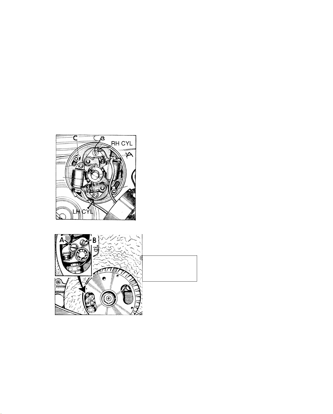
A standard type of screwdr ver can be used to take off the contact breaker cover by remov ng the two 3/16 n.
screws, follow ng wh ch the cover can be placed to one s de after the rubber grommet hold ng the leads has been sl d
out of the "U" shaped slot n the cover. Unscrew the two long hexagon nuts (C) F g. 4, wh ch are sl ghtly to the
left and r ght of the contact breaker plate and take off the plate complete w th the leads after d sconnect ng the
black and wh te lead from the left-hand gn t on co l and the black and yellow lead from the r ght-hand co l.
The contact breaker cam and automat c advance and retard un t s reta ned by the centre bolt wh ch s now
175 Contact breaker
letters shown are not
for this page

Service Sheet No. 1004 (contd.)
When all the screws, nuts and bolts are removed, the pr mary dr ve cover can be taken off,
the jo nt be ng broken by gently tapp ng the cover w th a rawh de mallet or a hammer shaft but
great care must be taken or the cover may be cracked or d storted.
The clutch push rod w ll come away w th the cover. The cond t on of the phosphor bronze
pad on the push rod should be carefully noted and f t shows s gns of hav ng worn or the metal
hav ng "p cked up", the push rod should be replaced. Make sure that the small rubber "0" r ng
on the push rod shaft s n good cond t on, and f necessary replace t to prevent leakage of o l
through the push rod bore. The f nal dr ve, support arm bear ng s a press f t nto the pr mary
dr ve cover and f t s to be removed the cover should be heated n bo l ng water, and the
bear ng dr ven out w th a su table punch through the hole n the hous ng. The replacement must
be f tted wh le the cover s st ll hot. (Th s method should be employed whenever a bear ng s to be
removed from an alum n um case.) The contact breaker dr ve s s mply a sl d ng f t n the
bronze bush n the rear pr mary dr ve case.
Before remov ng the clutch, flatten
the tab washer on the larger pr mary
dr ven gear and slacken off the centre
nut. Th s operat on w ll be fac l tated
f the un t s placed n gear by
operat ng the gearchange sp ndle and
the brake ' appl ed w th a su table
length of tube over the brake lever.
Now unscrew the three clutch
pressure spr ng nuts. To avo d
t lt ng the plate and lock ng the
nuts g ve each nut approx mately
one full turn at a t me. When all
the nuts are off take off the spr ngs
and place the pressure plate on one
s de. Then replace the spr ng and
nut on one of the studs to keep the
un t ntact dur ng d smantl ng. Remov ng Clutch Un t
Flatten the star shaped tab washer
under the clutch centre nut and F g. 5.
remove the nut, aga n lock ng the un t n the manner just descr bed. Great care must be taken to
avo d damag ng the clutch spr ng studs for they can very eas ly be bent f the spanner sl ps.
When the nut s off remove the star washer and, us ng serv ce tool number 61-5007, draw off
the clutch centre and clutch complete as n F g. 5.
The clutch hous ng and gear s a push f t over the bear ng and can be taken off w thout an
extractor. It should be noted that there s a thrust washer between the end of the clutch sleeve
and the spl ned clutch centre, and th s washer has the chamfered face outwards towards the
clutch.
The dr v ng and dr ven plates should be carefully exam ned. If the steel dr v ng plates are
badly scored they should be replaced and f the bonded dr ven plates have the segments worn
th n these also should be replaced. (The sequence of assembly s f rst a dr ven plate w th a bonded
l n ng aga nst the rear pressure plate, than a pla n steel dr v ng plate and so on alternately.
`
The pla n steel clutch hous ng bear ng sleeve can be sl d off the ma nshaft. Note that t s f tted w th the larger d ameter towards the
eng ne.
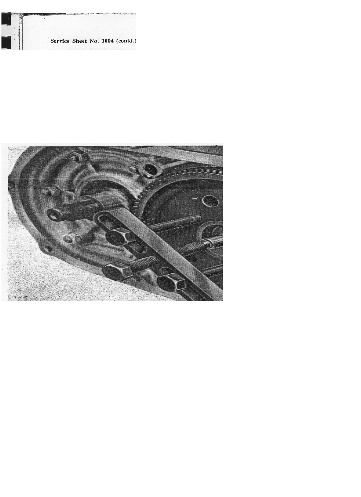
Hav ng prev ously flattened the tab washer and slackened off the nut on the large pr mary dr ven gear, th s gear can now be drawn off the
gearbox ma nshaft us ng serv ce tool number 61-5025 f tted w th the short extractor legs 61-1732 (F g. 6). The f nal removal of the gear
should be carr ed out w th care, and f poss ble w th the key n the gearbox ma nshaft at 12 o'clock pos t on s nce f the key s loose
and drops down beh nd the o l seal t may cause damage.
Unscrew the s x 4 n. nuts hold ng the pr mary dr ve nner cover to the crankcase and remove the washers. The jo nt can be broken by
tapp ng gently w th a rawh de mallet or someth ng s m lar. The nner cover also carr es the crankshaft ma n bear ng hous ng and f th s bear ng s
to be changed ow ng to not ceable roughness or up-and-down play t w ll be necessary to flatten the tab washers on the four reta n ng bolts,
remove the bolts and take off the bear ng plate.
The bear ng tself can then be
removed from the nner dr ve cover
by heat ng the case n bo l ng water
and then tapp ng gently out on to a
wooden bench. The replacement
should be f tted wh le the cover s
st ll hot and the replacement
bear ng s cold. There s also an
o l seal n the cover, wh ch s
f tted from the ns de, ( .e., the
clutch s de w th the l p towards the
bear ng.)
Beh nd the pr mary dr ve nner
cover there s a rubber "O" r ng
pressed on to the boss on the
outs de of the outer cha n cover.
If th s "0" r ng has become soft
or enlarged then a replacement
should be f tted on reassembly.
Remov ng Pr mary Gear
F g. 6. It w ll now be poss ble to remove the outer cha n cover by tak ng
out the n ne Ph ll ps head screws, but careful note should be made of the r respect ve pos t ons and
lengths. Before f nal removal of the cover take out the cha n adjuster screw by unscrew ng the
locknut and remov ng the screw completely.
Aga n break the jo nt by tapp ng gently w th a rawh de mallet and remove the cover. Th s
may come away complete w th the sl pper pad and ts fulcrum p n, or the pad may rema n n
the rear port on of the sw ng ng arm case. It should be noted that the pad must be qu te free on
the bear ng p n.
In the outer cha n cover w ll be found a ball bear ng at the rear and an o l seal at the front.
The ball bear ng can be removed by heat ng the case n bo l ng water and then tapp ng gently on
to a bench. The o l seal s f tted from the outs de of the case, w th the l p po nt ng nwards. When
replac ng care should be taken to ensure that t s f tted squarely n the hole and s not t lted to
one s de. The Woodruff key n the gearbox ma nshaft should now be removed carefully to avo d
damage to the key or to the shaft.
Service Sheet No. 1004 (contd.)
Flatten the tab washer on the rear cush dr ve un t and unscrew the nut, lock ng the
assembly by apply ng the rear brake. The nut has a normal r ght-hand thread. The gearbox
sprocket nut has no tab washer and s also unscrewed n a normal ant -clockw se d rect on.
Here aga n t w ll be necessary to lock the un t by apply ng the rear brake, or alternat vely by
apply ng a substant al tool between the rear hub studs and lock ng aga nst the bench.
Now remove the s ngle countersunk screw wh ch reta ns the brake drum on the Stub axle
and sl de the drum off. Us ng a rawh de mallet or copper hammer, gently tap the stub axle
through the cush dr ve towards the wheel s de. The cush dr ve can then be taken out of the
cha n and the gearbox sprocket together w th cha n can be taken off the spl ned gearbox ma n-
shaft.
Beh nd the cush dr ve and rear sprocket assembly are the speedometer dr ve and thrust
washer, the latter be ng between the speedometer dr ve and the rear sprocket, and ns de the nner
cha n cover s a bear ng reta ned by a lock r ng hav ng a normal r ght-hand thread. To remove
th s bear ng t w ll be necessary f rst to extract the speedometer dr ve us ng serv ce tool number 61-
5019. When th s s taken out t w ll be seen that there s a pressure pad let nto the case at the
oppos te end of the speedometer
dr ve. .
After the bear ng lock r ng has been removed, the
case should be heated n bo l ng water and the bear ng
dropped • out n the manner prev ously descr bed, and
the replacement, f necessary, f tted wh le the case s
st ll hot, Note that the speedometer dr ve s f tted w th
the flange outwards, ( .e., towards the cush dr ve and
rear sprocket un t). The pla n steel washer can be
f tted e ther way round.
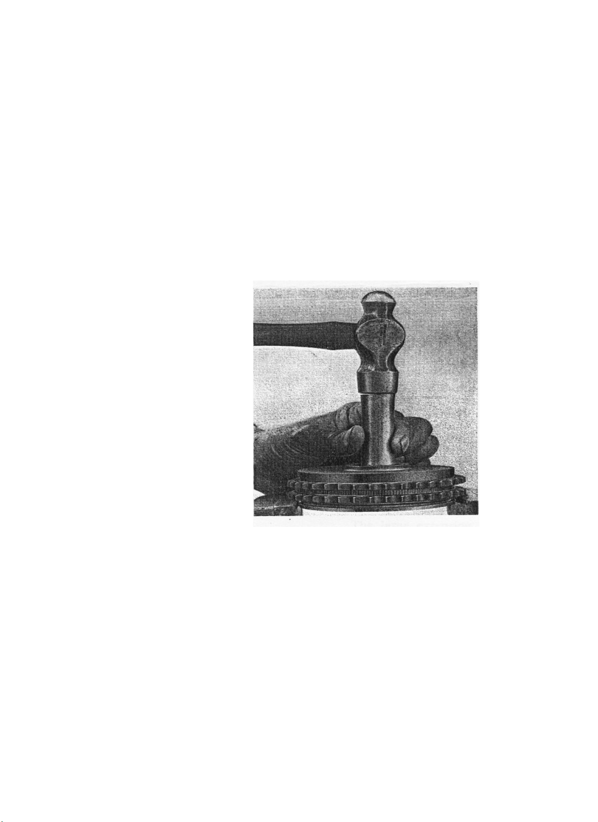
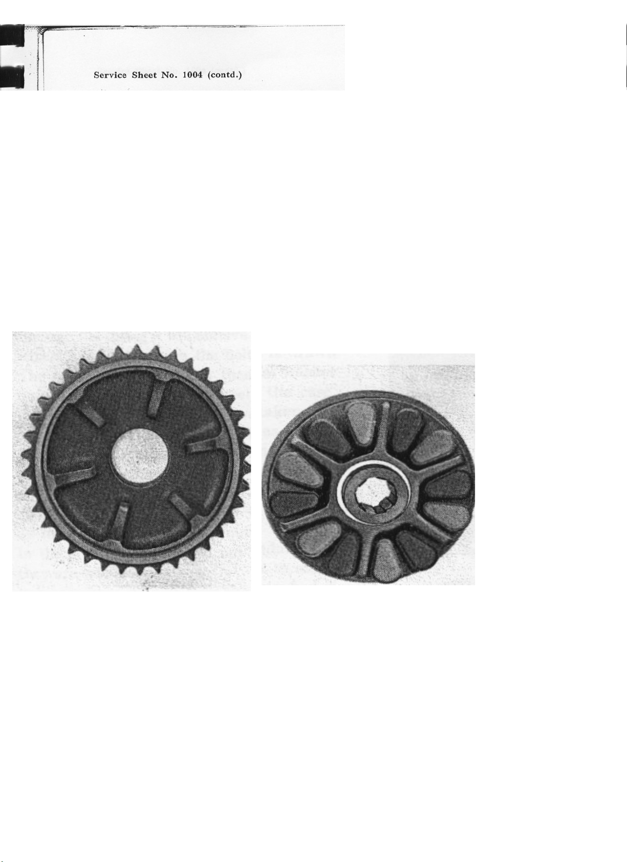
If the cush dr ve s to be d smantled for f tt ng
new rubbers the sp der should be pressed out of the
sprocket us ng a wooden plug or s m lar tool on the
centre spl ned port on and support ng the sprocket on
one of the double row of teeth, as n F g. 7. Do not
attempt to pr se the sp der out w th a screwdr ver
under the flange as th s may cause the flange to break
away.
The cush dr ve compr ses twelve rubbers, wh ch
are f tted between the sp der and sprocket vanes. On
some early models all twelve rubbers were soft ; later
models employ s x soft and s x hard rubbers,
the hard ones be ng f tted mmed ately to the left of the vanes look ng ns de the rear sprocket, as
n F g. 8. These hard rubbers are usually pa nted wh te.
Take off the rear brake shoes by press ng the lower shoe down and at the same t me tw st ng
t off the brake cam and fulcrum p n. The nner cha n cover can now be taken off the p vot stub.
Note the rubber "0" r ng on the stub.
The phosphor bronze bush n the front end of the cover s a press f t and the usual method
of
extract on should be employed f t s worn and therefore to be replaced.
Part ng the Cush dr ve
F g. 7.
An o l seal s f tted n the cover from the brake shoe s de, aga n w th the l p of the o l seal
fac ng nwards towards the bear ng. If a replacement s to be f tted the old seal can be pr zed
out w th a screwdr ver but care should always be taken when f tt ng a new o l seal to see that t
s nserted squarely nto the hole, and great care should be taken to avo d any damage to the
feather edge of the seal.
The brake cam sp ndle can be removed by tak ng off the nut beh nd the brake arm, and
draw ng the cam out towards the hub s de. If, however, the cam s qu te free n the hous ng and
there s no apparent excess ve wear on the cam face there s no need to d sturb t. The fulcrum
p n s secured by a nut on the ns de of the cover; here aga n there s no need to d sturb t unless
there s obv ous damage. The two locat on dowels n the cover should be undamaged and a good
f t n the r holes.
Dismantling Timing Side of Unit
D smantl ng of the left-hand or pr mary dr ve s de s now completed and attent on can be
g ven to the r ght-hand s de of the un t.
If the fan cowl has not already been removed, unscrew the three small Ph ll ps head screws
If the fan cowl has yet to be removed, unscrew the three small Ph ll ps head screws and the one
pla n screw at the top r ght-hand front wh ch also carr ed the throttle cable cl p. Unscrew and
remove the nut secur ng the k ckstarter sprocket and remove the sprocket complete w th the cha n
and spr ng. Take out the Woodruff key, be ng careful not to damage the key or the slot n the shaft.
The large extens on nut secur ng the flywheel and fan can now be re moved by screw ng n a
normal ant -clockw se d rect on, us ng an 11/16 n. Wh tworth r ng spanner. The crankshaft,
however, must be prevented from turn ng by hold ng the oppos te s de w th serv ce tool number
61-5022.
W th the flywheel centre nut removed, the flywheel can be extracted w th serv ce tool number
61-5002. Th s w ll expose the stator un t secured to the crankcase by three 5/16 n. nuts and
washers, wh ch should be unscrewed us ng a tubular spanner to avo d damage to the
Cush Dr ve Rubber Assembly F g. 8.

Service Sheet No. 1004 (contd.)
stator un t. W th the nuts and washers removed the stator can be drawn off the three studs by
s mply pull ng t away and thread ng the leads through the rubber grommet n the back of the
case. The three d stance p eces on the studs should be taken away to avo d be ng lost n
subsequent d smantl ng. Carefully pr se out the Woodruff key from the ma nshaft, aga n tak ng
care to avo d damage to the key or the slot n the shaft.
If the mach ne s f tted w th a starter motor, the two 5/16 n. bolts secur ng the motor to
the back of the t m ng gear cover should be removed and the starter taken away. In the case of
models w thout starter a blank ng plate s f tted n l eu of starter and th s plate need not be
d sturbed.
Sl ghtly to the left of the starter sprocket s a project on hav ng two flats; th s s the cam
plate plunger hous ng. Us ng a spanner wh ch s a good f t on the two flats, unscrew the hous ng n a
normal ant -clockw se d rect on and remove t complete w th the plunger and spr ng.
The gearbox end cover can now be removed after the f ve Ph ll ps head screws have been
taken out ; aga n the jo nt w ll have to be broken by tapp ng gently w th a rawh de mallet.
Removal of the end cover .w ll expose -the outer port on of the cam plate and the selector
quadrant together w th ts sc ssor spr ng, -the
spr ng be ng reta ned n the nner cover by 'a large hexagon-headed bolt. Unscrew th s large bolt and draw
t out not ng that as t s drawn through the spr ng t w ll remove the star washer wh ch s f tted between the bolt
and the case. The selector quadrant can then be taken out qu te eas ly f a th n str p of steel such as a table
kn fe s sl pped between the two plungers and the cam plate. (See F g. 9). The other end of the quadrant
sp ndle s s mply a push f t nto the back of the case.
The two plungers should be undamaged on the r chamfered ends and qu te free to move n the hous ng,
and should not be d sturbed f they are sat sfactory.
The next operat on s to remove the t m ng and gearbox cover wh ch s n one p ece.
Take out the f ve large countersunk screws
hold ng the t m ng cover around the crankshaft and the f ve Ph ll ps head screws on the gearbox cover port on.
(Two of these are ns de the gearbox port on on the left-hand s de of the selector quadrant.) Do not d sturb the slotted
screw on the t m ng cover port on ; th s reta ns the k ckstarter stop plate. See F g. 10.
W th all screws removed the cover can now be w thdrawn, br ng ng w th t the gearbox
ma nshaft, cam plate, selector forks, layshaft and gear cluster. See F g. 11.
Remov ng Selector Quadrant
F g. 9.
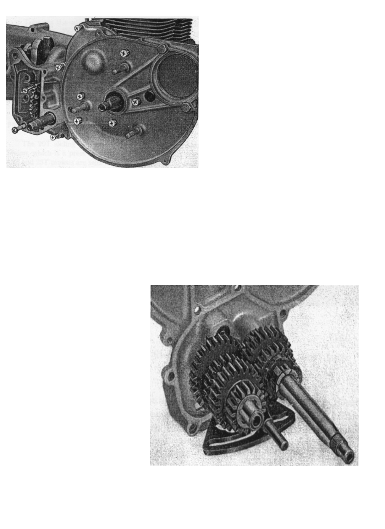
As the assembly s drawn
out t may be that the thrust
washer wh ch s f tted to the
ma nshaft w ll drop nto the
case. Look for th s washer and f
t does drop replace t tem-
porar ly on the gearbox ma n-
shaft so that ts locat on s
remembered. It w ll be necessary
dur ng th s operat on to hold the
cam plate centrally to avo d
foul ng e ther the upper or lower
port ons of the gearbox case.
In some cases the selector
fork sp ndle may rema n n the
gearbox. It s s mply a push f t
nto the gearbox and the cover.
Gearbox and T m ng Cover Screws.
F g. 10.
At, th s stage t should be noted that there s a poss b l ty of the top front eng ne mount ng
stud dropp ng out of the crankcase f t s an easy f t n the case, and s nce t s essent al that
th s stud s n pos t on before the gearbox and t m ng cover and the pr mary dr ve nner covers are
f tted the po nt should be borne n m nd for reassembly. It s therefore, a w se precaut on to replace
the two nuts on to th s stud so that t s reta ned n pos t on.
The only parts now left n the gearbox are the p n on sleeve and the ma n bear ng. The
p n on sleeve can be dr ven through the bear ng nto the gearbox and th s w ll release the gearbox
sprocket d stance p ece wh ch f ts over the p n on sleeve on the outs de of the gearbox.
The p vot stub for the cha ncase sw ng ng arm un t s f xed to the bolts
and two lock ng plates that are turned up over the bolts. It that the stub
w ll have to be re
placed but t has to be removed to
allow replacement of the gearbox
ma nshaft bear ng f exam nat on
proves th s to be necessary.
Remove the stub by turn ng
back the lock ng plates and tak ng
out the four bolts, but obv ously f
the ma nshaft bear ng has to be re-
moved t s better to do th s when
the complete un t has been str pped.
The usual method of removal and
replacement s employed but t must
be tapped from the outs de of the
gearbox and replaced from the ns de.
The same appl es to the layshaft
phosphor bronze bear ng.
gearbox by four s
most unl kely
Gear Cluster.
F g. 11.

Service Sheet No. 1004 (contd.)
Dismantling the Gear Cluster
Take out the selector fork sp ndle, wh ch s a push f t nto the cover, and remove the two
selector forks. The ma nshaft and layshaft can then be removed from the bear ngs n the outer cover,
and th s w ll only leave the cam plate and ts p vot p n n the outer cover. The cam plate can be
removed by tak ng out the spl t p n and draw ng out the p vot p n from the s de. The k ckstarter
sp ndle and ratchet sl de on to the end of the layshaft. The ratchet pawl should be exam ned to see
that t s n good cond t on and that the small plunger and spr ng underneath the pawl are not st ck ng.
If the pawl s worn or damaged t should be replaced. The ratchet teeth ns de the low gear and
k ckstarter p n on should also be exam ned to make sure that t s f t for further use.
The ma nshaft phosphor bronze bush n the outer cover s an nterference f t and s also
pegged on the face to prevent t revolv ng. Replace th s bush only f wear s apparent.
The 20T sl d ng dog p n on can be sl d off the ma nshaft spl nes leav ng the small 16T p n on,
wh ch s a press f t on the shaft, reta n ng n pos t on the 25T p n on. The ma nshaft 16T and 25T
p n ons are select vely assembled dur ng manufacture and f any one of these parts
has to be replaced the complete assembly -
under part number 76-3174 must '13e - obta ned.
S m larly, the 25T layshaft p n on s reta ned on the shaft by the 17T p n on, also a t ght press f t, and th s assembly s
always suppl ed complete. The part number s 76-3018.
Removal of the Timing Gear
To remove the t m ng gear t w ll be necessary to hold the crankshaft us ng serv ce tool 61-5022.
Flatten the tab washer on the large t m ng or camshaft p n on and unscrew the nut n a normal ant -clockw se d rect on ; the
camshaft p n on s then extracted from the shaft us ng serv ce tool 61-5025 f tted w th legs 61-1732 (short legs). See F g. 12.
The large crankshaft p n on nut s aga n unscrewed n an ant -clockw se d rect on. There s no tab washer and the tool requ red s a
normal 11/16 n. Wh tworth spanner. To w thdraw the p n on spec al long bolts must be used w th extractor number 61-5025. These are
numbered 61-5006. "
It w ll be noted that both p n ons are marked to fac l tate reassembly and that the crank-, shaft p n on nut has a reg ster wh ch goes
aga nst the p n on. There s also a dowel n the crankshaft wh ch locates the small crankshaft p n on.
Remov ng Camshaft P n on
F g. 12,

Service Sheet No. 1004 (contd.)
Removal of the camshaft p n on w ll expose the o l pump l nk wh ch s dr ven by an
eccentr c on the camshaft and s reta ned n pos t on by a phosphor bronze plate held by two large
countersunk screws. These screws can be removed w th a normal type screwdr ver, after wh ch the
phosphor bronze plate can be taken off and the d stance p ece removed show ng the eccentr c and
l nkage assembly.
To remove the l nk, flatten the tab washer underneath the screw head on the o l pump
plunger, take out the bolt and then sl de the l nk out of the fork end. It can then be taken off the
camshaft together w th the eccentr c.
There s a Woodruff key n the end of the camshaft and f th s s undamaged and a good f t t
need not be d sturbed for removal of the camshaft, wh ch can be sl d out of the crankcase from
e ther end.
Th s un t uses a t med camshaft breather wh ch s s mply a hole dr lled stra ght through the
camshaft, l n ng up w th holes dr lled through the centre camshaft bear ng. The breather s
therefore open at every half revolut on of the camshaft.
To remove the camshaft turn the block ups de down so that the cam followers drop away
from the shaft and then sl de the camshaft out. The un t can then be turned the r ght way up
and the cam followers dropped down nto the crankcase.
Turn the un t ups de down aga n and remove the twelve Ph ll ps head screws reta n ng the
sump cover. The cover can then be taken away together w th the baffle plate and the o l pump
f lter, wh ch s f tted over the o l p pe between the baffle plate and the sump cover.
The o l p pe s an nterference f t nto the crankcase and should not be d sturbed f t s
undamaged.
Gaskets are f tted between the crankcase and the baffle plate and between the baffle plate and
the sump cover. The eng ne breather cover, wh ch s to the bottom rear of the cyl nder block,
can be removed together w th the f bre gasket by tak ng out the small 3/16 n. Ph ll ps head screw.
The only attent on requ red n th s case w ll be to clean t of any d rt or accumulat on of sludge.
Removal of the Oil Pump
Unscrew the slotted plug wh ch w ll be seen on the crankcase jo nt face; th s has a normal
r ght-hand thread. W th the plug removed the rema n ng parts of the pump can be taken out, us ng a
p ece of th n w re bent to a hook at the end. F rst l ft out the spr ng, f th s has not come away
w th the screw plug, then drop out the f rst steel ball ; next l ft out the long plunger not ng that the
small hole w th the countersunk face s uppermost. Then another spr ng and another steel ball w th
f nally a th n washer, aga n hav ng a countersunk face or ball seat ng wh ch s uppermost, ( .e., next
to the ball). When these parts are removed t only leaves the plunger wh ch s connected to the
l nk and the phosphor bronze plunger bush wh ch should not be d sturbed.

Service Sheet No. 1004 (contd.)
Removal of the Connecting Rods and Pistons
W th the crankcase and cyl nder block ups de down on the bench flatten the tab washers
underneath the connect ng rod cap bolt nuts and unscrew the nuts. Take off the tab washers and
l ft off the b g end caps. These are numbered and the caps must be mated w th the cor-
respond ng numbers on the connect ng rods. If the bolts are a t ght f t n the caps they should be
gently tapped through w th the handle of a mallet.
Each connect ng rod complete w th p ston should then be drawn upwards through the
cyl nder bore and taken out from the top of the cyl nder. Each p ston should be mmed ately
marked on the ns de face to show wh ch bore t was taken from and wh ch way t was f tted; a
good plan s to mark the ns de of the sk rt w th the letter "I_" for the left-hand cyl nder, putt ng
the mark on the back of the sk rt to denote wh ch way round the p ston was f tted. A note should
be made of wh ch way the number on the connect ng rod was f tted, or alternat vely, mark the web
of the rod n a s m lar manner to the p ston to nd cate wh ch cyl nder t came from and wh ch way
round t was f tted. Do not n any c rcumstances m x the b g end nuts and bolts; the nuts should be
placed mmed ately on the bolts from wh ch they were taken to fac l tate reassembly. If the wrong
nut s f tted to a bolt t w ll affect ts pos t on and may make t d ff cult to secure by
the tab washers.
If the un t has covered a cons derable m leage there may be a certa n amount of sludge bu lt
up n the crankshaft sludge trap, n wh ch case t s adv sable for t to be cleaned out.
Procedure s to take out the slotted plug on the dr ve s de end of the crankshaft and the grub
screw n the centre of the crankshaft and then to draw out the sludge trap. (See F g. 13). The
passage ways should be cleaned very thoroughly n petrol or by us ng a su table degreas ng plant.
When reassembl ng the sludge trap nsert the trap nto the shaft, then the small centre grub
screw and f nally the large screw. . Both the screws must then be centre-punched after f nal
t ghten ng. Th s s most mportant.
W th the removal of the
connect ng rods and p stons the
crankshaft can be drawn out
from the left-hand s de of the.
cyl nder block.
The b g end bear ngs should
be br ght and free from any
score marks. If there s any s gn of
se zure then the bear ng shells
should be replaced; n the same
manner the crankp ns on the
crankshaft should be cl e an
an d br g h t . P s t o ns should be
carefully exam ned to see that the
r ngs are free n the r grooves
and that they are not carboned
up or broken. If removed and
gaps checked w th .006 n. and
.010 n.
Crankshaft Sludge Trap
F g. 13.
there s any susp c on that the r ngs are worn they should be
the r ng ns de the cyl nder bore. The gaps should be between

The only parts now left are the f xed tems such as studs and the crankshaft bush. Th s s a
press f t nto the t m ng s de and aga n the block should be heated n hot water or a su table
degreas ng vat, f the old bush s worn or scored and therefore to be replaced. Note that the
replacement s f tted from ns de the crankcase and that there s a locat ng peg through the steel
face of the bush nto the case.
Any stud can be removed (although th s s not normally necessary) by screw ng on two of the
appropr ate nuts, lock ng them, and then unscrew ng the stud w th a spanner on the lower of the
two nuts. A new stud can be replaced n s m lar manner, th s t me us ng the spanner on the top
of the two nuts. When the replacement stud has been screwed home, s mply unlock the two nuts
and take off, but care must be taken not to overstra n a stud when f tt ng. Note that n general a
screw thread nto the crankcase s B.S.F. whereas the thread for the nuts s usually C.E.I. In
some cases, however, a Wh tworth thread s used nto an alum n um case, but t s always the
coarser of the two threads on a stud wh ch goes nto the case. If there s any doubt as to wh ch
end of the stud to nsert, check the threads w th one of the nuts wh ch f ts that part cular stud.
Another gu de s that t s usually the longer length of thread wh ch enters the case.

50 c.c. O.H.V. TWIN CYLINDER SCOOTER
RE-ASSEMBLY OF THE ENGINE, GEARBOX AND FINAL DRIVE UNIT
Before commenc ng re-assembly make sure that all the necessary gaskets, tab washers and woodruff keys
are ava lable to replace any that have been damaged dur ng d smantl ng.
Another essent al s to ensure absolute cleanl ness of all parts.
It s assumed that any bushes or bear ngs wh ch needed replacement have already been f tted to the
block ; no further ment on w ll be made of these except n spec al cases.
F rst the o l pump must be
assembled nto the crankcase ; the
parts are f tted from the base, where
the sump s bolted to the crankcase
block.
Sw ng the connect ng l nk down nto the fork of the o l pump plunger, and nsert the small hexagon
bolt w th the tab washer underneath the head of the bolt. Lock the bolt securely and turn 'the tab
washer over on to the flat of the bolt and the flat of the o l pump plunger.
At th s stage t s as well to check the act on of the o l pump by f ll ng the sump w th clean o l.
Place the d p tube n the o l, screw the nut on the camshaft, and operate the pump by turn ng w th a
spanner n a clockw se d rect on. H gh speed w ll not be necessary and f the pump s sat sfactory o l w ll
be drawn up and ejected through the o lways of the crankshaft ma n bear ng bush. If the o l pump fa ls to
funct on then the assembly procedure has been ncorrectly carr ed out.
Insert the one th n steel washer w th
the chamfered hole~ towards the base-
th s prov des the seat ng for the f rst
steel ball. Insert the ball, then the
spr ng and the spr ng seat so that the
counter bore engages correctly over the
spr ng and the chamfered hole s fac ng
the crankcase base to prov de the
seat ng for the second steel ball. Insert
the second ball, the second spr ng and
f nally the screwed plug, mak ng sure
that t _ engages over the spr ng. Screw
t r ght home and see that t s below
the crankcase face. Centre punch the
edge of the screw and the face to
secure. Insert the plunger w th the
fork end uppermost and the tapped hole
towards the back of the case.
F g. 14. O l pump.
Now nsert the camshaft, mak ng sure that the woodruff key s n pos t on for the pump dr ve, place the
eccentr c over the camshaft, then the connect ng l nk over the eccentr c, followed by the d stance p ece
and f nally the elongated lock ng plate wh ch s secured by two countersunk screws. Centre punch the
edge of the screws and the plate to secure.

SERVICE SHEET No. 1005 (contd.)
We now come to one of the bear ngs wh ch requ res spec al ment on ; th s s the gearbox ma nshaft and
p n on sleeve bear ng wh ch s a spec al sealed bear ng, the seal be ng outwards, and the rear sw ng ng arm
bear ng plate must be ref tted before th s bear ng can be nserted through the gearbox.
Ref t the sw ng ng arm bear ng plate, wh ch s secured by the four hexagon headed bolts and two
lock ng plates, turn the lock ng plates up on to all four bolts after f nal t ghten ng, press the sealed
bear ng n, seal s de f rst, through the gearbox, mak ng sure that t seats r ght home aga nst the sw ng ng arm
plate. Now press the p n on sleeve through the gearbox and nto the bear ng and make sure that t s r ght
home, otherw se when the gearbox cluster s assembled t may t ghten up. After press ng the p n on sleeve
r ght home nsert the d stance p ece over the outs de of the p n on sleeve and nto the rear sw ng ng arm
bear ng plate.
Apply clean eng ne o l to the crankshaft t m ng s de bear ng and nsert the crankshaft from the left
hand s de, mak ng sure that t s absolutely clean and free from any traces of gr t or dust. Be sure that the
dowel s n pos t on on the t m ng s de to locate the t m ng gear.
Place the t m ng gear over the crankshaft so that the keyway s n l ne w th the dowel and the t m ng
mark on the p n on s on the outs de. In th s case there s no tab washer used under the nut, but the nut
has a spec al reg ster wh ch faces towards the p n on. Us ng serv ce tool 61-5022 hold the crankshaft
and t ghten the nut on the p n on.
Now remove the nut wh ch was placed on the camshaft for the
purpose of test ng the pump, nsert the thrust washer over the
camshaft and aga nst the elongated brass plate, then ref t the
camshaft p n on w th the t m ng mark on the outs de and meshed
w th the t m ng mark on the crankshaft p n on. The eas est way to
do th s s to mesh the camshaft gear w th the crankshaft gear and
then to turn the camshaft gently to l ne ts keyway up w th the
keyway n the p n on. When both are n l ne gently tap the p n on
home, place the tab washer n pos t on so that the centre key or
tab s n the keyway on the shaft, screw on the nut and t ghten,
f nally turn ng over the tab washer on to one of the flats on the
nut.
It w ll be assumed that the carbon has been removed from
the p stons, that the r ngs have been checked for gap, and that the
p stons have been replaced on the r connect ng rods the correct
way round accord ng to the mark ngs placed ns de the sk rt when
d smantl ng.
Apply a coat ng of clean eng ne o l to the p ston sk rt and
r ngs and to the crank journals, remove the cap from one
of the
rods, plac ng the cap and the nuts n such a pos t on as to
fac l tate assembly and ensure correct mat ng of cap,bolts and
nuts as ment oned n Serv ce Sheet No. 1004 deal ng w th
d smantl ng. W th serv ce tool 61-5004 compress the r ngs on
the p ston, hav ng f rst pos t oned the r ng gaps equ d stant
round the p ston. Lubr cate the cyl nder wall and nsert the b g
end of the connect ng rod down through the cyl nder, be ng
careful not to scratch the cyl nder bore, sl de the p ston nto the
bore and at the same t me d rect the b g end over the crankshaft.
When the b g end of the connect ng rod s n pos t on replace the
cap ensur ng that the numbers on the cap mate up w th the
numbers on the rod, place new spec al tab washers over the bolts
and screw on the nuts unt l they gr p the tab washers, then turn
down the
F g. 15. T m ng p n ons.
Table of contents


