3
INTRODUCTION ....................................................................................................................... 1
IMPORTANT MANUAL INFORMATION .......................................................................................... 2
TABLE OF CONTENTS............................................................................................................... 3
SAFETY INFORMATION ............................................................................................................. 5
Safe ride ................................................................................................................................. 5
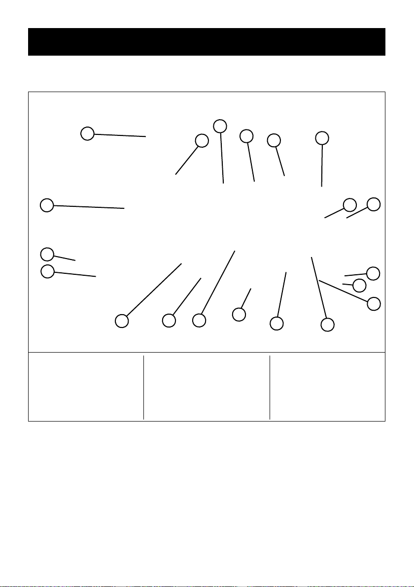
DESCRIPTION OF THE VEHICLE................................................................................................. 7
Side view ................................................................................................................................ 7
DESCRIPTION OF THE VEHICLE................................................................................................. 8
Controls and instruments ............................................................................................................. 8
CUSTOMER INFORMATION ........................................................................................................ 9
Vehicle identication number (VIN) ................................................................................................. 9
INSTRUMENTS AND CONTROLS .............................................................................................. 10
Ignition switch......................................................................................................................... 10
Instrument cluster .................................................................................................................... 10
Left handlebar switch ................................................................................................................ 11
Right handlebar switch .............................................................................................................. 11
Front and rear brake levers......................................................................................................... 11
Fuel ller cap.......................................................................................................................... 11
Fuel..................................................................................................................................... 12
Kickstarter ............................................................................................................................. 12
Seat..................................................................................................................................... 12
Storage compartment ............................................................................................................... 12
Helmet and luggage hooks ......................................................................................................... 13
Side stand ............................................................................................................................. 13
Main stand............................................................................................................................. 13
Combined brake system (CBS) (Only 125 cm³ Models)...................................................................... 13
PRE-OPERATION CHECKS....................................................................................................... 14
Checklist before setting o ......................................................................................................... 14
DRIVING OPERATION.............................................................................................................. 15
Starting the engine................................................................................................................... 15
Drive o ................................................................................................................................ 15
Acceleration / Deceleration ......................................................................................................... 15
Braking................................................................................................................................. 16
Parking................................................................................................................................. 16
Initial maintenance ................................................................................................................... 16
REGULAR MAINTENANCE AND MINOR REPAIRS........................................................................ 17
Tool kit ................................................................................................................................. 17
Battery cover.......................................................................................................................... 17
Spark plug ............................................................................................................................. 17
Engine oil .............................................................................................................................. 18
Transmission oil ...................................................................................................................... 18
Air lter................................................................................................................................. 19
ECU .................................................................................................................................... 19
Throttle cable clearance ............................................................................................................ 20
Tyres ................................................................................................................................... 20
Rims .................................................................................................................................... 21
Brake lever clearance ............................................................................................................... 21
Brake pads ........................................................................................................................... 21
Brake uid ............................................................................................................................. 21
Bowden cables ....................................................................................................................... 22
Throttle grip and throttle cable ..................................................................................................... 22
Lubricate brake lever ................................................................................................................ 22
Side and main stand................................................................................................................. 22
Telescopic fork ....................................................................................................................... 23
Steering ................................................................................................................................ 23
Wheel bearing ........................................................................................................................ 23
Battery ................................................................................................................................. 23
Fuses................................................................................................................................... 24
Lighting ................................................................................................................................ 24
TABLE OF CONTENTS