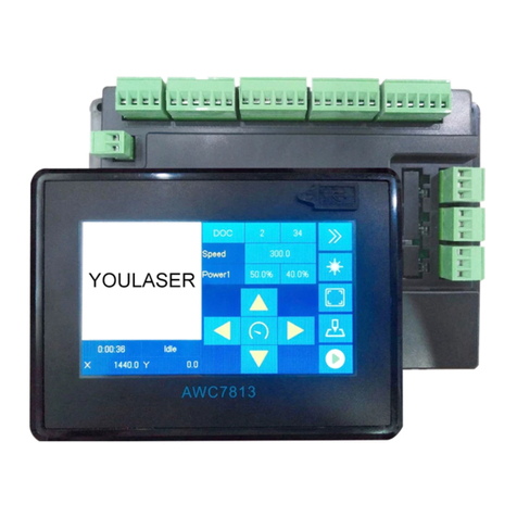
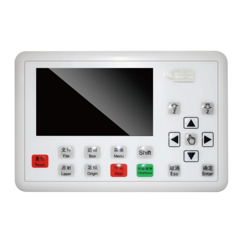
Trocen TC-6832 User manual

TC-
6832 Montion controller
Operation manual of main
6832 Montion controller
Operation manual of main
Vibration knife motion
controller series
6832 Montion controller
Operation manual of main
board
Vibration knife motion
controller series
RV 1.4

WWW.AWC608.COM
C
opyright notice
Shenzhen TROCEN automation technology co., LTD. (hereinafter
referred to as TROCEN) reserves the right to modify the products
and product specifications in this manual without prior notice.
TROCEN
shall not
incidental or consequential loss or liability caused by improper use
of this manual or product.
TROCEN has the patent right, copyright and other intellectual
property rights of the product and its software. With
authorization, the product and its related parts shall not be copied,
manufactured, processed or used directly or indirectly.
Machines in motion are dangerous. It is the
responsibility of the user to design effective error
handling and safety protec
use of the machine. We shall not be liable for any
incidental or consequential damages.
Contact us
Shenzhen TROCEN automation technology co., LTD.
Address: 1st floor, building 4, zhiheng industrial park, nanshan
district, shenzh
en city, guangdong province
TEL:0755-
27958262
FAX:0755-
27447913
EMAIL:
qiancheng@sztrocen.com
WEB:
www.sztrocen.com/www. awc608.com
Foreword
Motion controller user manual
opyright notice
Shenzhen TROCEN automation technology co., LTD. (hereinafter
referred to as TROCEN) reserves the right to modify the products
and product specifications in this manual without prior notice.
shall not
be liable for any direct, indirect, special,
incidental or consequential loss or liability caused by improper use
of this manual or product.
TROCEN has the patent right, copyright and other intellectual
property rights of the product and its software. With
authorization, the product and its related parts shall not be copied,
manufactured, processed or used directly or indirectly.
Machines in motion are dangerous. It is the
responsibility of the user to design effective error
handling and safety protec
tion mechanisms during the
use of the machine. We shall not be liable for any
incidental or consequential damages.
Shenzhen TROCEN automation technology co., LTD.
Address: 1st floor, building 4, zhiheng industrial park, nanshan
en city, guangdong province
27958262
27447913
-608
qiancheng@sztrocen.com
www.sztrocen.com/www. awc608.com
TC-6832
Motion controller user manual
1
Shenzhen TROCEN automation technology co., LTD. (hereinafter
referred to as TROCEN) reserves the right to modify the products
and product specifications in this manual without prior notice.
be liable for any direct, indirect, special,
incidental or consequential loss or liability caused by improper use
TROCEN has the patent right, copyright and other intellectual
property rights of the product and its software. With
out
authorization, the product and its related parts shall not be copied,
Machines in motion are dangerous. It is the
responsibility of the user to design effective error
tion mechanisms during the
use of the machine. We shall not be liable for any
Shenzhen TROCEN automation technology co., LTD.
Address: 1st floor, building 4, zhiheng industrial park, nanshan

WWW.AWC608.COM
Thank you for choosing gancheng motion controller.
In order to repay our customers, we will provide you with
motion controller, perfect after
support to help you complete the production of the equipment.
More information on TROCEN products
The company's website is
You can learn
more about the company and products on our
website, including: company profile, product introduction, technical
support and the latest product release.
You can also contact us at 0755
about the company and its products.
Techni
cal support and after
You can obtain our technical support and after
through the following ways:
Email:
qiancheng@sztrocen.com
TEL:0755-
27958262
To: floor 1, building 4, zhiheng industrial park, nanshan district,
shenzhen city, g
uangdong province
Shenzhen TROCEN automation technology co. LTD
Zip code:518100
Application
The user can understand the basic operation of the tc
card by reading this operation instruction.
Use object
This specification is suitable for
Motion controller user manual
Thank you for choosing gancheng motion controller.
In order to repay our customers, we will provide you with
motion controller, perfect after
-
sales service and efficient technical
support to help you complete the production of the equipment.
More information on TROCEN products
The company's website is
www.sztrocen.com/www. awc608.com.
more about the company and products on our
website, including: company profile, product introduction, technical
support and the latest product release.
You can also contact us at 0755
-
27958262 for more information
about the company and its products.
cal support and after
-
sales service
You can obtain our technical support and after
-
sales service
through the following ways:
qiancheng@sztrocen.com
27958262
To: floor 1, building 4, zhiheng industrial park, nanshan district,
uangdong province
Shenzhen TROCEN automation technology co. LTD
The user can understand the basic operation of the tc
-
6832 control
card by reading this operation instruction.
This specification is suitable for
engineers who have a certain
TC-6832
Motion controller user manual
2
In order to repay our customers, we will provide you with
first-class
sales service and efficient technical
support to help you complete the production of the equipment.
www.sztrocen.com/www. awc608.com.
more about the company and products on our
website, including: company profile, product introduction, technical
27958262 for more information
sales service
sales service
To: floor 1, building 4, zhiheng industrial park, nanshan district,
6832 control
engineers who have a certain

WWW.AWC608.COM
understanding of mechanical automation operation such as
vibrating knife.
Main content
The basic operation and use of TC
detail.
Related Documents
《TroCutCAD I
nstructions
1.2
Explanation of terms and abbreviations
1.3 Open box
................................
1.4
Panel appearance
1.5
Panel appearance and size drawing
1.5.1
Baseplate appearance and port
1.5.2 Port Instruction
1.5.2.1
Baseplate power port
1.
Product Introduction
1.1
system introduction
Tc-
6832 motion controller is a vibration cutting motion control
system developed by shenzhen TROCEN
co., LTD. TC -
6832 motion controller based on TC
original function, for the touch screen, increase the spindle cutting
indentation, V groove cutting, the press pulley, and other functions,
support double head, three h
the technological requirements, higher requirements for equipment
Motion controller user manual
understanding of mechanical automation operation such as
The basic operation and use of TC
-
6832 panel are introduced in
Related Documents
nstructions
》
Catalogue
Explanation of terms and abbreviations
................................
................................
................................
................................
Panel appearance
................................................................
........................
Panel appearance and size drawing
................................
.........................
Baseplate appearance and port
................................
1.5.2 Port Instruction
................................
................................
Baseplate power port
................................
................................
Product Introduction
system introduction
6832 motion controller is a vibration cutting motion control
system developed by shenzhen TROCEN
automation technology
6832 motion controller based on TC
-
6828 pro the
original function, for the touch screen, increase the spindle cutting
indentation, V groove cutting, the press pulley, and other functions,
support double head, three h
ead at the same time, the main meet
the technological requirements, higher requirements for equipment
TC-6832
Motion controller user manual
3
understanding of mechanical automation operation such as
6832 panel are introduced in
................................
.................... 5
................................
........ 5
........................
7
.........................
9
................................
...................... 9
................................
................. 10
................................
.. 10
6832 motion controller is a vibration cutting motion control
automation technology
6828 pro the
original function, for the touch screen, increase the spindle cutting
indentation, V groove cutting, the press pulley, and other functions,
ead at the same time, the main meet
the technological requirements, higher requirements for equipment

WWW.AWC608.COM
function more complex blade cutting production requirements and
develop a high-
end type vibration knife cutting motion controller.
The system is used by t
controller of the lower computer, which can greatly improve the
production efficiency and reduce the production cost.
The upper computer software of this system, namely TroCutCAD
software, has the following charac
friendly interface
operation
Support
CorelDraw
software
SupportAI
UD6 etc
formatted file
Simple drawing function
Automatic layout and path optimizatio
The motion controller of the lower plane of this system has the
following characteristics:
high-
speed DSP master control chip, faster operation
speed, more advanced motion algorithm, better effect
7 inch TFT LCD touch screen, more intuitive interface,
e
asier operation
all-
optical coupling isolates external electromagnetic
interference, making the system more stable and
reliable
Motion controller user manual
function more complex blade cutting production requirements and
end type vibration knife cutting motion controller.
The system is used by t
he upper computer software with the motion
controller of the lower computer, which can greatly improve the
production efficiency and reduce the production cost.
The upper computer software of this system, namely TroCutCAD
software, has the following charac
teristics:
friendly interface
,powerful ,
Intuitive and convenient
operation
CorelDraw
、Auto CAD etc
professional drawing
、PLT、DXF、SVG、PDF、NC、
DST
formatted file
Simple drawing function
Automatic layout and path optimizatio
n
The motion controller of the lower plane of this system has the
following characteristics:
speed DSP master control chip, faster operation
speed, more advanced motion algorithm, better effect
7 inch TFT LCD touch screen, more intuitive interface,
asier operation
optical coupling isolates external electromagnetic
interference, making the system more stable and
TC-6832
Motion controller user manual
4
function more complex blade cutting production requirements and
end type vibration knife cutting motion controller.
he upper computer software with the motion
controller of the lower computer, which can greatly improve the
The upper computer software of this system, namely TroCutCAD
Intuitive and convenient
professional drawing
DST
、DSB、
The motion controller of the lower plane of this system has the
speed DSP master control chip, faster operation
speed, more advanced motion algorithm, better effect
7 inch TFT LCD touch screen, more intuitive interface,
optical coupling isolates external electromagnetic
interference, making the system more stable and

WWW.AWC608.COM
support network, USB, U disk and other fast file reading
and writing
Support multi
efficienc
y
1.2
Explanation of terms and abbreviations
1-2-1
Explanation of terms and abbreviations
Terms/abbreviations
uppercomputer
software
TFT touch screen
The LCD panel
The control panel
Panel (main board)
Base plate (terminal
board)
system hardware
1.3 Open box
After receiving the products, please c
Motion controller user manual
support network, USB, U disk and other fast file reading
and writing
Support multi
-
working together, can double the
y
Explanation of terms and abbreviations
Explanation of terms and abbreviations
Terms/abbreviations
explanation
TroCutCAD
software is a special
supporting software for TROCEN knife
cutting motion controller
Refers to the 7 inch TFT color LCD touch
control panel. The panel is used for specific
display and control operations, and is an
important part of the system.
Base plate (terminal
The
baseplate is a control panel that
integrates signal input and output control
and motor driver connection.
system of visible physical objects,
including: panel, terminal board, wire, etc.
After receiving the products, please c
onfirm whether the
TC-6832
Motion controller user manual
5
support network, USB, U disk and other fast file reading
working together, can double the
Explanation of terms and abbreviations
software is a special
supporting software for TROCEN knife
Refers to the 7 inch TFT color LCD touch
control panel. The panel is used for specific
display and control operations, and is an
baseplate is a control panel that
integrates signal input and output control
system of visible physical objects,
including: panel, terminal board, wire, etc.
onfirm whether the

WWW.AWC608.COM
products and accessories are complete. If they are missing, please
contact the after-
sales service of shenzhen TRCEN automation co.,
LTD.
name
panel
baseboard
USB
cable(3m)
Net cable(5m)
Motion controller user manual
products and accessories are complete. If they are missing, please
sales service of shenzhen TRCEN automation co.,
1-3-1 product list
appearance
describtion
TC-6832
mainboard
TC-
6832
(
wiring board
Connect the panel to
the computer via USB.
Network connection
between panel and
computer.
TC-6832
Motion controller user manual
6
products and accessories are complete. If they are missing, please
sales service of shenzhen TRCEN automation co.,
describtion
mainboard
6832
baseboard
wiring board
)
Connect the panel to
the computer via USB.
Network connection
between panel and

WWW.AWC608.COM
DB15 cable
(2.5m)
USBextension
cable
(0.5m)
Network
extension
cable(0.5m)
DB9 线
(2.5m)
1.4
Panel appearance
system panel is designed with
Pic 1-4-1
Panel appearance and size drawing
Motion controller user manual
A DB15 line is attached
with the box to
the CN1 and port of the
panel and baseplate.
USB
extension cable
Network extension
cable
随箱附带
1
连接面板和底板的
端口。
Panel appearance
system panel is designed with
a display screen, soft buttons and a
usb jack.
Panel appearance and size drawing
TC-6832
Motion controller user manual
7
A DB15 line is attached
with the box to
connect
the CN1 and port of the
panel and baseplate.
extension cable
Network extension
1
条DB9 线,
连接面板和底板的
CN2
a display screen, soft buttons and a
Panel appearance and size drawing

WWW.AWC608.COM
Motion controller user manual
TC-6832
Motion controller user manual
8

WWW.AWC608.COM
1.5
Panel appearance and size drawing
The base plate is used for the connection between the panel and
other parts of the machine. Include
Connected
Detection of motion axis limit signal
Input signal detection
IO
Control signal and output of corresponding power
supply
1.5.1
Baseplate appearance and port
Pic 1-5-1
Baseplate appearance display and dimension
Motion controller user manual
Panel appearance and size drawing
The base plate is used for the connection between the panel and
other parts of the machine. Include
Connected
motor driver
Detection of motion axis limit signal
Input signal detection
Control signal and output of corresponding power
Baseplate appearance and port
Baseplate appearance display and dimension
drawing
TC-6832
Motion controller user manual
9
The base plate is used for the connection between the panel and
Control signal and output of corresponding power
Baseplate appearance display and dimension

WWW.AWC608.COM
1.5.2 Port Instruction
1.5.2.1
Baseplate power port
The baseplate power port is used to supply power to the
baseplateand the panel. When connecting, please pay attention to
the positive and negative terminals.
1-5-1
Baseplate power port description
Pin Name
1 +24V
positive pole
2 GND
negative pole
Motion controller user manual
1.5.2 Port Instruction
Baseplate power port
The baseplate power port is used to supply power to the
baseplateand the panel. When connecting, please pay attention to
the positive and negative terminals.
Baseplate power port description
Description
positive pole
negative pole
TC-6832
Motion controller user manual
10
The baseplate power port is used to supply power to the
baseplateand the panel. When connecting, please pay attention to

WWW.AWC608.COM
1.5.2.2
The panel is connected to the baseplate
The panel is connected with the baseplate by 2 serial port lines,
and the corresponding port can be connected
1-5-2
Description of connection ports between panel and
Port
name
Description
CN1
Connect the baseplate to the CN1 port of the panel
with the DB15 line.
CN2
Connect the baseplate to the CN2 port of the panel
with DB9 line, connect two heads, optional
1.5.2.3
Signal input port
The baseplate provides
the acquisition of input signals.
Table1-5-
3 Wiring Board Signal Input Port Instruction
PIN
Name
Instruction
1 1 IN1
Open protection (input).
This feature must be enabled in the panel to be
effective.
2 IN2
Foot switch signal or pause signal(input). This
feature must be enabled in the panel to be
Motion controller user manual
The panel is connected to the baseplate
The panel is connected with the baseplate by 2 serial port lines,
and the corresponding port can be connected
Description of connection ports between panel and
Description
Connect the baseplate to the CN1 port of the panel
with the DB15 line.
Connect the baseplate to the CN2 port of the panel
with DB9 line, connect two heads, optional
Signal input port
The baseplate provides
multiple sets of input signal terminals for
the acquisition of input signals.
3 Wiring Board Signal Input Port Instruction
Instruction
Open protection (input).
This feature must be enabled in the panel to be
effective.
Foot switch signal or pause signal(input). This
feature must be enabled in the panel to be
TC-6832
Motion controller user manual
11
The panel is connected with the baseplate by 2 serial port lines,
Description of connection ports between panel and
baseplat
Connect the baseplate to the CN1 port of the panel
Connect the baseplate to the CN2 port of the panel
with DB9 line, connect two heads, optional
multiple sets of input signal terminals for
3 Wiring Board Signal Input Port Instruction
This feature must be enabled in the panel to be
Foot switch signal or pause signal(input). This
feature must be enabled in the panel to be

WWW.AWC608.COM
effective.
Foot switch function includes the function of start
work and pause or continue when machine is
working.
The panel pause key only has the function of
p
ause work or continue to work.
Setting method: turn on the foot switch, no matter
whether the pause function is on or off, there is no
effect;Stop function,must first turn off the foot
switch function, panel pause key can be used.
3 IN3
Servo error check
This feature must be enabled in the panel to be
effective.
4 IN4
Servo error check 2 (input).
This feature must be enabled in the panel to be
effective.
5 GND
Power ground.
2 1 IN5
Servo error check 3 (input).
This feature must be
effective.
2 IN6
Servo error check 4 (input).
This feature must be enabled in the panel to be
effective.
3 IN7
Reserved (input).
4 IN8
Reserved (input).
5 GND
Power ground.
Motion controller user manual
effective.
Foot switch function includes the function of start
work and pause or continue when machine is
working.
The panel pause key only has the function of
ause work or continue to work.
Setting method: turn on the foot switch, no matter
whether the pause function is on or off, there is no
effect;Stop function,must first turn off the foot
switch function, panel pause key can be used.
Servo error check
1 (input).
This feature must be enabled in the panel to be
effective.
Servo error check 2 (input).
This feature must be enabled in the panel to be
effective.
Power ground.
Servo error check 3 (input).
This feature must be
enabled in the panel to be
effective.
Servo error check 4 (input).
This feature must be enabled in the panel to be
effective.
Reserved (input).
Reserved (input).
Power ground.
TC-6832
Motion controller user manual
12
Foot switch function includes the function of start
work and pause or continue when machine is
The panel pause key only has the function of
Setting method: turn on the foot switch, no matter
whether the pause function is on or off, there is no
effect;Stop function,must first turn off the foot
switch function, panel pause key can be used.
This feature must be enabled in the panel to be
This feature must be enabled in the panel to be
enabled in the panel to be
This feature must be enabled in the panel to be

WWW.AWC608.COM
3 1 X-
The origin limit of the X axis. When
moves to the minimum coordinate position (zero
position), the limit sensor inputs signal.
2 Y-
The origin limit of the Y axis. When the Y axis
moves to the minimum coordinate position (zero
position), the limit sensor inputs signal.
3 X+
The hard limit of X axis. When the X axis moves to
the maximum coordinate position, the limit sensor
inputs signal.
4 Y+
The hard limit of Y axis. When the Y axis moves to
the maximum coordinate position, the limit sensor
inputs signal.
5 GND
Power gr
4 1 Z-
The origin limit of the Z axis. When the Z axis
moves to the minimum coordinate position (zero
position), the limit sensor inputs signal.
2 U-
The origin limit of the U axis. When the U axis
moves to the minimum coordinate position (zero
position), the limit sensor inputs signal.
3 UD1
The origin limit of the UD1 axis. When the UD1 axis
moves to the minimum coordinate position (zero
position), the limit sensor inputs signal.
4 UD2
The origin limit of the UD2 axis. When the UD2 axis
moves to the minimum coordinate position (zero
positi
5 GND
Power ground.
Motion controller user manual
The origin limit of the X axis. When
the X axis
moves to the minimum coordinate position (zero
position), the limit sensor inputs signal.
The origin limit of the Y axis. When the Y axis
moves to the minimum coordinate position (zero
position), the limit sensor inputs signal.
The hard limit of X axis. When the X axis moves to
the maximum coordinate position, the limit sensor
inputs signal.
The hard limit of Y axis. When the Y axis moves to
the maximum coordinate position, the limit sensor
inputs signal.
Power gr
ound.
The origin limit of the Z axis. When the Z axis
moves to the minimum coordinate position (zero
position), the limit sensor inputs signal.
The origin limit of the U axis. When the U axis
moves to the minimum coordinate position (zero
position), the limit sensor inputs signal.
The origin limit of the UD1 axis. When the UD1 axis
moves to the minimum coordinate position (zero
position), the limit sensor inputs signal.
The origin limit of the UD2 axis. When the UD2 axis
moves to the minimum coordinate position (zero
positi
on), the limit sensor inputs signal.
Power ground.
TC-6832
Motion controller user manual
13
the X axis
moves to the minimum coordinate position (zero
position), the limit sensor inputs signal.
The origin limit of the Y axis. When the Y axis
moves to the minimum coordinate position (zero
position), the limit sensor inputs signal.
The hard limit of X axis. When the X axis moves to
the maximum coordinate position, the limit sensor
The hard limit of Y axis. When the Y axis moves to
the maximum coordinate position, the limit sensor
The origin limit of the Z axis. When the Z axis
moves to the minimum coordinate position (zero
position), the limit sensor inputs signal.
The origin limit of the U axis. When the U axis
moves to the minimum coordinate position (zero
position), the limit sensor inputs signal.
The origin limit of the UD1 axis. When the UD1 axis
moves to the minimum coordinate position (zero
position), the limit sensor inputs signal.
The origin limit of the UD2 axis. When the UD2 axis
moves to the minimum coordinate position (zero
on), the limit sensor inputs signal.

WWW.AWC608.COM
5 1 R1-
The origin limit of the R1 axis. When the R1 axis
moves to the minimum coordinate position (zero
position), the limit sensor inputs signal.
2 R2-
The origin limit of the R2 axis. When
moves to the minimum coordinate position (zero
position), the limit sensor inputs signal.
3 N1
The origin limit of the N1 axis. When the N1 axis
moves to the minimum coordinate position (zero
position), the limit sensor inputs signal.
4 N2
The origin limit of the N2 axis. When the N2 axis
moves to the minimum coordinate position (zero
position), the limit sensor inputs signal.
5 GND
Power ground.
Note:
All input ports: Voltage 24v or 0v, need to open the function in the
panel, high and
low level can be optional.
Manufacturers recommend:axis origin, hardware limit switch: it is
recommended to choose NPN type, often open.Common sensors:
black line connect signal feet, blue line connect GND, brown line
connect 24v.
All input ports can be c
1.5.2.4 signal output end
Output voltage: 24v, effective at high voltage.Each outlet must be
connected to rated dc voltage 24V or more relay to use, not directly
connected to the load!
All outlets can output test inter
Motion controller user manual
The origin limit of the R1 axis. When the R1 axis
moves to the minimum coordinate position (zero
position), the limit sensor inputs signal.
The origin limit of the R2 axis. When
moves to the minimum coordinate position (zero
position), the limit sensor inputs signal.
The origin limit of the N1 axis. When the N1 axis
moves to the minimum coordinate position (zero
position), the limit sensor inputs signal.
The origin limit of the N2 axis. When the N2 axis
moves to the minimum coordinate position (zero
position), the limit sensor inputs signal.
Power ground.
All input ports: Voltage 24v or 0v, need to open the function in the
low level can be optional.
Manufacturers recommend:axis origin, hardware limit switch: it is
recommended to choose NPN type, often open.Common sensors:
black line connect signal feet, blue line connect GND, brown line
All input ports can be c
hecked in the panel's test interface.
1.5.2.4 signal output end
Output voltage: 24v, effective at high voltage.Each outlet must be
connected to rated dc voltage 24V or more relay to use, not directly
connected to the load!
All outlets can output test inter
face to test, respectively: one key to
TC-6832
Motion controller user manual
14
The origin limit of the R1 axis. When the R1 axis
moves to the minimum coordinate position (zero
position), the limit sensor inputs signal.
The origin limit of the R2 axis. When
the R2 axis
moves to the minimum coordinate position (zero
position), the limit sensor inputs signal.
The origin limit of the N1 axis. When the N1 axis
moves to the minimum coordinate position (zero
position), the limit sensor inputs signal.
The origin limit of the N2 axis. When the N2 axis
moves to the minimum coordinate position (zero
position), the limit sensor inputs signal.
All input ports: Voltage 24v or 0v, need to open the function in the
Manufacturers recommend:axis origin, hardware limit switch: it is
recommended to choose NPN type, often open.Common sensors:
black line connect signal feet, blue line connect GND, brown line
hecked in the panel's test interface.
Output voltage: 24v, effective at high voltage.Each outlet must be
connected to rated dc voltage 24V or more relay to use, not directly
face to test, respectively: one key to

WWW.AWC608.COM
open or close all OUT ports;Open or close all odd OUT ports with
one click;Open or close all even number OUT ports with one
click;Open or close each OUT port individually.
Table1-5-
4 Wiring Board Signal Output Port
Name
Instruction
OUT1
Head
OUT2
Head
OUT3
Head
OUT4
Clip Material
OUT5
Feeding
OUT6
Punch motor
OUT7
OUT8
Micro Punching
OUT9
Small Punching
OUT10
Big Punching
OUT11
V-
Punching
OUT12
Reserved
OUT13
Reserved
OUT14
Reserved
OUT15
Red indicating
Motion controller user manual
open or close all OUT ports;Open or close all odd OUT ports with
one click;Open or close all even number OUT ports with one
click;Open or close each OUT port individually.
4 Wiring Board Signal Output Port
Instruction
Instruction
Name
Instruction
Head
-1 Working
OUT18
Global adsorption
Head
-2 Working
OUT19
Adsorb 1
Head
-3 Working
OUT20
Adsorb 2
Clip Material
OUT21
Adsorb 3
Feeding
OUT22
Adsorb 4
Punch motor
works OUT23
Adsorb 5
pen OUT24
Adsorb 6
Micro Punching
OUT25
Adsorb 7
Small Punching
OUT26
Adsorb 8
Big Punching
OUT27
Adsorb 9
Punching
OUT28
Adsorb 10
Reserved
OUT29
Adsorb 11
Reserved
OUT30
Adsorb 12
Reserved
OUT31
dispensing
Red indicating
OUT32
Reserved
TC-6832
Motion controller user manual
15
open or close all OUT ports;Open or close all odd OUT ports with
one click;Open or close all even number OUT ports with one
Instruction
Instruction
Global adsorption
Adsorb 1
Adsorb 2
Adsorb 3
Adsorb 4
Adsorb 5
Adsorb 6
Adsorb 7
Adsorb 8
Adsorb 9
Adsorb 10
Adsorb 11
Adsorb 12
dispensing
Reserved

WWW.AWC608.COM
1.5.2.5 Wiring Board motor driver control port
The wiring board can provide the connection of up to 10 motor
drivers, the user can choose the step driver or the servo driver
according to the need.
The servo driver is more accurate than the step driver, the user can
choose the appropriate driver according to the use of the scene,
cutting precision requirements and
Table1-5-
5 Motor Driver connection Instruction
OUT16
Green indicating
OUT17
Yellow indicating
PI
N
Nam
e
Instruction
X_AXI
S
1 PUL-
Pulse Negative
2 PUL
+
Pulse Positive
3 DIR-
Negative Signal
Motion controller user manual
1.5.2.5 Wiring Board motor driver control port
The wiring board can provide the connection of up to 10 motor
drivers, the user can choose the step driver or the servo driver
according to the need.
The servo driver is more accurate than the step driver, the user can
choose the appropriate driver according to the use of the scene,
cutting precision requirements and
cost factors.
5 Motor Driver connection Instruction
light
Green indicating
light
Yellow indicating
light GND
Power ground.
Instruction
PI
N
Nam
e
Pulse Negative
Signal R1_AXI
S
(Rotat
e)
1 PUL-
Pulse Positive
Signal 2 PUL
+
Direction
Negative Signal
3 DIR-
TC-6832
Motion controller user manual
16
The wiring board can provide the connection of up to 10 motor
drivers, the user can choose the step driver or the servo driver
The servo driver is more accurate than the step driver, the user can
choose the appropriate driver according to the use of the scene,
5 Motor Driver connection Instruction
Power ground.
Instruction
Pulse
Negative
Signal
Pulse Positive
Signal
Direction
Negative
Signal

WWW.AWC608.COM
4 DIR+
Positive Signal
Y_AXI
S
1 PUL-
Pulse Negative
2 PUL
+
Pulse Positive
3 DIR-
Negative Signal
4 DIR+
Positive Signal
U_AXI
S
(Feed
ing)
1 PUL-
Pulse Negative
2 PUL
+
Pulse Positive
3 DIR-
Negative Signal
4 DIR+
Positive Signal
Z_AXI
S
1 PUL-
Pulse Negative
2 PUL
Pulse Positive
Motion controller user manual
Direction
Positive Signal
4 DIR
+
Pulse Negative
Signal
UD1_A
XIS
(Up-Do
wn)
1 PUL-
Pulse Positive
Signal
2 PUL
+
Direction
Negative Signal
3 DIR-
Direction
Positive Signal
4 DIR
+
Pulse Negative
Signal
R2_AXI
S
(Rotat
e)
1 PUL-
Pulse Positive
Signal
2 PUL
+
Direction
Negative Signal
3 DIR-
Direction
Positive Signal
4 DIR
+
Pulse Negative
Signal
UD2_A
XIS
(Up-Do
1 PUL-
Pulse Positive
2 PUL
TC-6832
Motion controller user manual
17
Direction
Positive Signal
Pulse
Negative
Signal
Pulse Positive
Signal
Direction
Negative
Signal
Direction
Positive Signal
Pulse
Negative
Signal
Pulse Positive
Signal
Direction
Negative
Signal
Direction
Positive Signal
Pulse
Negative
Signal
Pulse Positive

WWW.AWC608.COM
2. TroCutCAD Installation
You can go through
about installation and how
3.
Coordination System
In order to help the users to understand the relevant operation
instructions better, the coordinate system involved is described in
detail here. The translation axis is applicable to the cartesian
coordinate system (the two
The rotation axis is suitable for the rotation coordinate system.
3.1 Plane Coordinate
(Hea
d-3)
+
3 DIR-
Negative Signal
4 DIR+
Positive Signal
N1_AX
IS
(Rese
rved)
1 PUL-
Pulse Negative
2 PUL
+
Pulse Positive
3 DIR-
Negative Signal
4 DIR+
Positive Signal
Motion controller user manual
2. TroCutCAD Installation
You can go through
《TroCutCAD User Manual》
for more details
about installation and how
-to-use TroCutCAD.
Coordination System
In order to help the users to understand the relevant operation
instructions better, the coordinate system involved is described in
detail here. The translation axis is applicable to the cartesian
coordinate system (the two
-
dimensional plane coordinate sys
The rotation axis is suitable for the rotation coordinate system.
3.1 Plane Coordinate
Signal wn) +
Direction
Negative Signal
3 DIR-
Direction
Positive Signal
4 DIR
+
Pulse Negative
Signal
N2_AXI
S
(Rese
rved)
1 PUL-
Pulse Positive
Signal
2 PUL
+
Direction
Negative Signal
3 DIR-
Direction
Positive Signal
4 DIR
+
TC-6832
Motion controller user manual
18
for more details
In order to help the users to understand the relevant operation
instructions better, the coordinate system involved is described in
detail here. The translation axis is applicable to the cartesian
dimensional plane coordinate sys
tem).
The rotation axis is suitable for the rotation coordinate system.
Signal
Direction
Negative
Signal
Direction
Positive Signal
Pulse
Negative
Signal
Pulse Positive
Signal
Direction
Negative
Signal
Direction
Positive Signal

WWW.AWC608.COM
Origin
The same position as where limit switch is located in.
X+ Axis
The positive rotation that is the opposite direction away from limit
switch on X axis.
X- Axis
The negative rotation that is the opposite direction to X+.
Y+ Axis
The positive rotation that is the opposite direction away from limit
switch on Y axis.
Y- Axis
The negative rotation that is the opposite direction t
3.2 Rotation Coordinate
Origin
The point of cutting table mapping from center point for rotary axis.
Clockwise
Rotation from X+ direction to Y+. Coordinate value increases if axis
is rotating clockwise.
Counter-
Clockwise
Coordinate value decreases if axis is rotating counter
The origin will be changing depending on axis’s moving.TC
PLUS Motion Controller User Manual
Coordinate Value
The rotation coordinate value is the number of cycles, like 360
degree
for one cycle. If the axis rotates positively and the
coordinate value increases from 0 to 360, then the rotation
coordinate value will be reset to 0. If the axis rotates negatively and
Motion controller user manual
The same position as where limit switch is located in.
The positive rotation that is the opposite direction away from limit
The negative rotation that is the opposite direction to X+.
The positive rotation that is the opposite direction away from limit
The negative rotation that is the opposite direction t
o Y
-
3.2 Rotation Coordinate
The point of cutting table mapping from center point for rotary axis.
Rotation from X+ direction to Y+. Coordinate value increases if axis
is rotating clockwise.
Clockwise
Coordinate value decreases if axis is rotating counter
-
clockwise.
The origin will be changing depending on axis’s moving.TC
PLUS Motion Controller User Manual
Coordinate Value
The rotation coordinate value is the number of cycles, like 360
for one cycle. If the axis rotates positively and the
coordinate value increases from 0 to 360, then the rotation
coordinate value will be reset to 0. If the axis rotates negatively and
TC-6832
Motion controller user manual
19
The positive rotation that is the opposite direction away from limit
The negative rotation that is the opposite direction to X+.
The positive rotation that is the opposite direction away from limit
-
.
The point of cutting table mapping from center point for rotary axis.
Rotation from X+ direction to Y+. Coordinate value increases if axis
clockwise.
The origin will be changing depending on axis’s moving.TC
-6828
The rotation coordinate value is the number of cycles, like 360
for one cycle. If the axis rotates positively and the
coordinate value increases from 0 to 360, then the rotation
coordinate value will be reset to 0. If the axis rotates negatively and
Table of contents
Other Trocen Security Sensor manuals
Popular Security Sensor manuals by other brands
Inficon
Inficon HLD6000 installation manual

Crewsaver
Crewsaver CREWFIT 165 SPORT owner's manual

Honeywell
Honeywell 14506873-001 installation instructions
STEINEL
STEINEL Multisensor True Presence DALI-2 IPD manual
Allen-Bradley
Allen-Bradley GuardShield Micro 400 installation instructions
Clare Controls
Clare Controls ClareOne CLR-C1-PIR Installation sheet
