TRONZADORAS MG TL-600-A User manual
TL-600-A
MADE IN SPAIN
2011 EDITION
(VERSION 1.0)

2
TL
-
6
00
-
A
TABLE OF CONTENTS _ _ >>>
1. INTRODUCTION.
1.1. LEGISLATION APPLICABLE TO THE PLANNING AND CONSTRUCTION OF THE MACHINE.
2. GENERAL MACHINE DATA.
2.1. MACHINE IDENTIFICATION DATA.
2.2. TECHNICAL DATA.
2.3. ELECTRICAL DATA.
2.4. NOISE LEVEL.
3. INDICATIONS REGARDING TRANSPORT AND STORAGE.
4. INSTRUCTIONS FOR ANCJORING AND SERVICE START-UP.
4.1. ANCHORING INSTRUCTIONS.
4.2. POWER SUPPLY CONNECTION.
4.3. INSTRUCTION REGARDING BLADE INSTALLATION.
4.4. CUTTING COOLANT.
4.5. PNEUMATIC OIL.
5. INSTRUCTIONS FOR USE.
5.1. PROPER AND IMPROPER USE.
5.2. FUNCTION OF THE OPERATING MECHANISMS.
5.3. INSTRUCTIONS FOR THE ADJUSTMENT OF THE DIGITAL DEGREES.
5.4. GENERAL RULES AND SAFETY CHECKS.
6. RECOMENDATIONS AND MAINTENANCE.
6.1. TYPE AND FRECUENCY OF INSPECTIONS.
6.2. QUALIFIED PERSONNEL FOR MAINTENANCE AND REPAIR WORK.
6.3. MANUFECTURER RECOMENDATIONS.
7. DRAWIINGS AND SCHEMATICS.
7.1. GENERAL SCHEMATIC.
7.2. POWER CIRCUIT.
7.3. PNEUMATIC SCHEMATIC.
7.4. EXPLODED VIEW CAST IRON TABLE AND DISC ASSEMBLY.
7.5. EXPLODED VIEW ROCKER ASSEMBLY.
7.6. EXPLODED VIEW TURRET ASSEMBLY.
7.7. EXPLODED VIEW SHEET METAL BASE.
7.8. EXPLODED VIEW PROTECTIVE SHIELD.

3
TL
-
6
00
-
A
1. INTRODUCTION. >>>
This instruction manual has been made in compliance with the requirements of the Legislation
according to the Machine directive 2006/42/CEE and its subsequent amendments.
The instruction manual represents an integral part of the machine. It must be consulted
before, during and after the machine is put into service, as well as whenever it is considered
necessary, thereby respecting the content in each and every one of its parts.
This is the only way in which the fundamental objectives that have been established on the
basis of this manual will be achieved, such as accident prevention and making optimal use of the
machine features.
Within the framework of this manual, all aspects regarding safety and accident prevention on
the job while using the machine have been considered in every detail, herein highlighting the
information that is of greatest interest to the user.
ATTENTIÓN
Before installing the machine, read this manual carefully. The manual must be kept
throughout the life of the machine, so that it is easy to find if necessary. In the event that the
used machine is sold, the machine shall be sold together with this manual. In the event that
the machine is scrapped, the identification plate and any other document supplied with the
same must be destroyed.
1.1 Normativa aplicada en el proyecto y en la construcción.
EN-12100-1 Machine Safety. Basic concepts, general design principles.
EN-12100-2 Machine Safety. Basic concepts, general design principles.
EN-13857 Safety distances to prevent dangerous zones from being reached by the upper
extremities.
EN-60204/1 Electrical equipment of industrial machines.
EN-13850 Machine safety; emergency stop equipment.
and is in conformity with the Essential Requirements of the Directives:
2006/42/CEE on “Machine Safety.”
73/23/CEE on “Safety of Electrical Material.”
93/68/CEE on the CE Marking (amendment)
2004/108/CEE on “Electromagnetic Compatibility.”
4
TL
-
6
00
-
A
2. GENERAL INFORMATION. >>>
TRONZADORAS MG S.A.
Pol ind. FONT DE LA PARERA, s/n
08430 LA ROCA DEL VALLES
BARCELONA (ESPAÑA)
lfs: 34 93 842 41 60……Fax: 34 93 842 41 28
Web: www.tronzadorasmg.com
E-mail: [email protected]
2.1. Machine identification data.
Model:
..……………………………………………….
TL-600-A
Serial number:
……………………………………
Manufacturing year:
…………………………………
NOTE
In order to request spare parts, whether covered by the warranty or not, always indicate
the model and serial number of the machine, as well as the name of the part and the code that
appear in the last chapter of the parts exploded views.
2.2. Technical data.
Characteristic Dimension
Three phase motor 4 HP, 220/380V
Motor speed 3000 RPM
Interior Ø of blade 50 mm
Maximum Ø of saw blade Ø600 x Ø50 x 4,5 mm
Cutting speed 55 m/seg
Turn 90º RIGHT - 60º LEFT
Working pressure 7 atm
Pneumatic hold-down clamps 2 vertical +2 horizontal
Lubrication system Pneumatic, by sprayer
Dimensions 1300 x 1220x 1635
Weight 500 Kgs
5
TL
-
6
00
-
A
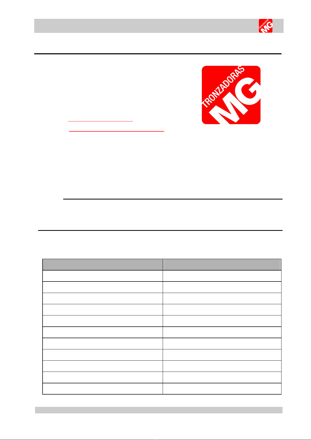
2.3. Dimensions of the machine.
770mm
934mm
ANCHO MAX: 1249mm
911mm
1636mm
850mm
905mm
1050mm
1301mm
1636mm
1052mm
2.4. Cutting capacity.
0
50
100
150
200
10
20
30
40
60
70
80
90
110
120
130
140
160
170
180
190
210
220
230
240
260
270
280
290
250
300
310
320
0
50
100
150
200
250
240
230
220
210
190
180
170
160
140
130
120
110
90
80
70
60
40
30
20
10
90º
45º
22.5º
10
20
30
40
60
70
50
TURRET
80
90
100
110
120
130
140
150
160
170
180
190
205
6
TL
-
6
00
-
A
2.5. Electrical data.
Power supply Motor power Total
220 V Three phase 3 kW / 4 HP 12 A
380 V Three phase 3 kW / 4 HP 7 A
2.6. Noise level.
At a distance of 60 cm RUNNING OFF-LOAD Leq 80 Db (A)
MACHINING A 70x50 PROFILE Leq 120 Db (A)
ATTENTION
When working with the machine, use individual hearing protection equipment.
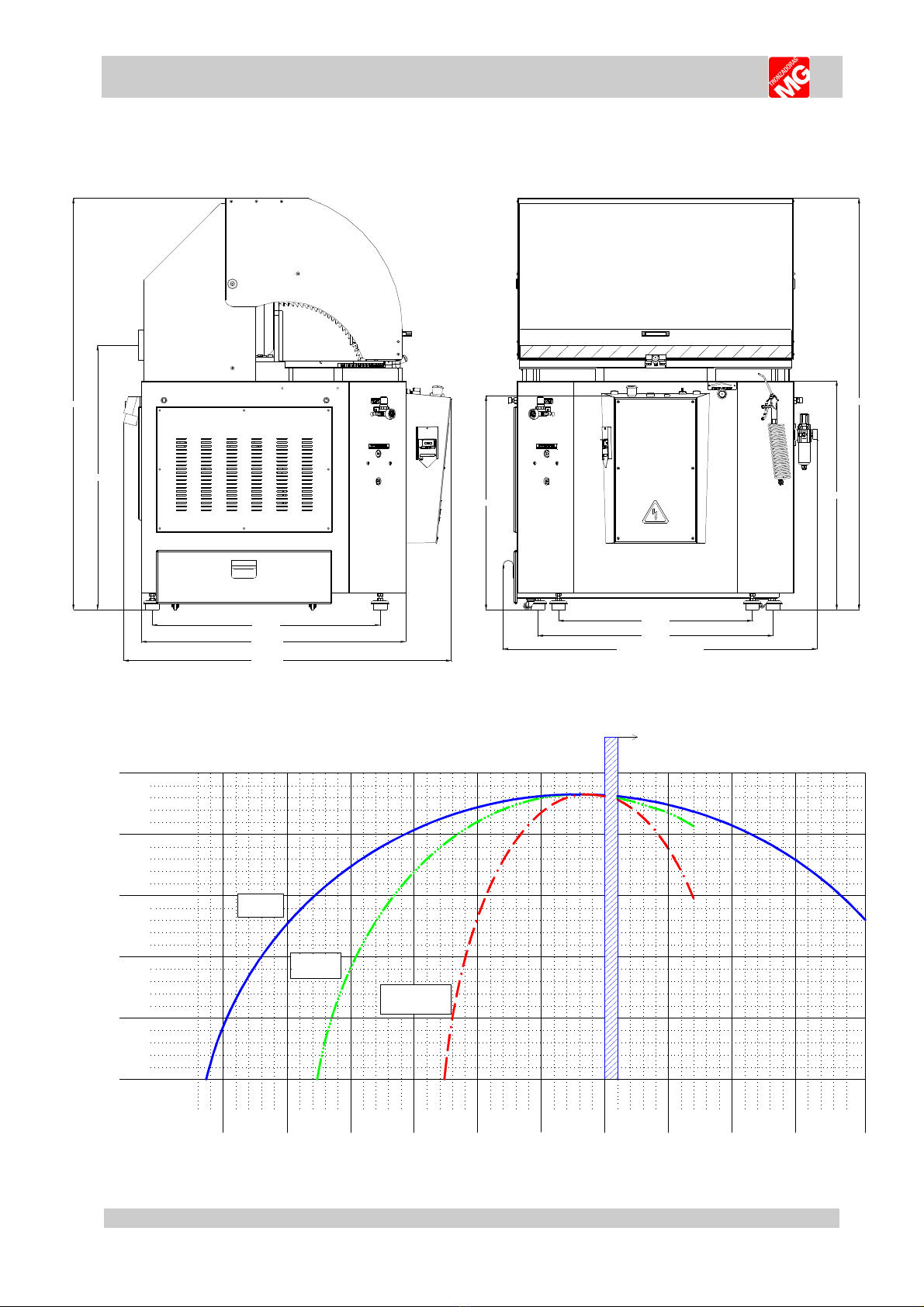
3. INDICATIONS REGARDING TRANSPORT AND STORAGE. >>>
Transp rt with a f rklift Transp rt with a crane bridge
7
TL
-
6
00
-
A
Recommendations:
•Store in the vertical position. Do not stack.
•If the machine remains stored for a long period of time, periodically lubricate.
•Do not expose to the elements.
•The packaging is made of properly designed and sized wood, and it is also supplied
wrapped in plastic.
CAUTION
Do not improperly dispose of the packaging. Send this material to be recycled or disposed
of in accordance with all legislation in force.
4. INSTRUCTIONS FOR ANCHORING AND SERVICE START-UP. >>>
4.1. Instructions for anchoring.
Ensure that the machine has not suffered any damage during transport by making an initial
visual inspection. If damage is observed, advise the manufacturer immediately.
The machine must be installed on a firm and level surface in order to thus reduce vibrations
during operation and so that the machine operates within the parameters established by the
manufacturer.
Verify that the power supply voltage corresponds to the voltage indicated on the specifications
plate of the machine. Connect the cable to the power supply using a plug that is appropriate for the
characteristics of the same, thereby respecting the colour codes. Once joined the machine, to verify
the sense of rotation; if the rotation is not the suitable one, to change two phases of the plug.
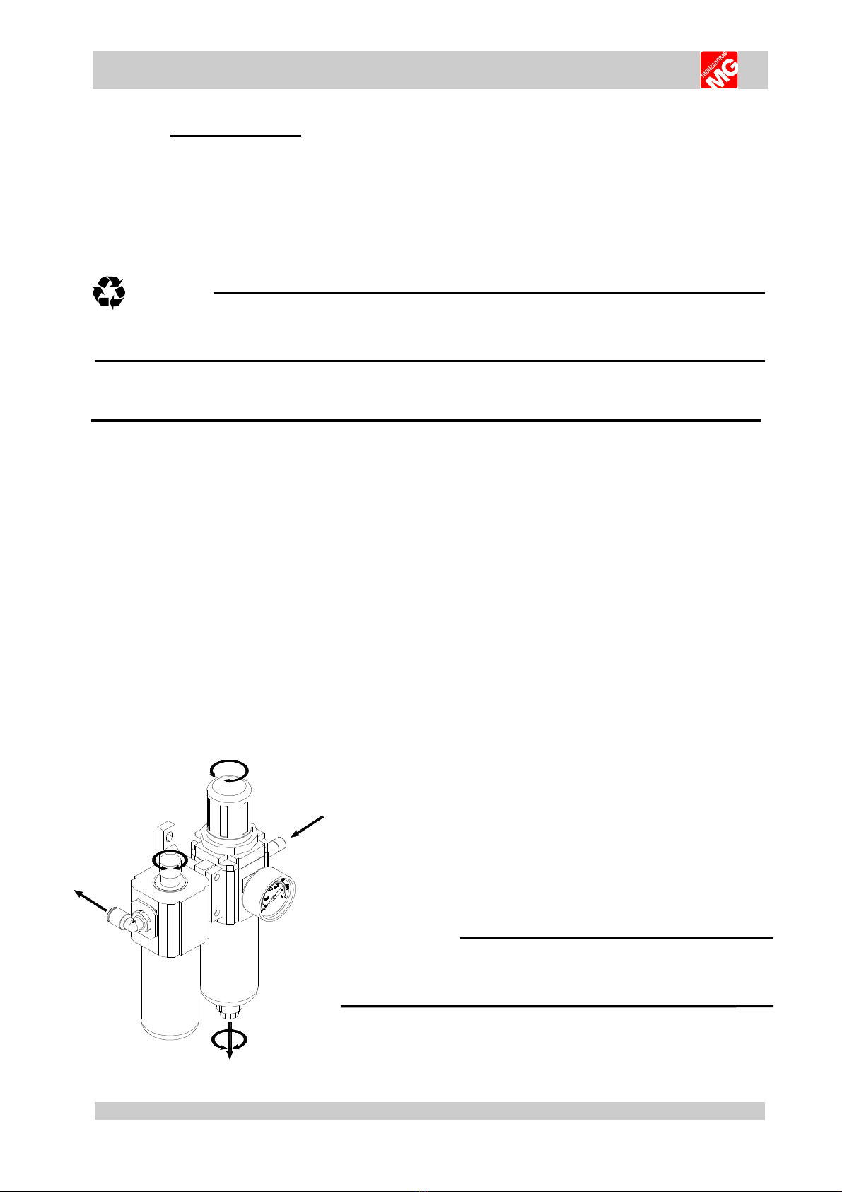
4.2. Reglaje de reguladores de presión.
The machine has in the entry of the pneumatic circuit of a
regulatory lubricating filter. The mission of this one is regular the
pressure of air inlet in the machine between 6-7bar and lubricant
the air that enters the machine not to damage the pistons and
mobile elements.
ATTENTION
The pneumatic working pressure for vertical
clamps must be between 6 and 7 atm

8
TL
-
6
00
-
A
ATTENTION
The pneumatic working
pressure for horizontal clamps
must be between 3 and 4 atm
4.3.
Instructions regarding blade installation.
To place the machine to 22,5 º
towards the left side and to fix with the
automatic anchorage, there slackens the
disc (4) with the bar and the fixed key sent
with the machine. To do it with the bar and
the fixed key sent with the machine. To place
the new disc (4) in the axis (3), fitting it into
the screw of dragging (2) mounted in the
axis. To place the socket-pan (5) and to fix it
by means of the bar, to press the nut (6) as
Indian the figure. In order to accede to the
disc using the lateral door of the machine, to
make sure that the sense of the teeth of the
mountain range agrees with the direction of
rotation of the motor. Asegúrese also that
the diameter of the disc is the adapted one
for this machine (600mm).
ATTENTION
The blade nut is reverse threaded.
DANGER
After changing the blade, put the sheet metal front back on.
1234
56
9
TL
-
6
00
-
A
4.4. Cutting coolant.
In order to fill the machine with cutting coolant, open the reservoir and fill with PURE, NON-
EMULSIFIABLE CUTTING OIL (VISCOSITY ISO VG 16-32 cST 40ºC)
4.5. Pneumatic oil.
Both the oleo-pneumatic converters and the filter group lubricator must be filled with ISO VG
16 VISCOSITY PNEUMATIC OIL. If none is available, use hydraulic oil 16.
5. INSTRUCTIONS FOR USE. >>>
5.1. Proper and improper use.
This is a semiautomatic cut-off machine especially designed for cutting aluminium profiles.
The use of the machine for cutting other materials is hereby prohibited. Such use may cause
damage to the machine and put the health and safety of the worker at risk.
DANGER
We are not responsible for any possible accident caused by the failure to
comply with the aforementioned.
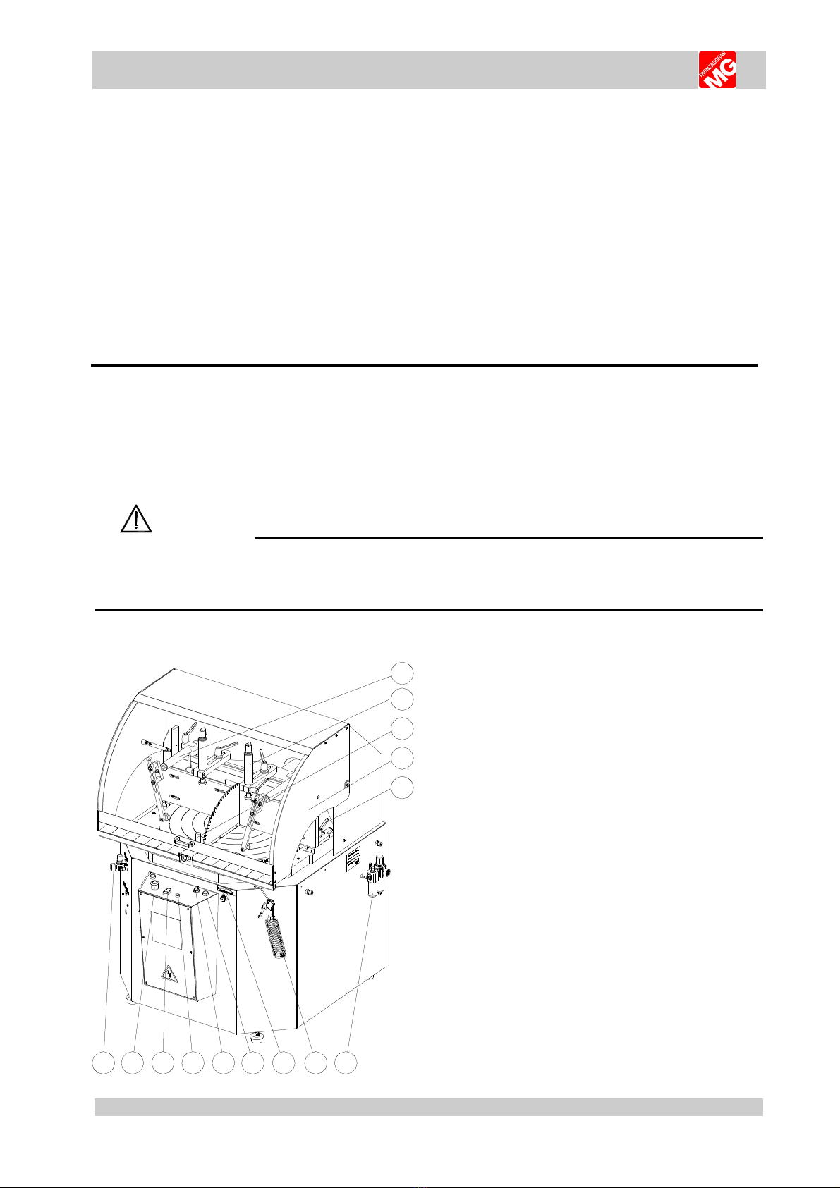
5.2. Function of the operating mechanisms.
1. Horizontal clamps.
2. Vertical clamps.
3. Lever I turn disc.
4. Protective shield.
5. M10x40 Lever.
6. Filter + Regulator + lubricator + manometer.
7. Clearing gun with hose.
8. Advanced regulator 3/8”.
9. Raise blade - green button.
10. 2-position selector.
11. Green indicator 380V.
12. Saw blade on-off.
13. Emergency.
14. Pressure regulator horizontal clamps.
1
2
3
4
5
6
7
89
10
11
1213
14

10
TL
-
6
00
-
A
DANGER
ALWAYS WORK WITH THE PROTECTIVE SHIELD LOWERED.
DO NOT DISCONNECT ANY SAFETY DEVICES.
5.3. Instructions for the adjustment of the digital degrees. (OPTIONAL)
For placed to the zero of the book-keeper of degrees, pulsate of simultaneous form (F+Set).
To change the way of reading of incremental to absolute, to touch (Inc/Abs).
Change of the book-keeper parameters, contact to the manufacturer of the machine.
ATTENTION
Clean the book-keeper with the pistol of cleanliness, not to try to clean it with other utensils
since the frame of plastic might be spoilt or grated, impeding the reading
5.3. General rules and safety checks.
•Before using the machine, check the efficiency and perfect operation of all safety devices, and
check that the moving parts of the machine are not blocked, that there are no damaged parts and
that all machine components are positioned and work correctly.
•It is entirely prohibited to manipulate the safety devices.
•It is entirely prohibited to work without the protective shield in position.
•It is mandatory to use gloves and protective eyewear.
•It is mandatory to use regulation work clothing (it must be worn fastened).
•Before starting work, the operator must ensure that all tools and wrenches used for maintenance or
adjustment have been removed.
•In the event of a fire, use powder extinguishers and disconnect the machine from the electric
system.

11
TL
-
6
00
-
A
6. RECOMMENDATIONS AND MAINTENANCE. >>>
6.1. Type and frequency of inspections.
The operator’s knowledge of the machine is one of the best ways of daily control of any
possible problem. If any failure is detected, work must be stopped and qualified personnel must be
informed immediately.
NOTE
Always clean the machine and the work area at the end of the workday.
LUBRICATION POINTS TYPE OF GREASE/OIL FREQUENCY
Turret travel rail SAE 30 LUBRICATING OIL WEEKLY
Rocker bearings (Fig. 7.4) ROLLER BEARINGS ANNUALLY
CHECK POINTS FREQUENCY
Machine cleaning WEEKLY
Condition of the transmission belt ANNUALLY
6.2. Qualified personnel for maintenance and repair work.
•All repairs shall be made exclusively by qualified personnel, thereby always using original
replacement parts. If not, the machine may be damaged or the user may be injured.
6.3. Manufacturer recommendations.
⇒In the event that the machine is broken down or the saw blades must be replaced, place a padlock
on the protection switch and place the keys under the care of qualified personnel.
⇒Before working on any electrical devices, disconnect the plug from the power supply.
⇒If extension cords are used, ensure that the cable has the appropriate cross-section for the power
of the machine.
⇒Whenever any part has to be replaced, use an original replacement part and endeavour to use the
oil recommended by the manufacturer.
NOTE
In case of any doubt or problem, do not hesitate to consult the manufacturer.
ATTENTION
The manufacturer hereby guaranties the supply of each one of the parts or components for at
least 3 years as from the manufacturing date of the machine.
12
TL
-
6
00
-
A
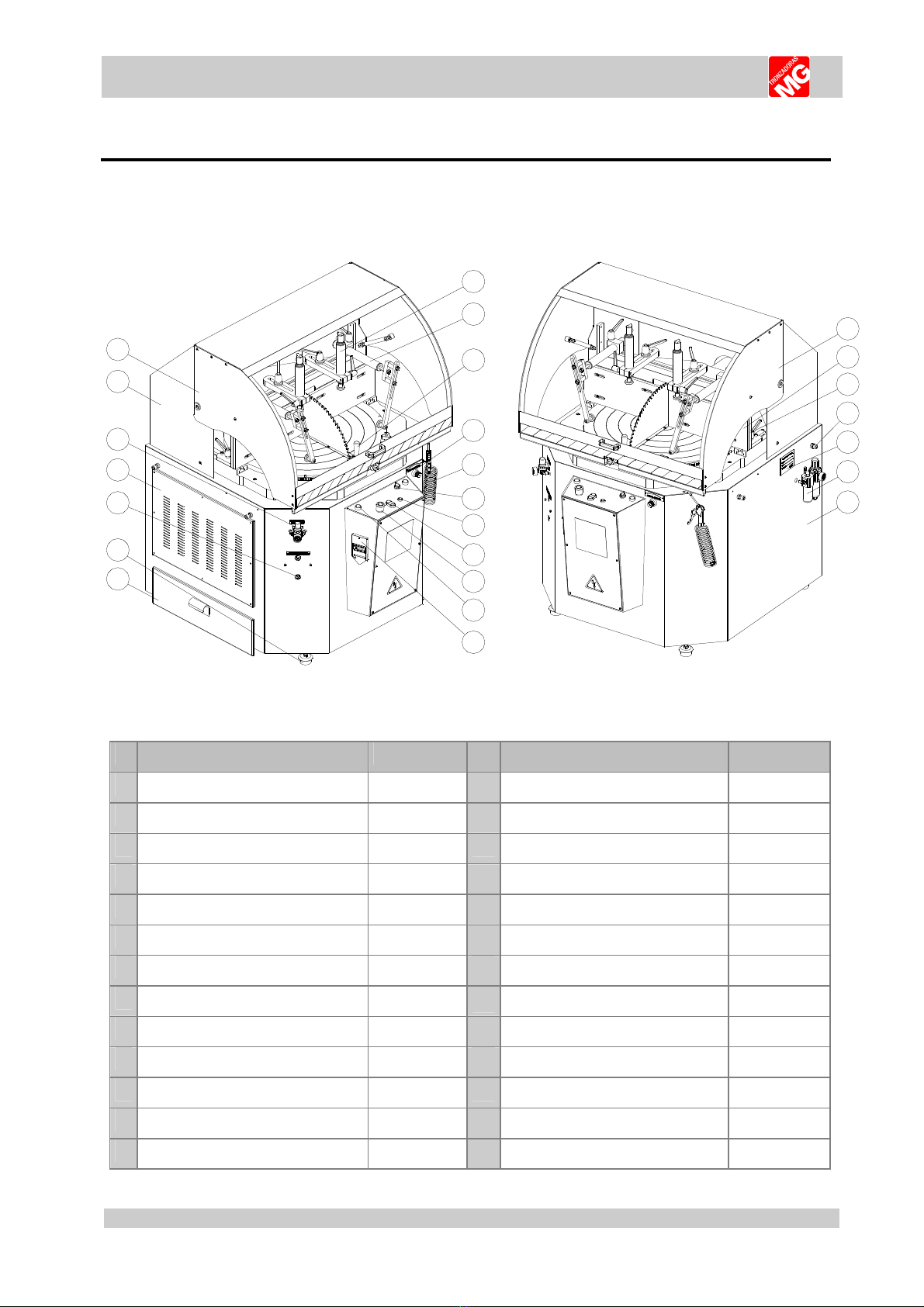
7. DRAWINGS AND SCHEMATICS. >>>
7.1. General schematic.
1
2
3
4
5
6
7
8
9
10
11
18
17
16
15
14
13
12
19
20
21
22
23
24
25
Nº DESCRIPTION CODE Nº DESCRIPTION CODE
1 Ø45 PNEUMATIC HOLD-DOWN CLAMP 2050000202 14 OLEONEUMATIC CONVERTER 2040000092
2 HORIZONTAL CLAMPS ØEXT 40 N00PTI4050 15 LEFT DOOR
3 ANGLE LOC 2040000482 16 PRESSURE REGULATOR N000000030
4 ADVANCE REGULATOR 3/8” N000000018 11 PROTECTIVE SHIELD SUPPORT
5 BLOW AIR DUSTER 18 PROTECTIVE SHIELD
6 2- POSITION SELECTOR 19
SHIELD END-OF-TRAVEL STOP
E00000BD25
7 GREEN INDICATOR E0000000030 20 TURRET
8 SAW BLADE ON-OFF 21 M10x40 LEVER B000091040
9 EMERGENCY 22 M14x40 SCREW + M14 NUT x (2)
10 GEEN VERTICAL ALINGMENT BUTTON 23 CE IDENTIFICATION
11 GENERAL SWITCH 24 FILTER+REG.+LUBRIC.+MANOM. N000000A17
12 SIDE DRAWER. CUTTINGS 25 SHEET METAL BASE
13 FEET LEVELERS
13
TL
-
6
00
-
A
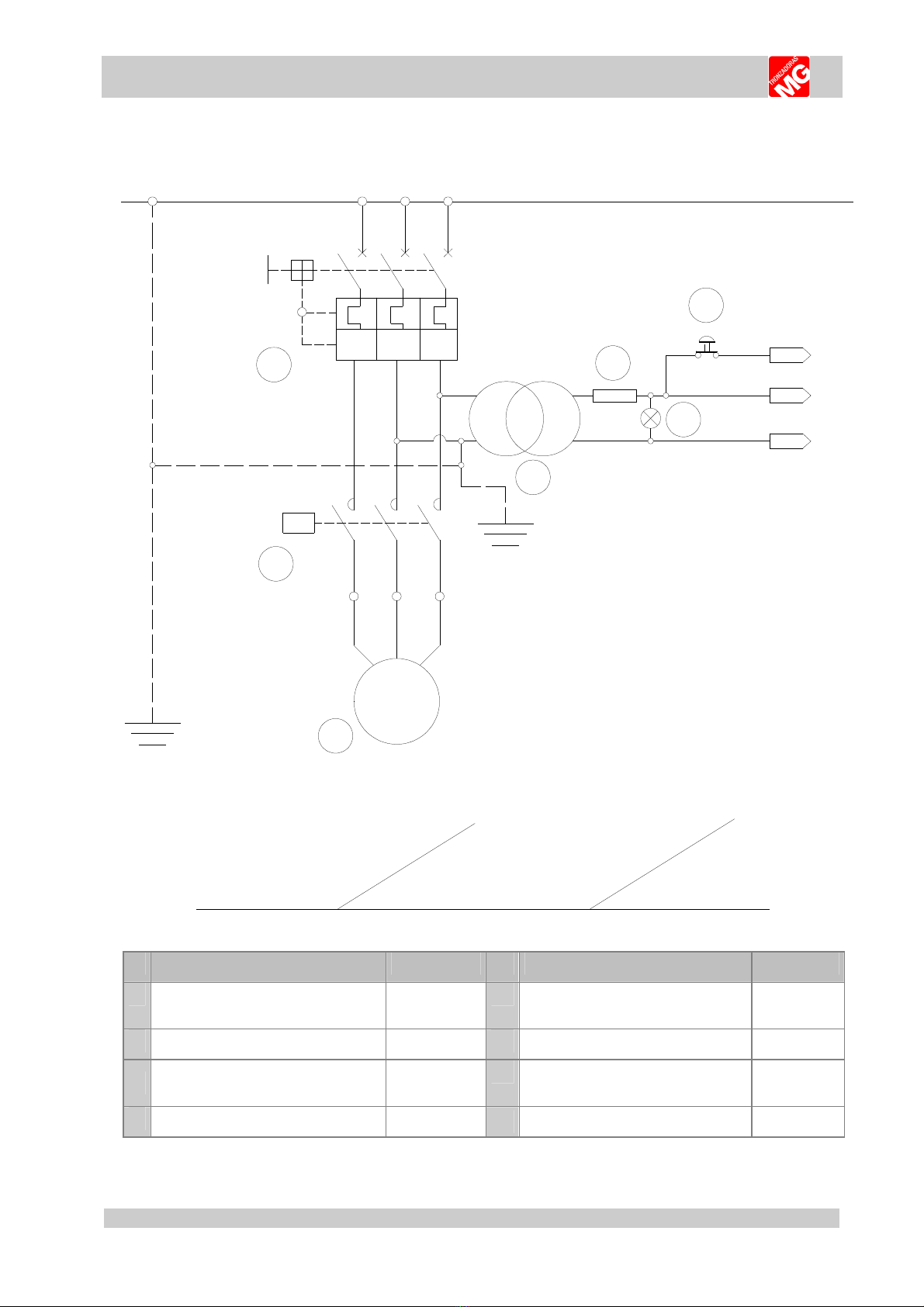
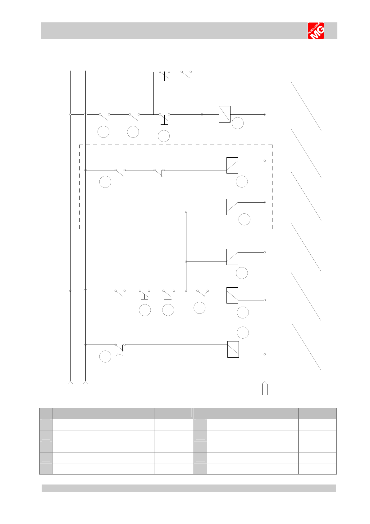
7.2. Power circuit.
L1 L2 L3
1L1 1L2 1L3
I> I> I>
M1
U1 V1 W1
QM1
KM1
~3Kw III 400V
3Kw III 220V
50/60 Hz
4,7A / 8,14A
380V --> 8A
220V --> 13A
50VA
2A
RS T
P
(380-220)V --> 24V
24
0
124
1
2
3
4
5
6
7
BRAKEMOTOR3Kw
Contactor
MAINSWITCH
FUSE
TRANSFORMER
50VA
M RG NCIA
L D T NSIÓN
Nº DESCRIPTION CODE Nº DESCRIPTION CODE
1 MAIN SWITCH 10A
MAIN SWITCH 16A
E000000004
E000000005
5 FUSE 2A E000000024
2 CONTACTOR T C9 24V 50/60HZ E000000034 6 EMERGENCY (NC) E000000G44
3 3 W MOTOR III 400V C/FRENO
3 W MOTOR III 220V C/FRENO
21600000M3
21600220M3
7 GREEN INDICATOR Ø17 VERDE 24V E000000030
4 TRANSFORMER 50VA - 24V E000000014
14
TL
-
6
00
-
A
124
24
124
124
24
1
Q1
Q3
Q2
11
124
3
4
5
12 13
KM1
14
6
7
126
125
8
13
12
12
9
10
10
11
14 15
OPENCLAMPS
BLADEROTATION
BLADEUP
CLAMPS
BLAD UP
BLAD UP
SHI LD
LAT RAL
DOOR
R AR
DOOR
START - STOP
BLAD
KM1
MAX-MINPRESURE
5B
0
124
24
0
R1
15
17
5
16
LOW R BLAD
R1
Q4
16
13
9
8
OPENSHIELD
RELAYOFRAISE
13
AUTOMATIC
SWITCHING POWER CIRCUIT
SHIELD
Nº DESCRIPTION CODE Nº DESCRIPTION CODE
8 2-POSITION SELECTOR E000000G71 13 5/2 WAYS MONO. ELECTROVALVE N000000A34
9 SHIELD END-OF-TRAVEL STOP E00000BD25 14 HIGH + LOW PRESSURE NEUMATIC N000000069
10 END-OF- TRAVEL M-12 E000000015 15 T C9 CONTACTOR 24V 50/60 Hz E000000034
11 SAW BLADE , ON-OFF E000000G75 16 MAGNETIC SENSOR MAGI 6,2 ECN T50RQD
12 GREEN PUSH-BUTTON NO E000000G50 17 RELAY BORNA 6MM + BASE 24VAC/DC E000000095
15
TL
-
6
00
-
A
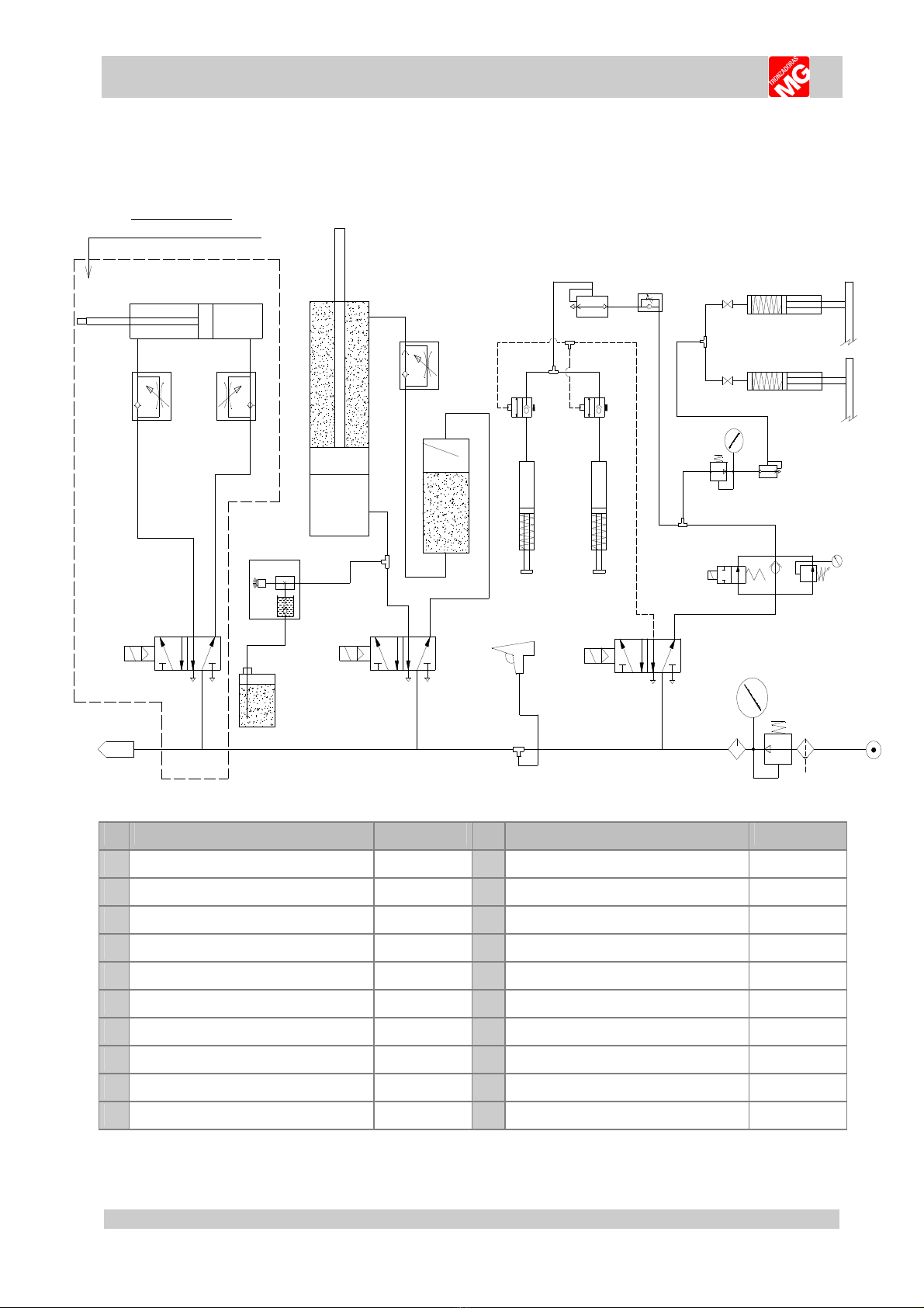
7.3. Pneumatic schematic.
51
42
51
42
EQ1
EQ2
LIN A
EQ3
00
01
02
03
05 04
06
06
08
09
1010
11 11
12
13
14
15
16
18
17
07
07
51
42
EQ4
13
TL-600-PLUS
AUTOMATIC SHI LD
Nº DESCRIPTION CODE Nº DESCRIPTION CODE
00 LINE -------------------- 10 UNI DIRECTIONAL VALVE 2/2 1/8” N000000015
01 F+R+L 1/4 “ N000000A17 11 VERTICAL CLAMPS Ø45 2040000212
02 5/2 WAYS MONO. ELECTROVALVE N000000A34 12 BLOW AIR DUSTER N000000010
03 HIGH+LOW PRESSURE NEUMATIC N000000069 13 5/2 WAYS MONO. ELECTROVALVE N000000A34
04 QUIC EXHAUST VALVE 1/8” N000000038 14
OLEONEUMATIC CONVERTER
2040000092
05 PRESSURE REGULATOR ¼” N000000030 15 OIL REGULATOR 3/8” N000000018
06 CLAMPING CYLINDER Ø40x320 N02PTI4050 16 CYLINDER ISO 50x200 N000000025
07 MINI BALL VALVE 1/8” M-H 2 20000281 17
VENTURI
N000000036
08 FLOW REGULATION 1/8" Ø6 CIL. N0CCRC1806 18
CUTTING OIL RESERVOIR
2060000383
09 QUIC EXHAUST VALVE 1/8” N000000038 19
16
TL
-
6
00
-
A
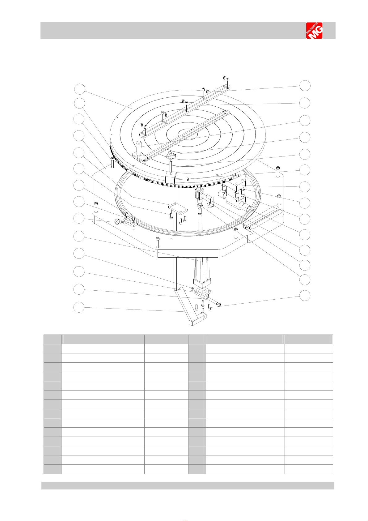
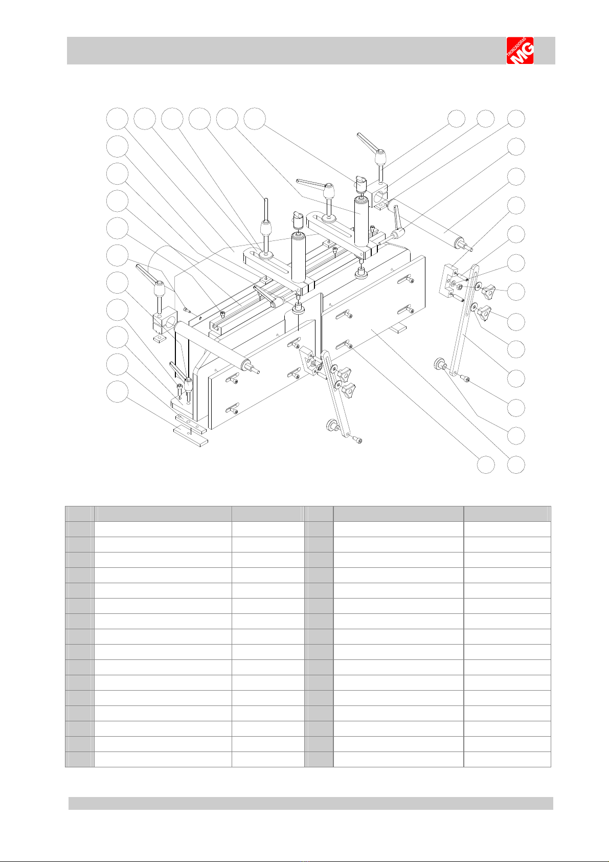
7.4. Exploded view cast iron table and disc assembly.
1
2
3
4
5
6
7
8
9
10
11
12
13
14
15
16
17
18
19
20
21
22
23
24
25
26
27
28
Nº DESCRIPTION CODE Nº DESCRIPTION CODE
1 DIN 7991 M6x16 SCREW TD79910616 15 POST
2 BLADE GROOVE 16 ISO 50 CYL. YO E N000000059
3 DEGREES TURN LEVER
2352000171
17 ISO 50 CYL. YO E N000000059
4 HANDLE TRISTAR M10
B0000000H2
18 STOP COLLAR CIL. ISO 50 N000000059
5 DIN 913 M10x70 SCREW TD91310070 19 ISO 50x200 CYLINDER N000000026
6 BRA E OF DEGREES 20 M8 NOB B000000011
7 ROC ER SUPPORT 21 ANGLE LOC 2040000482
8 DIN 128 Ø12 WASHER TD12800012 22 DIN 7991 M8x20 SCREW TD79910820
9 DIN 912 M12x50 SCREWS TD91212050 23 DIN 912 M8x25 SCREW TD91208025
10 AUTOLUBRICATED TIP 30-35-35 24 LEVER SUPPORT
11 ISO 50 CYL. FEMALE PIN JOINT N000000057 25 CAST IRON TABLE
216000F012
12 ISO 50 CYL. FEMALE PIN JOINT N000000057 26 DIN 912 M10x70 SCREW
TD91210070
13 DIN 934 M16 NUT TD93400016 27 INDICATOR OF DEGREES
2160000CG2
14 DIN 912 M8x25 SCREW TD91208025 28 CAST IRON DISC
2160000022
17
TL
-
6
00
-
A
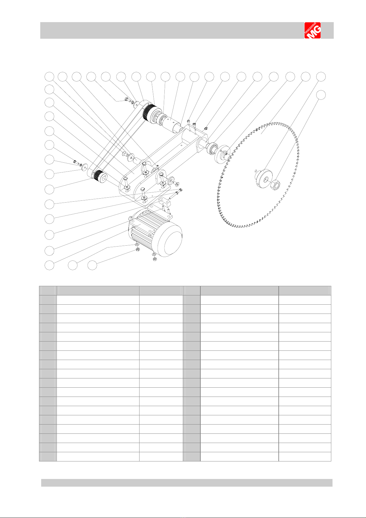
7.5. Exploded view rocker assembly.
1
23
45
6
7
89
10
11
1213
1415
16
17
181920
21
22
23
24
25
26
27
28
29
30
31
32
33 34 35
Nº
DESCRIPTION CODE Nº
DESCRIPTION CODE
1
DIN 934 M30
NUT
TD93400030
19
CONNECTING ROD PIN
2
BLADE WASHER
2040000042
20
Ø45x7 AVELL. M12
WASHER
216000A452
3
WIDIA BLADE
Ø600xØ50x5
205DW60032
21
DIN 7991 M12x25
SCREW
TD79911225
4
DIN 912 M8x12
SCREW
TD91208012
22
CAST IRON ROC ER
TL
-
600
2160000032
5
4206
BEARING
2040000172
23
DIN 933 M10x50
SCREW
TD93310050
6
Ø30 SHAFT
2040000102
24
Ø10 INT. PISAD.
WASHER
204000A401
7
LUBRICATOR
1/8”
2070
000012
25
DIN 933 M8x25
SCREW
TD93308025
8
DIN 912 M6x10
SCREW
TD91206010
26
DIN 128 Ø8
WASHER
TD12800008
9
DIN912 M8x16
SCREW
TD91208016
27
Ø40x
Ø8x
6mm
WASHER
204000A402
10
Ø36
SEPARATOR
2040025582
28
MOTOR PULLEY
11
Ø60
SEPARATOR
2040060582
29
D
IN933 M8x80
SCREW
TD93308080
12
4206
BEARING
2040000172
30
DIN934 M8
NUT
TD93400008
13
ROC ER SHAFT PULLEY TL
-
600
31
BELT TENSION ADJUSTER
14
960
J12
POLY
-
V BELT
32
DIN 912 M8x30
SCREW
TD91208030
15
Ø40xØ10x6mm
WASHER
204000A401
33
4HP III P
HASE MO
TOR
21600000M3
16
DIN 128 Ø10
WASHER
TD128000010
34
DIN 125 Ø10
WASHER
TD125000010
17
DIN 933 M10x25
SCREW
TD93310025
35
DIN 934 M10
NUT
TD93400010
18
DIN 913 M8x16
SCREW
TD91308016
18
TL
-
6
00
-
A
7.6. Exploded view turret assembly.
1
2
3
4
5
6
7
8
9
12 13 14 15 16 17 18 19
20
21
22
23
24
25
26
27
28
29
30
10
11
3132
Nº
DESCRIPTION
CODE
Nº
DESCRIPTION
CODE
1
LOC GUIDE PLATE
17
M12x70
LEVER
B0000P1270
2
TURRET COTTER
18
ALUMINIUM ROD. HOR. CLAMP
204000A502
3
IRON TURRET
19
FLAT NUT M12
4
DIN 912 M10x30
SCREW
TD91210030
20
M10x60
LEVER
B0000P1060
5
M
10x40
LEVER
B000091040
21
HORIZONTAL CLAMP
Ø40x160
N00PTI4050
6
DIN 912 M6x16
SCREW
TD91206016
22
SUPPORT OF DRAWER
.
7
DIN 912 M8x12
SCREW
TD91208012
23
D913 M10x40
TD93310040
8
CLAMPS ALUMINIUM GUIDE
24
D125 Ø10
WASHER
TD12500010
9
NYLON CLEAT BLA
C
M10
2350000131
25
D934 M10
NUT
TD93400010
10
FLAT NUT M12
26
HANDLE
TRISTAR HEMBRA M10
B0000000H2
11
TURRET PROTECTOR
27
Ø20
-
Ø10 WASHER
2130000011
12
Ø45 ALUMINIUM ROD
28
HORIZONTAL CLAMPS ARM
13
Ø45
-
Ø12 WASHER
204000A401
29
DIN 912 M10x20
SCR
EW
TD91210020
14
M12x70
LEVER
B0000P1270
30
NYLON CLEAT BLAC
M10
2350000131
15
PNEUMATIC CLAMPS
Ø45x115
2040000212
31
ALUMINIUM PLATES
TL
-
600
16
SECURITY VALVE
N000000015
32
DIN 912 M8x16
SCREW
TD91208016
19
TL
-
6
00
-
A
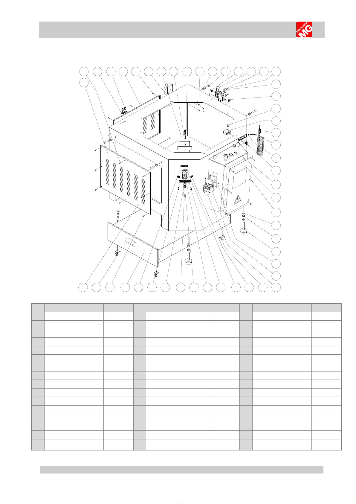
7.7. Exploded view sheet metal base.
1
234 5 678910 11 12 13 14 15 16 17
18
19
20
21
22
23
24
25
26
27
28
29
30
31
32
33
34353637
38
3940
41
4243
4445
46
47
48
Nº
DESIGNATION
CODE
Nº
DESIGNATION
CODE
Nº
DESIGNATION
CODE
1
LEFT DOOR
17
D912 M5x16
SCREW
TD91205016
33
COVER BOX SWITCH
2
ISO7380 M6x20
SCREW
TI73800620
18
D128 Ø5
WASHER
TD12800005
34
CLOSING PADLOC S
3
D934 M14 NUT
TD93400014
19
MALE STUD ELBOW 1/4 - Ø8
N000CC1408
35
WHEEL FIXES
PP Ø30
216000030F
4
CONNECT
Ø6
-
Ø6
2050000262
20
D934 M14 NUT
TD93400014
36
MALE STUD ELBOW 1/4 - Ø6
N000CC1406
5
BAC DOOR
21
OIL
REGUL
ATOR
.
3/8”
N000000018
37
SQUARE REGULATOR
N00000
0E30
6
ISO7380 M6x20
SCREW
TI73800620
22
CLEANING GUN WITH HOSE
N000000021
38
D912 M5x10
SCREW
TD91205010
7
THREE
-
PHASE BASE
E000000022
23
SUPPORT
M6
T0000000H6
39
PRESURE REGULATOR
1/4”
N000000030
8
OLEONEUMATIC CONV.
24
D934 M6
SCREW
TD93400006
40
Ø40
MANOMETER
N000000020
9
REDUCTION
1/2M
–
1/4H
N00RHM1412
25
OIL REGULATOR
NOB
B000003823
41
METAL STOPPER
GAS 3/8”
N0000TA012
10
MALE STUD ELBOW 1/4 - Ø8
N000CC1408
26
CONTROL PANEL
42
METAL STOPPER GAS 3/8
”
N0000TA012
11
D912 M4x10
SCREW
TD91
204010
27
COVER CONTROL PANEL
43
D912 M6x16
SCREW
TD91206016
12
D934 M14 NUT
TD93400014
28
ISO 7380 M5x10 SCREW
TI73800510
44
MALE STUD ELBOW 1/4 - Ø6
N000CC1406
13
D912 M14x40
SCREW
TD91214040
29
D125 Ø12
WASHER
TD12500012
45
BOOTH OF SHAVING
14
ADA
PTOR
¼
”
Ø8
N0000E0914
30
D934 M12
NUT
TD93400012
46
ISO7380 M6x20
SCREW
TI73800620
15
F+R+L 1/4”
N000000017
31
FOOT LEVELER M12
2FR450B003
47
WHEEL
Ø30
216000030P
16 Ø40 MANOMETER N000000020 32 BOX SWITCH E0000000M6 48 LEFT DOOR
20
TL
-
6
00
-
A
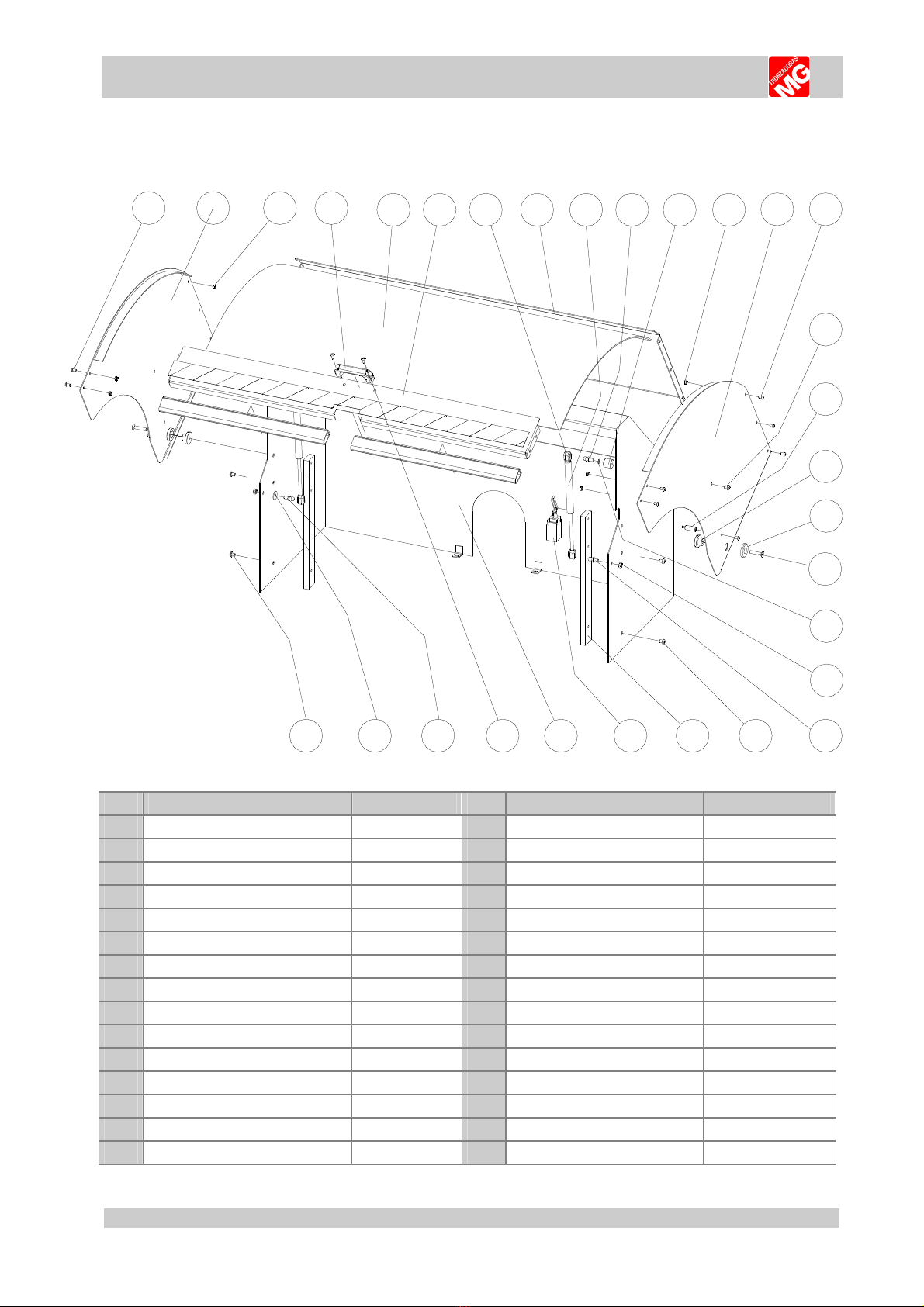
7.8. Exploded view protective shield.
12 3 456789
10 11 12 13 14
15
16
17
18
19
21
2223242528 262930
20
27
Nº
DESCRIPTION
CODE
Nº
DESCRIPTION
CODE
1
ISO
-
7380 M6x10
SCREW
TI73800610
16
FINAL GUIDE OF
END
-
OF
-
TRAVEL
-----------------
2
LEFT PROTECTIVE SHIELD
-----------------
17
CONNECTING ROD PIN P. SHIELD
-----------------
3
DIN
-
934 M6
NUT
TD93400006
18
Ø40x6 AVELL. M8
WASHER
204000A401
4
M8
HANDLE
B000000015
19
DIN 7991 M8x40
SCREW
TD79910840
5
1090x670x3
METHECRYLITE
2160000142
20
DIN 125 Ø8
WASHER
TD12500008
6
FRONT CLOSING
-----------------
2
1
DIN
-
985 M8
NUT
TD98500008
7
SWIBEL JOINT
204000R452
22
BALL SCREW
Ø10 M8
20400TB452
8
ABOVE CLOSING
----------------
23
ISO
-
7380 M6x10
SCREW
TI73800610
9
SHOC ABSO.
R300
-
L125
-
250N
2160000300
24
SHIELD POST
-------------------
10
BALL SCREW
Ø10 M8
20400TB452
25
END OF
TRAVEL
E00000BD25
11
SEPARATOR M8x20 Ø25mm
---------------
26
PROTECTIVE SHIELD SUPPORT
-------------------
12
DIN
-
934 M6
NUT
TD93400006
27
DIN 912 M6x16 + DIN 934 M6
TD91206016
13
RIGTH PROTECTIVE SHIELD
-------
---------
28
BALL SCREW
Ø10 M8
20400TB452
14
ISO
-
7380 M6x10
SCREW
TI73800610
29
DIN125 Ø8
WASHER
TD12500008
15
ISO
-
7380 M8x10
SCREW
TI73800810
30
ISO
-
7380 M6x10
SCREW
TI73800610
Table of contents
Popular Saw manuals by other brands


Central Machinery
Central Machinery 97099 Set up and operating instructions

Toolex
Toolex 532215 instruction manual

Scheppach
Scheppach Special Edition HS 720 Translation from original manual

Metabo
Metabo KGS 303 PLUS Original operating instructions

Sears
Sears 113.244200 owner's manual

Stanley
Stanley STEL701 instructions

CUTS DIAMANT
CUTS DIAMANT MC 301 User and maintenance manual

Craftsman
Craftsman 172.10865 12 Amp Operator's manual

Charnwood
Charnwood SS16F owner's manual

Stanley
Stanley Fatmax SFMCS701 Original instructions

Craftsman
Craftsman 113.196421 owner's manual

King Industrial
King Industrial KC-1433FXR instruction manual