Tropicair KOWHAI Mk3 User manual
Revised February 2017
HEATING Ltd
Over
40
years experience in heating manufacture
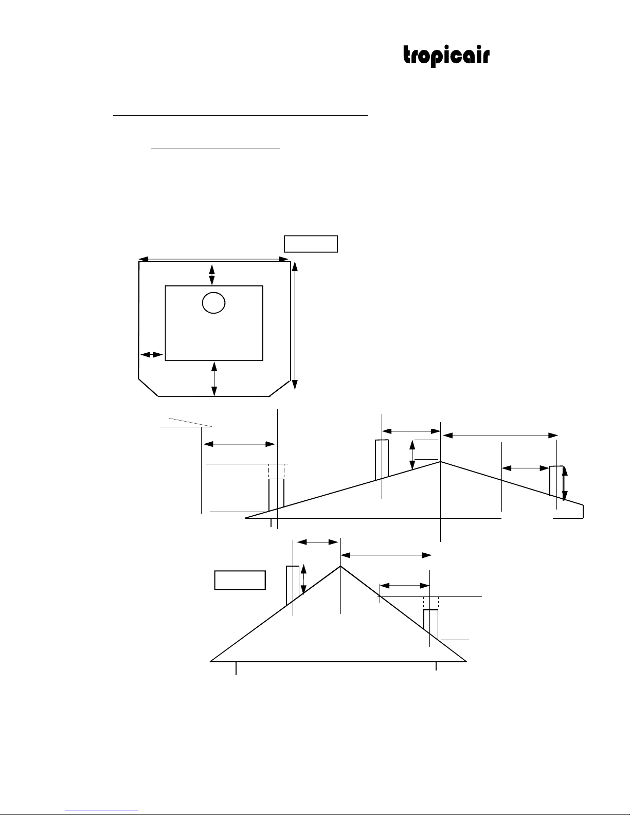
a. A minimum of 4m of the flue height is recommended for the correct flue draft. [i.e.4600mm minimum overall height from the (floor
protector) hearth]
b. In case of a pitched roof the chimney shall extend not less than 600mm above the highest point of the roof.
c. All parts of the chimney exposed to the outside air shall be suitably insulated in accordance with Tropicair Heating Ltd’s
recommendation.
d. Where possible install our Tropicair flue kit with the unit. (or a flue kit which complies with NZS7421:1990)
e. When deciding the position of the unit try to avoid unnecessary complications in the ceiling. i.e. rafters, beams, valleys and ridges.
600m
in.
3000 or less
600m
in.
100mm
I. GENERAL INFORMATION.
a. The installation must comply with local council regulations.
b. It is recommended that the woodburner be installed by a registered plumber or a NZ Home Heating Association qualified
heating installer, who should work in accordance with good trade practice.
c. The unit should be installed in such a manner that parts are accessible for inspection and maintenance
d. A suitable fire extinguisher should be installed on the premises.
1000mm
900mm
II. ASH HEARTH
III. FLUE HEIGHT.
1000 min. if clear
within
3000 of flue top
fig. 2
1
.
300mm
50mm
fig. 1
3000 or less
more than 3000
more than 3000
increase from 1000
min. until clear
within
3000 of flue top
3000
3000
3000
nearby
structure
increase as nec.
until nothing
within 3000 of
flue top
Installation Instructions for KOWHAI Mk3 (in accordance with AS/NZS2918:2001)
AUTHORISATION NUMBER: 090722
1. An ash hearth shall must be 300mm in front of the firebox and
100mm at each side. Measured as per AS/NZS2918:2001
2. A woodburner must have a minimum of 1 metre clearance in
front of any building structure or any other substantial
immovable object.
3. Minimum Corner hearth size 1120mm x 1120mm
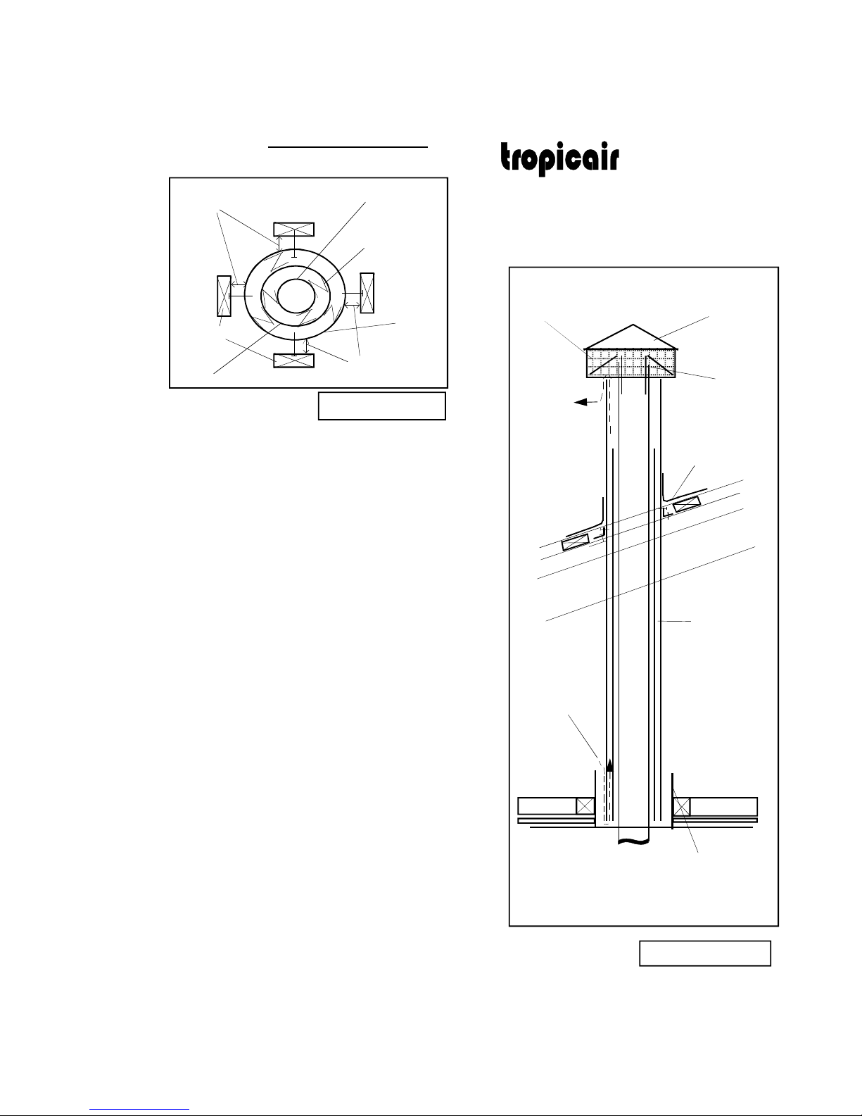
Installing the
TROPICAIR
FLUE
kit
150mm flue
200mm
liner
Timber
250mm
liner
centralising z
brackets
fig. 3 Plan View
fig. 4 cross-section
cooling
air
OPTIONAL
secondary
300mm
Shield
AQUASEAL
or LEAD roof
flashing
cowl
150mm
flue
To
outside
250mm
liner
optional
bird-proof
netting
2.
25mm
air gap
25mm
air gap
HEATING Ltd
Over 35 years experience in heating manufacture
1. Position the heater on floor, drop a plumb line
from the ceiling to the centre of the unit collar
to mark the position where the flue will pass
through the ceiling.
2. Cut a 300mm diameter hole in the ceiling and
roof above, and frame timber around both
300mm holes, to support heat shield liners.
3. Fix 300 mm diameter x 240mm long shield
(provided in flue kit) to timber framing. Allow
shield to penetrate inside the room for 5mm.
4. Position the 250mm liner inside the fixed shield
and fasten to timber top and bottom. (with
bracket supplied and 25mm clear of timber)
5. Fasten the flue together with stainless steel
pop-rivets (swagged end of the flue at bottom)
and drop through liner into the heater spigot.
At this stage the ceiling plate should be fitted
through flue and can be lifted up and screwed on.
6. Flash the roof to the galvanised liner with appropriate
Flashing (Varies from council to council)
7. Where the chimney extends more than 1.2m-2m above
roof penetration (council depending), it will require restraining
aluminium stays.
8. After installation of the flue, the installer is to
ensure the unit is level and fixed securely to the floor
using seismic restraints (8mm dynabolts or flush head
sleeve anchors) fitted at the rear.

F
100mm
C
425mm
I
425
I
100
C
D
175mm
B
50mm
fig. 7
corner clearances
fig. 5
side clearances
A
455mm
V. CLEARANCES for Kowhai Mk III
fig. 6
back clearances
D
E
G
J
3
.
H
HEATING Ltd
Over 35 years experience in heating manufacture
SPECIFICATIONS for KOWHAI Mk III
FIREBOX DIMENTIONS / MATERIAL
450mm x 350mm / 6mm plate steel
SECONDARY COMBUSTION AIR standard equipment
MAXIMUM LOG LENGTH 460mm
HEAT OUTPUT MAXIMUM 18kw
HEAT OUTPUT LOW AVERAGE 9.5kw
EFFICIENCY MAXIMUM 76%
EFICIENCY OVERALL AVERAGE 71.8%
DOOR OPENING SIZE 390mm x 270mm
GLASS SIZE / MATERIAL 325mm x 195mm/5mm Robax
ceramic
CONTROLS single slide top front right
FLUE DIAMETER / MATERIALS 150mm / 24g T304 stainless steel
HEIGHT OF STANDARD FLUE KIT 3 x 1200mm flues
CLEAN AIR TESTING AS/NZS 4012:1999 passed 71.8%
AS/NZS 4013:1999 passed 0.89g/kg
APPLIANCE WEIGHT 88kg
COOKING FACILITY standard
COLOUR CHOICE black,brown,grey,green,navy
WARRANTY 5 years
MINIMUM ASH HEARTH SIZE 900mm wide x 1000mm deep
MINIMUM CORNER ASH HEARTH
1100mm X 1100mm
HEATING Ltd
Over 35 years experience in heating manufacture
A SIDE OF
WOODBURNER TO WALL
4
45
mm (shielded flue)
B BACK OF WOODBURNER TO WALL 50mm (shielded flue)
C REAR CORNER OF WOODBURNER TO WALL 100mm (shielded flue)
D CENTRE FLUE TO BACK OF WOODBURNER 175mm
E FIRE OVERALL HEIGHT 710mm
F FIRE OVERALL DEPTH 590mm
G OVERALL WIDTH 560mm
H CENTRE FLUE TO WALL 225mm See Appendix A (1)
I CENTRE FLUE TO WALL - CORNER SITUATION 425mm See Appendix A (1)
J DIAMETER OF FLUE SPIGOT 150mm
CLEARANCE FROM COMBUSTIBLES & DIMENSIONS (figs. 5,6 &7)

~ Special Conditions
(1) Flue Center Measurements
Flue center measurements as tested for this appliance under AS/NZS2918:2001 Appendix F in the standard orientation
(back of appliance parallel to wall) has a tested center measurement of 225mm. In a corner environment the flue center at
the heater flue outlet is 425mm. This measurement should be treated as indicative to centering the logfire as actual safe
tested clearance is permitted down to 225mm at the heater flue outlet regardless of orientation Eg: a corner install could
be offset at or above the appliance to arrive at a 225mm flue center with standard 1200mm flue shield altered to give
cover down to the appliance.
(2) Offsets
Offsetting as long as it is after the first 1200mm flue length, which has been fitted with specified minimum 1200mm single
skin shield (Multi skinned shields acceptable) As per AS/NZS2918:2001 4.5.2 is found to have “Cooled Considerably”, and as
such we are happy for offsets up to 150mm to center from combustibles to be used without shielding. Should the required
offset shift the flue center closer than 150mm toward combustibles, then shielding to the wall must be used. This has been
determined through both historic experience and parameters within the standard.
It is important to note that while combustible temperatures may not be significant enough to cause rise above ambient of
65 Degrees C as set out in the standard’s Appendix F, Prolonged exposure to heat may cause wall linings and furnishings to
tarnish, deform or discolour over time and this should be considered when offsetting.
(3) Alcoves
Though this unit has not been tested in a combustible lined alcove specifically, The unit has been tested to Appendix B of
AS/NZS2918:2001 for side clearance to a left or right adjacent wall. The alcove being simply an adjacent wall to the left
and right should be factored as follows.
An alcove of 1460mm is the smallest permitted alcove at standard clearances for this model fire (445mm Left clearance +
560mm fire width + 445mm right clearance + 10mm Variable).
Wall shields shielding side or rear walls can reduce these clearances as appropriate under the standard’s Section 3.2.3 table
3.1 and 3.2
Horizontal surface at the top of an alcove must be a minimum of 2210mm above floor protector (1500mm + Heater top face
710mm). Clearances can be reduced through shielding as per Section 3.2.3 Table 3.1 and 3.2
If building the alcove we would recommend the top of the alcove be built with a slope between 5-15 degrees to assist
convection. Alcoves with shielded walls may funnel more heat up to the ceiling and a sloped ceiling or a Larger 600mm x
600mm should be used where practical. Using Eterpan or a similar non combustible lining would reduce the need for an
oversized ceiling plate.
(4) Front clearance
Tropicair fires can have the 300mm front clearance measured from the bottom lip of the firebox opening with the door in
an open position as per AS/NZS2918:2001 Section 3, 3.3.2
(5) Triple skinned Offsets
TS Offsets are an acceptable alteration as long as all clearance factors (25mm to combustibles) are adhered to at all times,
the flue remains concentric inside the offset and all skins (150 – 200 – 250) are used in there entirety.
(6) Installations
While it is not required by law that this appliance is installed by an NZHHA accredited SFAIT installer failure to
install this appliance and flue system to the specified standard or applicable acceptable standard AS/NZS2918:2001
may affect performance and warranty of this product in the future.
This instruction can be used for the Kowhai 2000 including Wetback model
Table of contents


