TROVIS 3730-1 User manual

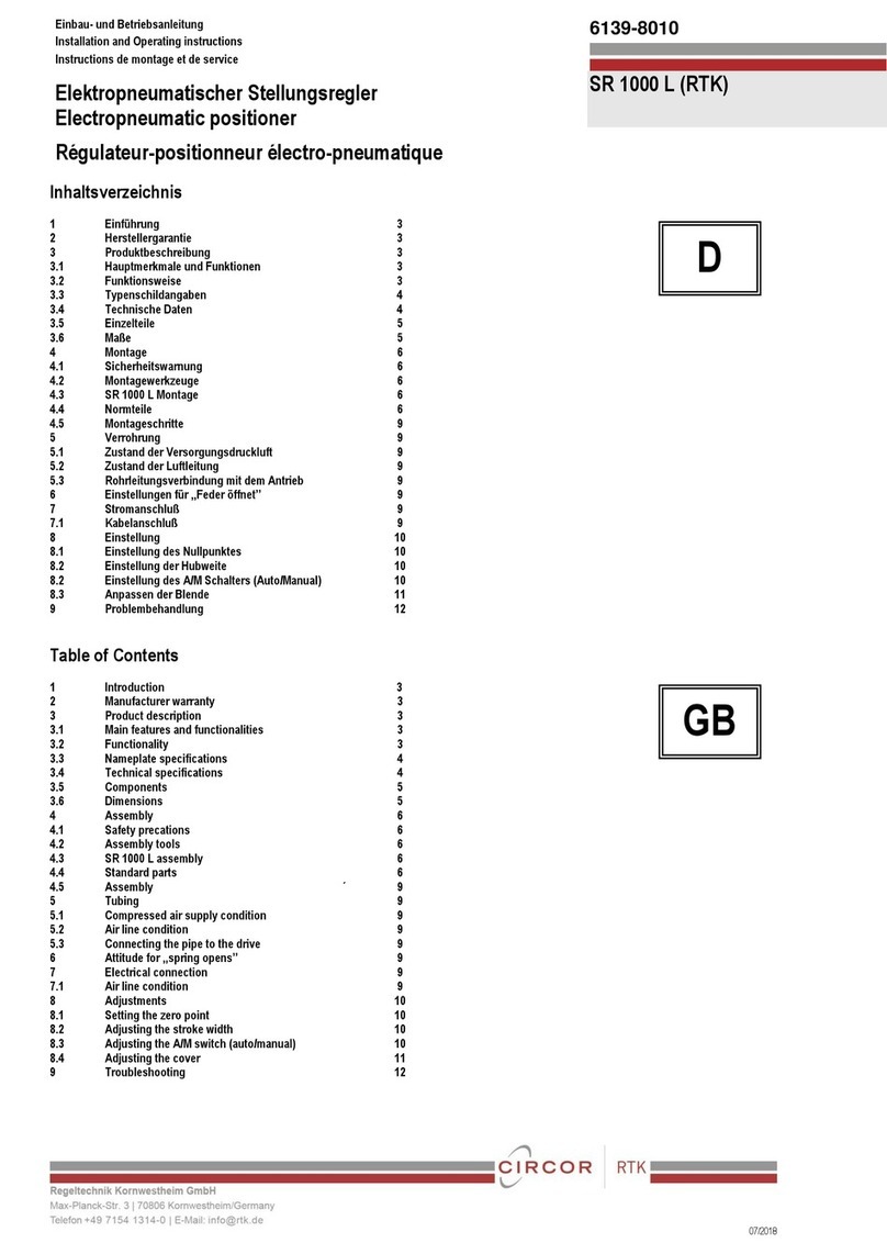
TROVIS3730-1 Electropneumatic Positioner
This quick guide does not replace the mounting and operating ins-
tructions supplied with the positioner. Observe the safety instructions
as well as the warning and caution notes specied in the mounting
and operating instructions.
1 Mounting
Direct attachment to SAMSON Type3277 Actuator
Travel [mm] Actuator [cm²] Lever Pin position
15 120, 175, 240, 350 M35
30 355, 700, 750 M50
ÎTo mount the positioner, lift the lever so that the follower pin rests
on the follower clamp of the actuator stem. Make sure the lever
can move freely.
NAMUR attachment
Travel [mm] Actuator [cm²] Travel Pin position
7.5 and 15 120, 175, 240, 350, 700, 750 M35
30 355, 700, 750 M50
30 1000, 1400, 2800 L70
60 1000, 1400, 2800 L100
120 1400, 2800 XL 200
250 1400 XXL 300
ÎDetermine the travel range of the control valve (closed position to
as far it will go in the other direction) by applying the max. supply
air to the actuator and then venting the actuator completely.
ÎFasten the lever with follower pin onto the shaft of the positioner.
Î
Fasten the NAMUR bracket onto the valve yoke so that it is aligned
centrally to the slot of the follower plate when the travel position
is at approx. 50%.
Î
Fasten the positioner to the NAMUR bracket, making sure that the
follower pin is in the slot of the follower plate. Make sure the lever
can move freely.
Attachment to rotary actuators
Lever Pin position
M90°
ÎPlace the valve to the closed position.
ÎPlace the follower plate on the slotted actuator shaft and fasten it
to the coupling wheel. Mount the top and bottom brackets to the
actuator.
ÎFasten the positioner on the bracket. Make sure that:
–
The lever with its follower pin engages into the slot of the coupling
wheel, while taking into account the opening direction.
– The lever in the mid valve position is parallel to the long side
of the positioner housing.
2 Preparation for start-up
1. Apply supply air (1.4 to 7bar).
2. Connect input signal (4 to 20mA).
!
българскиезик[BG] · Čeština[CS] · Dansk[DA] · Deutsch[DE] · ελληνικά[EL]
English[EN] · Español[ES] · Eesti[ET] · Suomi[FI] · Français[FR]
Hrvatskijezik[HR] · Magyar[HU] · Italiano[IT] · 日本語 [JA]
Lietuviųkalba[LT] · Nederlands[NL] · Polski[PL] · Português[PT]
Română [RO] · Русский[RU] · Slovenčina[SK] · Slovenščina[SL] ·
Svenska[SV] · Türkçe[TR] · 中文[ZH]
Îwww.samsongroup.com
Posicionador i/p TROVIS3730-1
Esta guía básica no sustituye las instrucciones de montaje y servicio
que acompañan al equipo. Prestar atención a los avisos de seguridad
y advertencias incluidos en las instrucciones de montaje y servicio.
1 Montaje
Montaje integrado al accionamiento SAMSON Tipo3277
Carrera
[mm] Accionamiento [cm²] Palanca Posición del
pin
15 120, 175, 240, 350 M35
30 355, 700, 750 M50
ÎPara montar el posicionador levantar la palanca, para que el pin
apoye en el dispositivo de arrastre del vástago del accionamien-
to. Prestar atención a que la palanca se pueda mover libremente.
Montaje NAMUR
Carrera
[mm] Accionamiento [cm²] Palanca Posición del
pin
7,5 y 15 120, 175, 240, 350, 700, 750 M35
30 355, 700, 750 M50
30 1000, 1400, 2800 L70
60 1000, 1400, 2800 L100
120 1400, 2800 XL 200
250 1400 XXL 300
ÎDeterminar el margen de carrera de la válvula (desde posición
CERRADA hasta tope contrario) aireando y desaireando comple-
tamente el accionamiento.
ÎAtornillar la palanca con el pin en el eje del posicionador.
ÎFijar el ángulo NAMUR en el puente de la válvula, de forma que
a aprox. al 50% de la carrera la ranura de la placa de arrastre
quede centrada.
ÎFijar el posicionador en el soporte angular NAMUR. El pin trans-
misor se tiene que alojar en la ranura de la placa de arrastre.
Prestar atención a que la palanca se pueda mover libremente.
Montaje en accionamiento rotativo
Palanca Posición del pin
M90°
ÎSituar la válvula en su posición CERRADA.
ÎColocar el dispositivo de arrastre en la ranura del eje del accio-
namiento y atornillarlo junto con la rueda de acoplamiento.
Montar los ángulos de jación superior e inferior en el acciona-
miento.
Î
Atornillar el posicionador en el soporte angular. Comprobar que:
– la palanca con su pin transmisor, teniendo en cuenta el senti-
do de apertura, encaja en la ranura de la rueda de acopla-
miento.
– la palanca en la posición de media carrera queda paralela
al lado largo de la carcasa del posicionador.
2 Preparación de la puesta en marcha
1. Conectar la energía auxiliar neumática (1,4 a 7bar).
2. Conectar la señal de entrada (4 a 20mA).

Edition August 2018 Quick Guide KA 8484-1 EN
Refer to associated mounting and operating instructions for details:
uEB8484-1 for TROVIS3730-1
3 Operation
Turn () the rotary pushbutton to select parameter codes and
values. Press ( ) to conrm setting. To change parameters, enable
conguration rst:
Code Meaning
P0 Status reading
P1 Reading direction
P2 Enable conguration
P3 Fail-safe position
P4 Pin position
P5 Nominal range
P6 Characteristic
P7 Set point
P8 Direction of action
P9 Gain KP
P10 Control response
P11 Pressure limitation
P12 Set point cutoff decrease
(end position w <)
P13 Set point cutoff increase (end
position w >)
P14 Switching mode of software
limit switch
P15 Switching threshold of sof-
tware limit switch 1
P16 Switching threshold of sof-
tware limit switch 2
Code Meaning
P17 Software limit switch test
P18 Position transmitter
P19 Fault indication function
P20 Position transmitter test
P21 Reading of set point w
P22 Start initialization
P23 Start zero calibration
P24 Manual mode
P25 Reset
P26 Restart
P27 Firmware version
E0 to E15 Errors (see EB)
Icon Meaning
Closed-loop operation
Manual mode
S
Fail-safe position
Conguration changed
Operation locked
Fault indication icon
1. until Code P2 appears.
2. to conrm. P2 blinks.
3. until OPEN appears.
4. to deactivate the locking.
4 Determining the fail-safe position
1. until Code P3 appears.
2. to conrm. P3 blinks.
3. and select ATO or ATC.
4. to conrm the fail-safe position.
5 Initialization
WARNING! Risk of crushing! During initialization, the valve moves
through its entire travel range/angle of rotation.
Note: Before initialization, mount the positioner, apply the supply air
and connect the input signal.
For normal operation, simply start initialization (Code P22) after
checking the fail-safe position (Code P3). The positioner only works
with its default settings.
Note: Reset positioner to its default settings (Code P25) before chan-
ging its mounting position.
6 Codes/icons and their meaning
Edición Agosto 2018 Guía básica KA 8484-1 ES
3 Operación
Girando () el selector se seleccionan los códigos y valores de
los parámetros. Pulsando el botón ( ) se conrma la selección. Para
modicar parámetros, primero se tiene que activar la conguración:
Más detalles en las instrucciones de montaje y servicio correspondientes:
uEB8484-1 para TROVIS3730-1
Code Signicado
P0 Indicación de estado
P1 Dirección de lectura
P2 Desbloqueo conguración
P3 Posición de seguridad
P4 Posición del pin
P5 Margen nominal
P6 Característica
P7 Punto de consigna
P8 Sentido de movimiento
P9 Ganancia KP
P10 Comportamiento de
regulación
P11 Limitación de la presión
P12 Función de cierre hermético
inferior (posición nal w <)
P13 Función de cierre hermético
superior (posición nal w >)
P14 Conmutación contacto límite
software
P15 Umbral de conmutación del
contacto límite1
P16 Umbral de conmutación del
contacto límite2
P17 Test del contacto límite
software
Code Signicado
P18 Transmisor de posición
P19 Función de aviso de
anomalías
P20 Test del transmisor de
posición
P21 Indicación punto de
consigna w
P22 Iniciar inicialización
P23 Iniciar calibración del punto
cero
P24 Modo manual
P25 Restablecer
P26 Reinicio
P27 Versión del rmware
E0 hasta E15 Error/fallo (ver EB)
Símbolo Signicado
Modo regulación
Modo manual
S
Posición de seguridad
Conguración cambiada
Operación bloqueada
Símbolo de anomalía
4 Denición de la posición de seguridad
1. , hasta que aparece Code P3.
2. , y conrmar, P3 intermitente.
3. , para ajustar ATO (cerrada) o ATC (abierta).
4. , para conrmar la posición de seguridad.
5 Inicialización
¡ADVERTENCIA! ¡Riesgo de lesiones por aplastamiento! Durante la
inicialización la válvula recorre todo su margen de carrera/ángulo.
Info: antes de la inicialización montar el posicionador, conectar la
energía auxiliar neumática y conectar la señal de entrada.
Para un servicio normal, después de comprobar la posición de se-
guridad (Code P3), se debe iniciar la inicialización con el Code P22.
El posicionador está listo para trabajar con los ajustes estándar.
Info: después de modicar la posición de montaje, se tendrá que
restablecer el posicionador y hacer una nueva inicialización (Code
P25).
1. , hasta que aparece Code P2.
2. , y conrmar, P2 intermitente.
3. , hasta que indica OPEN.
4. , para eliminar el bloqueo.
6 Códigos/símbolos y su signicado
Popular Valve Positioner manuals by other brands

Pepperl+Fuchs
Pepperl+Fuchs PXV100AS-F200-SSI-V19 manual
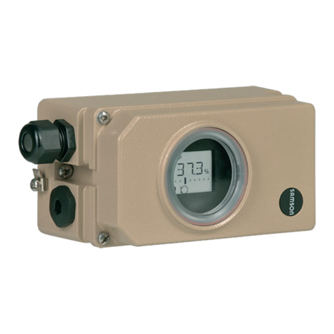
Samson
Samson TROVIS 3730-1 Mounting and operating instructions
Siemens
Siemens SIPART PS2 6DR5 series Compact operating instructions
Infranor
Infranor SMT-BD2/m manual

Pepperl+Fuchs
Pepperl+Fuchs PXV F200-SSI-V19 Series manual
PI
PI M-110.*DG1 series user manual
rotork
rotork TMP-3000 product manual

Lincoln Electric
Lincoln Electric POSIMATIC PS30 Safety instruction for use and maintenance

Samson
Samson 3730 Series Mounting and operating instructions
Azbil
Azbil AVP300 user manual
PI
PI P-587.6CD user manual
Flowserve
Flowserve D20 Series Installation operation & maintenance

