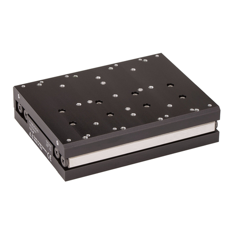
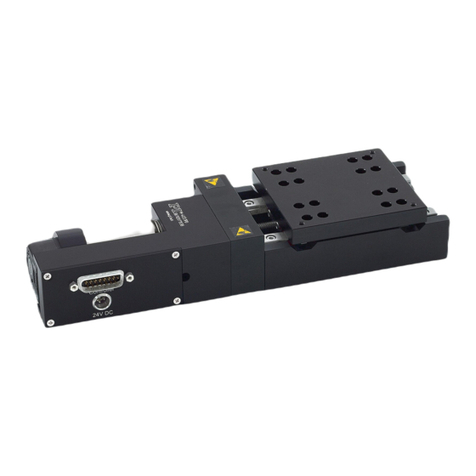
PI M-110.*DG1 series User manual

User Manual
M110T0032-EN, valid for M-110.xxx1 / M-111.xxx1 / M-112.xxx1
MMa 20. September 2018
Physik Instrumente (PI) GmbH & Co. KG, Auf der Roemerstrasse 1, 76228 Karlsruhe, Germany Page 1 / 26
Phone +49 721 4846
M-110.xxx1 / M-111.xxx1 / M-112.xxx1
Microtranslation Stage
User Manual
Micropositioning stage with
HD D-Sub 26
connector, in variants according to:
•Travel range: 5 mm / 15 mm / 25 mm
•Drive screw type: Threaded drive screw /
ball screw
•Gear drive: stepper motor / DC motor

User Manual
M110T0032-EN, valid for M-110.xxx1 / M-111.xxx1 / M-112.xxx1
MMa 20. September 2018
Physik Instrumente (PI) GmbH & Co. KG, Auf der Roemerstrasse 1, 76228 Karlsruhe, Germany Page 2 / 26
Phone +49 721 4846
Contents
Safety 3
Highlighting Safety Instructions........................................................................................................................... 3
Intended Use ....................................................................................................................................................... 3
Basic Safety Instructions...................................................................................................................................... 4
Maximum Ratings................................................................................................................................................ 4
Naming Product and System Components 5
Product Scheme................................................................................................................................................... 5
Further Information on the Product and the System Components .................................................................... 6
Installation and Startup 6
Unpacking/Scope of Delivery .............................................................................................................................. 6
Mechanical Installation ....................................................................................................................................... 7
Mounting the Positioner onto a Surface......................................................................................................................... 7
Mounting the Payload on the Platform ........................................................................................................................11
Electrical Installation ......................................................................................................................................... 12
Connecting the C-663.12, C-863.11, C-863.12 or C-884 Controller .............................................................................. 12
Integration into the Control Software and Initial Test ...................................................................................... 14
Coordinate System / Direction of Motion.....................................................................................................................15
Maintenance, Cleaning, Troubleshooting, and Disposal 16
Maintenance...................................................................................................................................................... 16
Cleaning ............................................................................................................................................................. 16
Troubleshooting ................................................................................................................................................ 17
Moving the Platform by Hand.......................................................................................................................................17
Repair and Warranty ......................................................................................................................................... 18
Disposal ............................................................................................................................................................. 18
Appendix 19
Model Range, Characteristics (Differences) ...................................................................................................... 19
Ambient Conditions and Classifications ............................................................................................................ 19
Data ................................................................................................................................................................... 20
Dimensions ........................................................................................................................................................ 21
HD D-Sub 26 Pin Assignment............................................................................................................................. 22
Options and Additional Accessories .................................................................................................................. 23
Mounting Adapter (Order Separately)..........................................................................................................................23
Adapter Cable for Connecting to the C-863.11 or C-884 Controller ............................................................................. 23
Multi-Axis Systems ........................................................................................................................................................ 23
X/Y Combination Mounting Diagram ............................................................................................................................ 24
X/Z Combination Mounting Diagram (with Mounting Adapter)...................................................................................25
Legal Information .............................................................................................................................................. 26
CE Compliance...............................................................................................................................................................26
Figures, Commitment, Actuality ...................................................................................................................................26
Copyright.......................................................................................................................................................................26
Contact Person, Feedback............................................................................................................................................. 26

User Manual
M110T0032-EN, valid for M-110.xxx1 / M-111.xxx1 / M-112.xxx1
MMa 20. September 2018
Physik Instrumente (PI) GmbH & Co. KG, Auf der Roemerstrasse 1, 76228 Karlsruhe, Germany Page 3 / 26
Phone +49 721 4846
Safety
Highlighting Safety Instructions
CAUTION
Dangerous situation
If not avoided, the dangerous situation will result in minor injury.
Measures for avoiding the risk.
NOTICE
Dangerous situation
If not avoided, the dangerous situation will result in damage to equipment.
Measures for avoiding the risk.
INFORMATION
Information in easier handling, further sources of information etc.
Intended Use
The intended use is precision linear motion and positioning a payload in one direction (x axis).
The product is equipped with a platform for mounting the payload.
The product is intended for indoor use and use in an environment that is free of dirt, oil, and
lubricants.
It is not intended for applications in areas where failure would result in considerable risks for
human beings or the environment.
Use is considered as intended when
-accessories are used from the scope of delivery or additional components (e.g., controller,
power adapters, mounting adapter, control software), which are recommended in this
manual or on our website.
-the constraints and procedures described here are adhered to (intended use, maximum
ratings, ambient conditions, load ranges, settings, process descriptions).

User Manual
M110T0032-EN, valid for M-110.xxx1 / M-111.xxx1 / M-112.xxx1
MMa 20. September 2018
Physik Instrumente (PI) GmbH & Co. KG, Auf der Roemerstrasse 1, 76228 Karlsruhe, Germany Page 4 / 26
Phone +49 721 4846
Basic Safety Instructions
Improper use of the product can cause personal injury and damage to property.
Only use the product for its intended purpose, and only use it if it is in perfect
condition.
Before performing the actions described: Read the corresponding section of the
instructions completely.
Eliminate any faults and malfunctions that are likely to affect safety immediately.
Make sure that all (i.e., also the following) users have access to the user instructions.
The operator is personally responsible for correct installation and operation of the product
described.
INFORMATION
It is not necessary to open the housing either for operation or maintenance.
Loosening screws and opening the housing can adversely affect your safety and the functional
capability of the positioner, and results in loss of warranty.
Maximum Ratings
The following values may not be exceeded; the specified voltage values are not suitable for
continuous operation. Compliance with optimum values is ensured by using the components
and procedures described here.
Model* Maximum
operating voltage
Operating frequency Maximum power
consumption
M-110.xDG1
24 V
0 Hz
0.52 W
M-111.xDG1
M-112.xDG1
1.75 W
M-110.x2S1
M-111.x2S1
M-112.x2S1
48 V **
0 Hz
1.5 W
*For a detailed breakdown, see the appendix
** Do not use for continuous operation!

User Manual
M110T0032-EN, valid for M-110.xxx1 / M-111.xxx1 / M-112.xxx1
MMa 20. September 2018
Physik Instrumente (PI) GmbH & Co. KG, Auf der Roemerstrasse 1, 76228 Karlsruhe, Germany Page 5 / 26
Phone +49 721 4846
Naming Product and System Components
Product Scheme
1Connector for the controller (HD D-Sub 26, connector (m))
2Cable (shorter illustration)
3Cable exit
4Housing
5Drive screw
6Guide
7Platform
8Mounting hole for payload (M3, 6 altogether)
9Mounting hole for mounting the positioner from above (for DIN 7934 M3 screws, 2 altogether)
10 Product labeling area (laser engraving), incl. model designation and serial number
X Direction of motion on positive command in the control software
X

User Manual
M110T0032-EN, valid for M-110.xxx1 / M-111.xxx1 / M-112.xxx1
MMa 20. September 2018
Physik Instrumente (PI) GmbH & Co. KG, Auf der Roemerstrasse 1, 76228 Karlsruhe, Germany Page 6 / 26
Phone +49 721 4846
Further Information on the Product and the System Components
The products (and programs) from PI mentioned here are normally described in more detail
separately (search for the product name on the website to get the user manual).
If instructions are missing or you require further information, contact service@pi.de or contact
your PI subsidiary by telephone.
In addition to the information on the corresponding product page of our website, the following
documents also apply:
MP119EK Short instructions: Positioners with electric motors
Installation and Startup
Unpacking/Scope of Delivery
1. Unpack the positioner with care.
2. Scope of delivery: If parts in the following list are missing or damaged: Contact the
−Positioner
−Extension cable 3 m (K040B0055)
−Mounting screws (4x DIN 7984 M3x6)
−Hex key AF 2 and AF 1.5
−Short instructions (MP119EK)
3. Keep all packaging materials in case the product needs to be returned.

User Manual
M110T0032-EN, valid for M-110.xxx1 / M-111.xxx1 / M-112.xxx1
MMa 20. September 2018
Physik Instrumente (PI) GmbH & Co. KG, Auf der Roemerstrasse 1, 76228 Karlsruhe, Germany Page 7 / 26
Phone +49 721 4846
Mechanical Installation
NOTICE
Protruding screw heads!
Protruding screw heads can damage the positioner.
Make sure that the screws are tightened and recessed completely, and do not interfere
with motion of the platform.
Mounting the Positioner onto a Surface
NOTICE
Warping of the positioner reduces positioning accuracy
Mechanical tension can occur when for example,
•the positioner is mounted on uneven surfaces (flatness > 10 µm)
•the positioner and the surface heat up/cool down at different rates
•the gaps from the mounting holes in the positioner to the surface do not line up
Avoid any mechanical tension.
NOTICE
Unwanted changes in position when mounted vertically or obliquely!
In order for the platform and the setup (payload) to remain at rest when it is switched off, its
weight force component may not exceed the holding force of the drive (10 N) in the
direction of motion.
Lay out the inclination of the surface and the mass of the setup according.
Before startup, check whether the platform moves when the drive is switched off.
INFORMATION
When installing, pay attention to the desired travel range for your payload.
Mounting from above
Tools/accessories
2 mounting screws, DIN 7984 M3x6, in the scope of delivery
Hex key AF 1.5, in the scope of delivery
Hex key AF 2, in the scope of delivery
Surface with holes and M3 thread according to the position of the mounting holes in
the positioner (see fig.); min. depth of 3 mm.

User Manual
M110T0032-EN, valid for M-110.xxx1 / M-111.xxx1 / M-112.xxx1
MMa 20. September 2018
Physik Instrumente (PI) GmbH & Co. KG, Auf der Roemerstrasse 1, 76228 Karlsruhe, Germany Page 8 / 26
Phone +49 721 4846
Position of the holes for mounting from above
Procedure
1. Move the platform with the help of the controller or as follows, by hand so that one
mounting hole can be used:
a) Insert the AF 1.5 hex key into the drive screw inlet.
b) Turn the hex key until the mounting hole is exposed completely.
2. Place the positioner onto the surface so that its mounting holes are in line.

User Manual
M110T0032-EN, valid for M-110.xxx1 / M-111.xxx1 / M-112.xxx1
MMa 20. September 2018
Physik Instrumente (PI) GmbH & Co. KG, Auf der Roemerstrasse 1, 76228 Karlsruhe, Germany Page 9 / 26
Phone +49 721 4846
3. Tighten the mounting screws but do not overtighten.
The head of the screw may not protrude. Otherwise, the platform could be damaged
during motion.
4. Proceed with the second mounting screw according to the above-mentioned steps.
5. Move the platform so that the first mounting screw that was inserted is exposed.
6. Tighten the mounting screws but do not overtighten (max. torque is 1.5 Nm).
7. Repeat steps 5 and 6 accordingly for the remaining screws.
8. Check that the positioner is affixed firmly to the surface.

User Manual
M110T0032-EN, valid for M-110.xxx1 / M-111.xxx1 / M-112.xxx1
MMa 20. September 2018
Physik Instrumente (PI) GmbH & Co. KG, Auf der Roemerstrasse 1, 76228 Karlsruhe, Germany Page 10 / 26
Phone +49 721 4846
Mounting from below
The platform may not be moved when mounting from below.
Tools/accessories
M2 mounting screw. When selecting the screw length, take the length of the screw, the
depth of the hole in the surface and the depth of 4 mm of the inner thread in the base
body into consideration.
Screwdriver respectively hex key according to the screw type selected (hex key AF 1.5 in
the scope of delivery)
Surface with holes corresponding to the geometry shown below.
1. Place the positioner onto the surface so that its mounting holes are in line.
2. Tighten the 4 mounting screws completely.
3. Check that the positioner is firmly attached to the surface.

User Manual
M110T0032-EN, valid for M-110.xxx1 / M-111.xxx1 / M-112.xxx1
MMa 20. September 2018
Physik Instrumente (PI) GmbH & Co. KG, Auf der Roemerstrasse 1, 76228 Karlsruhe, Germany Page 11 / 26
Phone +49 721 4846
Mounting the Payload on the Platform
NOTICE
Excessively long screws!
The positioner can be damaged by screws that are inserted too deeply.
Note the depth of the mounting holes in the platform.
Only use screws with the correct length for the respective mounting holes.
Requirements
The distance between the center of gravity of the payload and the center of the
platform is as small as possible in all directions.
At least two points are provided for mounting the payload on the platform (ideally:
three attachment points).
The position of the mounting holes in the payload and platform match.
Take the inner thread's depth in the platform of 4 mm when choosing the length of the
screw.
Tools and accessories
Mounting screws: At least 2 M3 screws of suitable length
Suitable screwdriver
Procedure
1. Bring the corresponding mounting holes in line for the payload and the platform.
2. Use the mounting screws to affix the payload (tightening torque: Max. 1.5 Nm).
3. Check that the payload is attached firmly to the platform of the positioner.

User Manual
M110T0032-EN, valid for M-110.xxx1 / M-111.xxx1 / M-112.xxx1
MMa 20. September 2018
Physik Instrumente (PI) GmbH & Co. KG, Auf der Roemerstrasse 1, 76228 Karlsruhe, Germany Page 12 / 26
Phone +49 721 4846
Electrical Installation
INFORMATION
Positioners with stepper motor have the letter sequence 2S in the model designation and
must be connected to a controller from the C-663.12 series.
Positioners with DC gear motor have the letter sequence DG in the model designation and
must be connected to ta controller from the C-863.11, C-863.12 or C-884 series. You will
need the C-815.LDM1 adapter cable for the C-863.11 or C-884. This must be ordered
separately.
The C-815.LDM1 adapter cable may not be used for the above-mentioned positioners with
stepper motor.
The connecting cable may only be extended once and only with the extension cable (3 m)
supplied or with a cable specifically recommended.
Only use the controllers and cables recommended by PI!
Connecting the C-663.12, C-863.11, C-863.12 or C-884 Controller
C-663.12 stepper motor controller / C-863.12 DC motor controller
1. Optionally, if the attached cable is not long enough: Connect the positioner's plug
connector to the socket on extension cable. The UNC nuts must be removed from the
plug (turn the knurled screws counterclockwise) before connecting directly to the
controller.
2. Connect the positioner's plug or respectively the extension cable to the "Motor" socket
on the controller.
3. Tighten the screws on all connectors used.

User Manual
M110T0032-EN, valid for M-110.xxx1 / M-111.xxx1 / M-112.xxx1
MMa 20. September 2018
Physik Instrumente (PI) GmbH & Co. KG, Auf der Roemerstrasse 1, 76228 Karlsruhe, Germany Page 13 / 26
Phone +49 721 4846
4. Connect the controller to the corresponding power adapter.
5. Use the power cord to connect the power adapter to the mains supply.
C-863.11 / C-884 DC motor controller
1. Connect the plug on the adapter cable (C-815.LDM1) to the "Motor" socket on the
controller. The UNC nuts must be removed from the plug (turn the knurled screws
counterclockwise) before connecting directly to the controller.
2. Optionally, if the attached cable is not long enough: Connect the socket of adapter
cable to the plug on the extension cable.
3. Connect the positioner's plug to the socket on the extension cable or respectively the
adapter cable.
4. Tighten the screws on all connectors used.
5. Connect the controller to the corresponding power adapter.
6. Use the power cord to connect the power adapter to the mains supply.

User Manual
M110T0032-EN, valid for M-110.xxx1 / M-111.xxx1 / M-112.xxx1
MMa 20. September 2018
Physik Instrumente (PI) GmbH & Co. KG, Auf der Roemerstrasse 1, 76228 Karlsruhe, Germany Page 14 / 26
Phone +49 721 4846
Integration into the Control Software and Initial Test
Requirements
The controller has been connected according to the corresponding user manual and
ready for operation (connected to the power adapter/mains supply and positioner; see
above).
The PIMikroMove® control software has been installed and started according to the
corresponding user manual.
The positioner is already referenced according to the user manual for the controller.
Procedure
INFORMATION
Images are schematic; value setting exemplary.
1. Click the button in the PIMikroMove® (Axes tab) main window to move the platform to
the left ( |< ) or right ( >| ) end of the travel range.
2. Check:
−Does the platform move to the end of the travel range?
−Does the drive stop at end of travel range?
−Does the Target value change accordingly in the main window of the control
software (see above)?
If this is not the case:
Check the electrical installation (see the section "Electrical Installation“, p.12) and the
settings in the control software (see user manual for the Controller) If the error persists,

User Manual
M110T0032-EN, valid for M-110.xxx1 / M-111.xxx1 / M-112.xxx1
MMa 20. September 2018
Physik Instrumente (PI) GmbH & Co. KG, Auf der Roemerstrasse 1, 76228 Karlsruhe, Germany Page 15 / 26
Phone +49 721 4846
Coordinate System / Direction of Motion
The position of the platform at the left end of the travel range corresponds to the zero point.

User Manual
M110T0032-EN, valid for M-110.xxx1 / M-111.xxx1 / M-112.xxx1
MMa 20. September 2018
Physik Instrumente (PI) GmbH & Co. KG, Auf der Roemerstrasse 1, 76228 Karlsruhe, Germany Page 16 / 26
Phone +49 721 4846
Maintenance, Cleaning, Troubleshooting, and Disposal
Maintenance
Maintenance run
If the platform only moves in a limited travel range, we recommend running once over the
entire range with the following intervals (maintenance run). This allows the lubricant to be
distributed evenly over the relevant machine elements.
Type of operation Interval
Laboratory use After 50 operating hours or at least after one 1 year
Continuous industrial
operation
After every 5000 motion cycles
Relubricating
Type of operation Interval
Laboratory use Normally not necessary
Continuous industrial
operation
According to separately agreed maintenance schedule
If you have any questions on relubricating, contact our customer service department
Cleaning
Tools
Soft cloth
Mild cleaning agent or disinfectant
Procedure
INFORMATION
Do not allow the cleaning agent or disinfectant to get onto the drive screw or guides. This
could impair lubrication.
1. Remove the motor cable from the controller.
2. Dampen the cloth with the cleaning agent or disinfectant.
3. Wipe over the dirty surface gently.
4. After cleaning, reconnect the motor cable to the controller and tighten the screws to
secure the plug.

User Manual
M110T0032-EN, valid for M-110.xxx1 / M-111.xxx1 / M-112.xxx1
MMa 20. September 2018
Physik Instrumente (PI) GmbH & Co. KG, Auf der Roemerstrasse 1, 76228 Karlsruhe, Germany Page 17 / 26
Phone +49 721 4846
Troubleshooting
Problem Possible causes Solution
The platform can be
moved slightly; there is
an audible clicking noise
This behavior is design-
related and results from
the (desired) preload of
the drive screw.
- (There is no malfunction. The performance
capability is not impaired.)
Increased wear Warped base body
Determine and eliminate the cause of
mechanical stress in the housing
Pay attention to the recommended surface
flatness that the positioner is mounted on:
<10 µm.
Reduced accuracy
Impairment of the
function after system
modification
Controller was
replaced
Positioner was
replaced by another
model from the
product series
If necessary, reconfigure the assignments from
the controller and positioner in the control
software.
The stage no longer
moves
The platform has got stuck
at the end of the travel
range (hard stop).
Move the platform by hand (see below).
If the problem that occurred with your system is not listed in the table above or cannot be
Moving the Platform by Hand
Tools
Hex key AF 2
Procedure
You can move the platform by hand by turning the drive screw.
1. Insert a hex key into the drive screw inlet (see fig.).
2. Turn the hex key (anti)clockwise.
−Clockwise: Platform moves away from the cable exit.
−Anticlockwise: Platform moves towards the cable exit.

User Manual
M110T0032-EN, valid for M-110.xxx1 / M-111.xxx1 / M-112.xxx1
MMa 20. September 2018
Physik Instrumente (PI) GmbH & Co. KG, Auf der Roemerstrasse 1, 76228 Karlsruhe, Germany Page 18 / 26
Phone +49 721 4846
Repair and Warranty
In the case of malfunction or failure:
Do not try to repair the positioner yourself.
Contact our customer service department ([email protected]).
You will find the positioner's exact model designation and serial number in the laser
engraving (see fig.).
For return shipment: If possible, return the entire contents of the scope of delivery and
in the original packaging.
Disposal
In accordance with EU law, electrical and electronic equipment may not be disposed of in EU
member states via the municipal residual waste.
Dispose of your old equipment according to international, national, and local rules and
regulations.
In order to fulfil the responsibility as the product manufacturer, PI undertakes environmentally
correct disposal of all old PI equipment made available on the market after 13 August 2005
without charge.
Any old PI equipment can be sent free of charge to the following address:
Physik Instrumente (PI) GmbH & Co. KG
Auf der Roemerstrasse 1
76228 Karlsruhe, Germany

User Manual
M110T0032-EN, valid for M-110.xxx1 / M-111.xxx1 / M-112.xxx1
MMa 20. September 2018
Physik Instrumente (PI) GmbH & Co. KG, Auf der Roemerstrasse 1, 76228 Karlsruhe, Germany Page 19 / 26
Phone +49 721 4846
Appendix
Model Range, Characteristics (Differences)
All models with HD D-Sub 26 connector (plug)
Model Travel range Drive screw Motor
(with gearhead)
5 mm 15 mm 25 mm Thread Recircu-
lating ball
bearing
DC motor Stepper
motor
M-110.1DG1 + + +
M-110.12S1 + + +
M-110.2DG1 + + +
M-110.22S1 + + +
M-111.1DG1 +
+
+
M-111.12S1
+
+
+
M-111.2DG1
+
+
+
M-111.22S1
+
+
+
M-112.1DG1
+
+
+
M-112.12S1
+
+
+
M-112.2DG1
+
+
+
M-112.22S1
+
+
+
See the data table (below) for other model-specific characteristics.
Ambient Conditions and Classifications
Area of application For indoor use only
Maximum altitude 2000 m
Relative humidity Max. 80 % for temperatures up to 31 °C
Decreasing linearly to 50 % at 40 °C
Storage temperature -20 °C to 65 °C
Transport temperature -20 °C to 65 °C
Supply fluctuations Max. ±10 % of the nominal voltage
Degree of pollution 2
Degree of protection according to IEC 60529 IP40

User Manual
M110T0032-EN, valid for M-110.xxx1 / M-111.xxx1 / M-112.xxx1
MMa 20. September 2018
Physik Instrumente (PI) GmbH & Co. KG, Auf der Roemerstrasse 1, 76228 Karlsruhe, Germany Page 20 / 26
Phone +49 721 4846
Data
Measured values valid for 20 ±3 °C.
If there is an updated datasheet, it will be made available on our website.
M-110.1DG1 /
M-111.1DG1 /
M-112.1DG1
M-110.12S1 /
M-111.12S1 /
M-112.12S1
M-110.2DG1 /
M-111.2DG1 /
M-112.2DG1
M-110.22S1 /
M-111.22S1 /
M-112.22S1
Unit Tole–
rance
Motion and positioning
Travel range 5 / 15 / 25 5 / 15 / 25 5 / 15 / 25 5 / 15 / 25 mm
Integrated sensor Rotation
encoder
Rotation
encoder
Design resolution* 0.0069 0.00029 0.0086 0.00036 µm
Minimum incremental
motion*
0.05 0.02 0.2 0.2 µm
Backlash 3
3
3
3
µm
Unidirectional repeatability 0.25 0.25 0.15 0.15 µm
Velocity 1 / 1.5 / 1.5 1 / 1 / 1 1.5 / 2 / 2 1 / 1 / 1 mm/s max.
Mechanical properties
Drive screw Drive screw Drive screw Ball screw Ball screw
Drive screw pitch 0.4 0.4 0.5 0.5 mm
Gear ratio 256:9 256:9 256:9 256:9
Motor resolution 24 24 Full
steps/r
ev.
Load capacity 30 / 30 / 20 30 / 30 / 20 30 / 30 / 20 30 / 30 / 20 N max.
Push/pull force 10 10 10 10 N max.
Holding force 10 10 10 10 N max.
Permissible lateral force 15 / 10 / 10 15 / 10 / 10 15 / 10 / 10 15 / 10 / 10 N max.
Drive properties
Motor type DC gearhead
motor
2-phase
stepper motor
DC gearhead
motor
2-phase
stepper motor
Operating voltage 0 to ±12 0 to ±12
Motor power 0.52 / 1.75 /
1.75
1.5 0.52 / 1.75 /
1.75
1.5 W
Reference and limit
switches
Hall effect Hall effect Hall effect Hall effect
This manual suits for next models
5
Table of contents
Other PI Valve Positioner manuals
Popular Valve Positioner manuals by other brands

Parker
Parker Daedal 400LXR Series product manual

Ytc
Ytc YT-1000L installation manual

ERIKS
ERIKS ECON 3300 NCS Series Installation & operating manual

VAC
VAC V200 POSITIONER Installation, Calibration and Troubleshooting Manual

EBRO ARMATUREN
EBRO ARMATUREN SBU IO-Link quick guide

Ytc
Ytc YT-2700 Series user manual