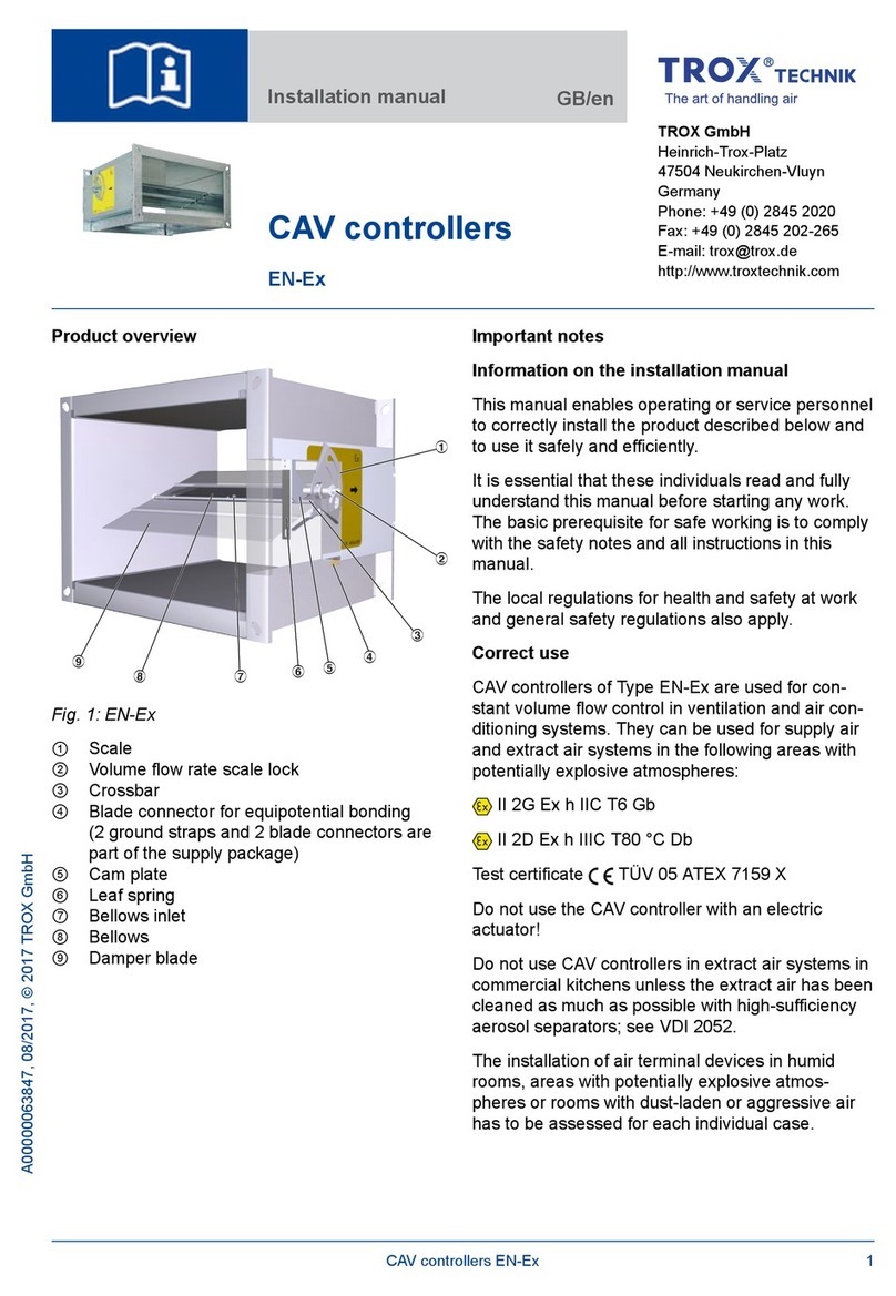
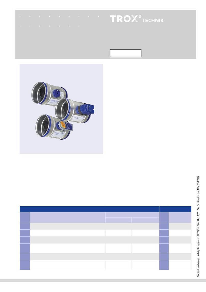
Trox EASYLAB TCU3 Series User manual

EASYLAB controller
Serie TCU3
Installation and operating manual GB/en

M375EV0, 2, GB/en
© TROX GmbH 2017
TROX GmbH
Heinrich-Trox-Platz
47504 Neukirchen-Vluyn
Germany
Telephone: +49 (0) 2845 202-0
Fax: +49 (0) 2845 202-265
E-mail: [email protected]
Internet: www.trox.de
06/2019
EASYLAB controller Serie TCU3
2

1 General information................................... 4
2Safety and correct use.............................. 6
General safety notes.................................... 6
Correct use.................................................. 7
Incorrect use................................................ 7
Residual risks............................................... 7
3 Technical data............................................ 8
4 Transport, storage and packaging......... 10
Delivery check............................................ 10
Transport on site........................................ 10
Storage...................................................... 10
Packaging.................................................. 10
5 Product description................................. 11
Volume flow control.................................... 11
Volume flow rate monitoring....................... 11
Pressure monitoring................................... 11
Shut-off monitoring..................................... 11
External signaling of setpoint deviation..... 12
Interfaces and signal lamps on the con-
troller casing............................................... 13
Interfaces and signal lamps in the con-
troller casing............................................... 15
6 Installation................................................ 17
Tube connection on the pressure trans-
ducer.......................................................... 20
7 Wiring........................................................ 20
Safety instructions...................................... 20
Notes on wiring.......................................... 21
Additional information on wiring................. 21
Limited voltage supply............................... 21
Polarity of the power supply....................... 21
Functional earth......................................... 21
Strain relief................................................. 21
Cabling....................................................... 21
8 Commissioning........................................ 22
9 Maintenance............................................. 25
Safety......................................................... 25
Operation and maintenance...................... 25
Zero point correction.................................. 25
Replacing the fuse..................................... 25
10 Decommissioning.................................... 26
Removing the electronic controller............. 26
11 Appendix................................................... 27
Table of contents
EASYLAB controller Serie TCU3 3

1 General information
About this manual
This manual enables operating and service per-
sonnel to correctly install the EASYLAB TCU3 con-
troller and to use it safely and efficiently.
The TCU3 electronic controller is used with a VAV
terminal unit; both products together form a func-
tional unit.
Depending on the scope of order, the electronic
controller can be equipped with optional expansion
modules (EM-xx) at the factory (retrofitting pos-
sible).
This operating and installation manual is intended
for use by fitting and installation companies, in-
house technicians, technical staff, instructed per-
sons, and qualified electricians or air conditioning
technicians.
It is essential that these individuals read and fully
understand this manual before starting any work.
The basic prerequisite for safe working is to comply
with the safety notes and all instructions in this
manual.
The local regulations for health and safety at work
and general safety regulations also apply.
This manual must be given to the system owner
when handing over the system. The system owner
must include the manual with the system documen-
tation. The manual must be kept in a place that is
accessible at all times.
Illustrations in this manual are mainly for informa-
tion and may differ from the actual design. Discrep-
ancies cannot be used to make any claims against
the manufacturer.
In addition to this manual, the following documents
apply
Operating manual
– EasyConnect configuration software
Installation manual for VAV terminal unit(s)
Installation manuals for EASYLAB components
– Expansion module EM-AUTOZERO
– Expansion module EM-LIGHT
– Expansion module EM-TRF/EM-TRF-USV
– Expansion module EM-LON
– Expansion module EM-BAC-MOD
– Expansion module EM-BAC-IP
– Control panel BE-LCD
– Control panel BE-SEG
– Face velocity transducer VS-TRD
– Sash distance sensor DS-TRD
General wiring documents
Project-specific wiring documents
All documents can be downloaded from
www.troxtechnik.com.
Project-specific information is provided together
with the order confirmation or delivered together
with the product.
TROX Technical Service
To ensure that your request is processed as quickly
as possible, please keep the following information
ready:
Product name
TROX order number
Delivery date
Brief description of the fault
Online www.troxtechnik.com
Phone +49 2845 202-400
General information
EASYLAB controller Serie TCU34

Limitation of liability
The information in this manual has been compiled
with reference to the applicable standards and
guidelines, the state of the art, and our expertise
and experience of many years.
The actual scope of delivery may differ from the
information in this manual for bespoke construc-
tions, additional order options or as a result of
recent technical changes.
The obligations agreed in the order, the general
terms and conditions, the manufacturer's terms of
delivery, and the legal regulations in effect at the
time the contract is signed shall apply.
Defects liability
For details regarding defects liability please refer to
Section VI, Warranty Claims, of the Delivery and
Payment Terms of TROX GmbH.
The Delivery and Payment Terms of TROX GmbH
are available at www.troxtechnik.com.
Copyright
This document, including all illustrations, is pro-
tected by copyright and pertains only to the corre-
sponding product.
Any use without our consent may be an infringe-
ment of copyright, and the violator will be held liable
for any damage.
This applies in particular to:
Publishing content
Copying content
Translating content
Microcopying content
Saving content to electronic systems and
editing it
Safety notes
Symbols are used in this manual to alert readers to
areas of potential hazard. Signal words express the
degree of the hazard.
Comply with all safety instructions and proceed
carefully to avoid accidents, injuries and damage to
property.
DANGER!
Imminently hazardous situation which, if not
avoided, will result in death or serious injury.
WARNING!
Potentially hazardous situation which, if not
avoided, may result in death or serious injury.
CAUTION!
Potentially hazardous situation which, if not
avoided, may result in minor or moderate injury.
NOTICE!
Potentially hazardous situation which, if not
avoided, may result in property damage.
ENVIRONMENT!
Environmental pollution hazard.
Safety signs on the controller
The following symbols and signs are usually found
in the work area. They apply to the very location
where they are found.
General information
EASYLAB controller Serie TCU3 5

Electric shock hazard!
Disconnect the power supply before you open the
device.
Only skilled qualified electricians are allowed to
work in areas marked as having electrical voltage.
Unauthorised persons must not enter areas, open
cabinets or work on components where an elec-
trical voltage is present and which are hence
marked with this symbol.
General warning
Read the operating and installation manual before
commissioning and before you open the casing.
Functional earth
WARNING!
Danger due to illegible signage!
Over time, stickers and signs may fade or
become otherwise illegible, meaning that hazards
cannot be identified and necessary operating
instructions cannot be followed. There is then a
risk of injury.
– Ensure that all of the safety, warning and
operating information is clearly legible.
– Replace illegible signs or stickers immedi-
ately.
2 Safety and correct use
General safety notes
DANGER!
Risk of injury from the damper blade of the
VAV terminal unit
The damper blades of VAV terminal units close or
open extremely quickly (∡ 90° within 3 seconds)
and may crush your hands and arms.
Connect ducts to both ends of a VAV terminal
unit; if one end cannot be ducted, at least fit a
perforated plate to prevent people from reaching
into the terminal unit.
CAUTION!
Risk of injury from the casing cover falling
shut
An open casing cover may suddenly fall shut and
crush your fingers.
–Secure an open casing cover with a bracket.
– Wear protective gloves.
NOTICE!
Risk of damage to property due to large tem-
perature differences
If any electronic components have been kept in
an unheated area, condensation may form and
damage the electronic components beyond
repair.
– Before you start commissioning, make sure
that all devices have warmed up to ambient
temperature. Only after about 2 hours will
the system have reached room temperature.
Safety and correct use
EASYLAB controller Serie TCU36

NOTICE!
Risk of damage to property due to electro-
static charge
Electrostatic charge can damage the electronics.
–Avoid skin contact with any components or
printed circuits.
– Touch an equipotentially bonded metal sur-
face before you touch any printed circuit
boards.
– Wear conductive footwear and antistatic
clothing.
NOTICE!
In an emergency
Immediately disconnect the power supply to the
controller. Emergencies include, for example, a
damaged mains cable, a damaged casing, the
ingress of a liquid or foreign matter, a smell or
smoke.
Have the device checked by the manufacturer
before you put it into operation again.
Correct use
Only use the device for its intended correct use and
in compliance with the safety precautions and infor-
mation in this manual in order to avoid danger to
persons and property.
The correct use of this device encompasses:
The electronic control of volume flow rates for
supply or extract air and for fume cupboards in
combination with a TROX air terminal unit.
Indoor use for ventilation and air conditioning
systems, especially for laboratories.
The controller is typically used in a group of
several controllers for complete room control,
but it may also be used as a single controller.
For error-free operation, the installation orien-
tation of the controller must be observed; pos-
sible installation orientations are indicated on
the installation orientation label on the device.
Incorrect use
Do not use the controller in an installation orienta-
tion or for areas of application that are not
described in this manual.
Do not use the controller outdoors, in wet areas, or
in areas with potentially explosive atmospheres.
Residual risks
Power failure
If the power fails, the damper blade of the VAV ter-
minal unit remains in the position at that time; the
controller will resume operation once power returns.
For safety related applications you may use expan-
sion module EM-TRF-USV, which ensures uninter-
ruptible power supply. If the emergency power unit
has been correctly connected and charged, it will
supply power for the set operating times (ÄTech-
nical Data for EM-TRF-USV).
Monitoring function
Alarm signal in the event of insufficient volume
flow rate,
Ä
on page 11
Alarm signal in the event of insufficient room
pressure,
Ä
on page 11
Alarm signal in the event of volume flow rate in
shut-off position,
Ä
on page 11
For safety related applications you should check
whether then safety measures are required, such
as alarms. You may use the alarm relay for
switching operations.
Safety and correct use
EASYLAB controller Serie TCU3 7

3 Technical data
Technical data
Supply voltage 24 V AC ±15% 50-60 Hz
24 V DC ±15%
Do not use 24 V AC and 24 V DC power supplies at the same time!
Optional: 230 V AC mains supply, only with the EM-TRF expansion module; optional: 230 V AC
mains supply with UPS, only with the EM-TRF USV expansion module
Power rating The maximum power required depends on the construction of the controller. Typical construc-
tions with different equipment result in the following values:
Fume cupboard controller with control panel
Room controller
Room controller with room control panel
Including all expansion modules
35 VA
29 VA
33 VA
40 VA max.
Connecting cable Double-stack terminal blocks for cables with a cross section up to 2.5 mm²
The 24 V supply voltage may be connected for a maximum of 5 controllers.
Micro fuse 2.5 A, slow blow, 250 V, as glass fuse 5 x 20 mm
Volume flow rate
measurement
Differential pressure transducer with room air induction to protect the measurement point
Optional: Automatic zero point correction only with expansion module EM-AUTOZERO
Actuator Fast-running high-precision actuator, ∡ 90°: 3 s
Flow rate setting time ≤ 2 s, depending on duct pressure
Controller recovery
time after supply
voltage failure
< 500 ms
Plug and play commu-
nication system
With automatic detection of the connected equipment and equipment functions:
Communication cable: 300 m max.
Number of controllers: max. 24 per segment
Temperature range Operation: 0 to +50 °C
Storage: -10 to +70 °C
Humidity <90% no condensation
Area of application Enclosed spaces
Protection level IP20
IEC protection class III (protective extra-low voltage)
Technical data
EASYLAB controller Serie TCU38

Dimensions
Fig. 1: Dimensions
①Keep clear to provide access
1When combined with TAM, TVRK, TVR, TVA, TVZ, TVJ or TVT
Technical data
EASYLAB controller Serie TCU3 9

4 Transport, storage and packaging
Delivery check
Check delivered items immediately after arrival for
transport damage and completeness. In case of any
damage or an incomplete shipment, contact the
shipping company and your supplier immediately.
A complete shipment includes:
Electronic controller in a closed two-part
casing, including:
– Bracket for the cover
– 2 cable glands, plastic (black)
– 2 cable clips for strain relief (reusable)
– Flow rate transducer (with tubes con-
nected)
– 2-pin plug connector for connection X1
– 3-pin plug connector for connection X5
(sensor AI)
– Network patch cable, 5 m, S-FTP green
(only for fume cupboard controllers,
equipment function FH-xxx)
Expansion modules as ordered (see delivery
note)
Operating and installation manual
TCU3 is usually factory mounted to a TROX VAV
terminal unit.
If any expansion modules have been ordered, the
controller is factory fitted with these modules and
shipped as a complete unit.
Transport on site
If possible, take the controller in its transport
packaging up to the installation location.
Do not remove the protective wrapping until
just before installation.
Storage
For temporary storage please note:
Leave the device in its packaging and do not
expose it to the effects of weather.
Store the product in a dry place and away from
direct sunlight
Temperature -10 to +70 °C, humidity 90% max.
(no condensation)
Packaging
Properly dispose of packaging material.
Transport, storage and packaging
EASYLAB controller Serie TCU310

5 Product description
Volume flow control
Fig. 2: Example
1 VAV terminal unit, e.g. TVR
2 Differential pressure sensor
3 Electronic controller TCU3
4 Actuator
5 Sticker showing installation orientations
The electronic controller is used in combination with
an air terminal unit to control variable supply or
extract air volume flow rates or for room pressure
control.
The controller includes a diaphragm pressure trans-
ducer that transforms the differential pressure
(effective pressure) into an electric signal. The con-
troller compares the actual value with the setpoint
value and alters the control signal of the actuator if
there is a difference between the two values.
Volume flow rate monitoring
The controller monitors the volume flow rate. If the
actual value deviates by more than 4% (can be con-
figured) from the setpoint value, a signal is emitted:
The red LEDs (on opposite sides of the con-
troller casing) blink continuously.
The alarm relay of the controller drops out
(wire break-proof).
If necessary, external alarm signal
Ä
External
signaling of setpoint deviation
Pressure monitoring
The target pressure is monitored by the controller, if
the actual value deviates from the configured pres-
sure deviation, the following signal is emitted:
The red LEDs (on opposite sides of the con-
troller casing) blink continuously.
The alarm relay of the controller drops out
(wire break-proof).
If necessary, external alarm signal
Ä
External
signaling of setpoint deviation
Shut-off monitoring
The controller monitors the damper blade position;
if a volume flow is detected although the damper
blade is in shut-off mode (override control), an
alarm is emitted:
The red LEDs (on opposite sides of the con-
troller casing) blink continuously.
The alarm relay of the controller drops out
(wire break-proof).
If necessary, external alarm signal
Ä
External
signaling of setpoint deviation
Product description
EASYLAB controller Serie TCU3 11

External signaling of setpoint deviation
The monitoring signals can be forwarded externally
(only with optional equipment)
Monitoring of volume flow rate or room pres-
sure
Display on the control panel (BE-SEG and/or
BE-LCD):
–Red light and sound (flow rate below set-
point)
– Yellow light (flow rate above setpoint)
Signaling to the higher-level system (only with
expansion module EM-LON, EM-IP or EM-
BAC-MOD)
Monitoring shut-off:
Display on the control panel (BE-SEG and/or
BE-LCD):
– Yellow light (flow rate above setpoint)
Signaling to the higher-level system (only with
expansion module EM-LON, EM-IP or EM-
BAC-MOD)
When installed, the controller is usually not acces-
sible and the LEDs are not visible; for safety related
applications, however, signals should be made
visible (with an alarm relay, by others).
Product description
EASYLAB controller Serie TCU312

Interfaces and signal lamps on the controller casing
Fig. 3: Controller casing
Status LEDs
No. Colour Name LED Description
1 Red Error LED on Up to 3 s: Switch-on procedure. Permanently: Switch-on
procedure error
LED blinking Error; for detailed diagnosis use EasyConnect software
LED blinking slowly Undefined equipment function; for detailed diagnosis
use EasyConnect software
LED off Normal operation; if no. 5 is also off ⇒ Equipment not
ready for operation
2 Yellow Cable termina-
tion
LED on Cable termination is active
LED off Cable termination is inactive
3 Green Not used
4 Yellow Data reception
in progress
LED on Data is being received from several controllers
LED on with brief inter-
ruptions
Data is being received from few controllers
LED off No data reception from other devices
5 Green Controller opera-
tion (heartbeat)
LED blinking slowly Normal controller operation
LED flickering Controller operation; PC communication with EasyCon-
nect configuration/diagnosis software
LED off Device not ready
Product description
EASYLAB controller Serie TCU3 13

External interfaces
No. Name Connection
point for
Description
6 Contact 500 mm
(X1)
Sash Connection for a volt-free switch contact used to monitor the maximum
operational sash opening (to EN 14175, only for fume cupboard controllers)
7 Terminal-1 (X2) Control panel 1 Connection point for:
EasyLAB control panel, e.g. type BE-SEG-xx, BE-LCD-01
PC with EasyCONNECT software with
–BlueCon adapter
– Special configuration cable
Terminal-2 (X3) Control panel 2
8 Actuator (X4) Actuator The damper actuator is factory fitted if the actuator is part of the supply
package (not for TAM).
9 Sensor (X5) Analogue input
AI5
On a fume cupboard controller: Equipment function FH-VS ⇒ face velocity
transducer; can otherwise be used for the connection of variable extract air
or supply air volume flows with a 0-10 V DC signal. (Characteristic can be
configured)
10 Comm-1 (X6) Communication 1 RJ45 socket for SF-UTP network patch cables
Comm-2 (X7) Communication 2
11 Fume cupboard
lighting
230 V AC socket, switching with control panel Only for use with expansion
module EM-LIGHT.
Max. switch rating of TCU3 relays: 250 V AC 8 A; switch-on current 12 A.
For details on the electrical data for each connection see
Ä
Appendix ‘List of terminal connections’ on page 29
Product description
EASYLAB controller Serie TCU314

Interfaces and signal lamps in the controller casing
Fig. 4: Interfaces and signal lamps on the PCB
No. Name Description
1 Valve connection Connection point for expansion module EM-AUTOZERO
2 Analogue input 1 (AI1) Connection point for the integral diaphragm pressure transducer, analogue voltage
0-10 VDC, 10 mA max.
3 Expansion slot 1 (ESP-
KOM)
Connection for expansion modules to connect the controller to higher-
level systems:
EM- LON: BUS communication LonWorks FT10
EM-BAC-MOD: BUS communication BACNet MS/TP or MODBUS
RTU
EM-IP: BUS communication BACnet IP or MODBUS IP as well as
web server
4 Power 24 V LED on 24 V supply voltage OK
Product description
EASYLAB controller Serie TCU3 15

No. Name Description
LED off 24 V supply voltage failed / sagging
5 Connection of mains
supply
Connection for EM-TRF and EM-TRF-USV expansion modules
6 Status display for digital
inputs DI1…DI6
LED on Digital input DI is active
LED off Digital input DI is not active
7 Status display for digital
outputs DO1…DO6
LED on Digital output DO is active
LED off Digital output DO not active
8 Terminal block DO1…DO6 Digital outputs 1...6 Changeover relays
max. 250 V AC 8 A, switch-on current 12 A max.
9 Terminal block, 24 V Supply voltage 24 V AC or 24 V DC
Do not use 24 V AC and 24 V DC power supplies at the same time!
10 Terminal block AO1... AO3 Analogue outputs 1...3 Can be configured for 0-10 V DC, 10 mA max.
11 Terminal block DI2…DI6 Digital inputs 2...6 For volt-free switch contacts 5 V DC xx mA
12 Terminal block TI1 Input for temperature sensor PT1000 (only for fume cupboards from software version
V8)
Input for temperature sensor PT1000 (not supported)
13 Terminal block AI1…AI4 Analogue inputs 1...4 Can be configured for 0-10 V DC, 10 mA max.
14 Clip / connection Strain relief / connection for communication cable shield
15 Functional earth Connection point for the functional earth to improve electromagnetic compatibility
(EMV)
16 COMM-1 connection
COMM-2 connection
Alternative terminals for the communication cable; in general, however, connection
points Comm-1 (X6) and Comm-2 (X7) should be used (
Ä
on page 13/10).
SF-UTP network cable
17 COMM terminal resistor Switch ON Communication cable termination is active
Switch OFF Communication cable termination is inactive
18 Terminal 3 Connection for TROX HPD actuator
Do not connect PD here
For details on the electrical data for each connection see
Ä
‘List of terminal connections’ on page 29
Product description
EASYLAB controller Serie TCU316

6 Installation
Installation orientation
The installation orientation of the controller is critical
because of the diaphragm pressure transducer;
approved installation orientations are shown on a
sticker (Fig. 5) on the controller casing.
Fig. 5: Sticker showing the installation orientation
Installation orientation OK
Installation orientation not OK
Install the controller only as follows:
On horizontal ducts (left side of the sticker)
–Only on the side of a duct
Do not install the controller above or
below a duct and neither anywhere in
between.
On vertical ducts (right side of the sticker)
– Any installation orientation
Alternative installation orientation
The installation orientations shown on the sticker
apply to the controller at the time of shipping.
They depend on the position of the diaphragm
pressure transducer in the controller casing. If
you install the controller above or below a duct,
you have to adapt the position of the diaphragm
pressure transducer
Ä
17.
Alternative installation position of the dia-
phragm pressure transducer
Fig. 6: Original position of the diaphragm pressure
transducer at the time of shipping
The diaphragm pressure transducer (Fig. 6/1) and
its holder (Fig. 6/2) are factory fitted in such a way
that the installation orientations of the controller cor-
respond to the sticker.
If necessary, you can adapt the controller for instal-
lation above or below a duct. To do so, you have to
turn the diaphragm pressure transducer by 90°.
1. Grasp the diaphragm pressure transducer
together with the holder and carefully lift it
out of the casing. Be careful so as not to
kink the pneumatic measuring tubes or to
inadvertently disconnect any wires or
cables.
Installation
EASYLAB controller Serie TCU3 17

2. Turn the diaphragm pressure transducer by
90°.
3. Insert the holder with the diaphragm pres-
sure transducer again.
If the position of the diaphragm pressure
transducer has been adapted, the con-
troller must not be installed on the side of
horizontal or vertical ducts.
Fig. 7: Tubing
4. Check all connections and make sure that
the tubes and wires of the transducer are
properly connected and have not been
kinked.
Connect any disconnected wires on the
PCB:
Valve (1) - Connection to ‘Valve’
(Fig. 4/1)
Diaphragm
pressure
transducer (2)
- Connection to
‘Transducer’ (Fig. 4/2)
Replace loosened tubing:
Blue tube - Connection to – (Minus)
transparent tube - Connection to + (Plus)
Installation
EASYLAB controller Serie TCU318

Wall installation
For restricted spaces you can detach the controller
from the VAV terminal unit and install it on the wall
next to the terminal unit or anywhere else nearby; to
fix the controller on a wall, you can use a mounting
bracket (Part no. E346GL3).
Do not extend the actuator cable or any measuring
tubes.
Be sure to install the controller according to the
sticker showing the correct installation orientations
Ä
17.
Fig. 8: Detaching the controller
1. Use a screwdriver to flip up the lug (1) and
lift the controller.
In some cases, e.g. with TVLK, the controller
is factory fitted to the terminal unit without a
bracket.
2. Use suitable screws ∅ 4 mm to fix the
mounting bracket to the wall.
3. Press the controller casing as shown onto
the mounting bracket until it clicks into place.
Installation
EASYLAB controller Serie TCU3 19

Tube connection on the pressure transducer
Room pressure control – supply air
Measuring
point
Tube connection PT699
Positive
Room pressure
Negative
Room pressure
1 + –
2 – +
Room pressure control – extract air
Measuring
point
Tube connection PT699
Positive
Room pressure
Negative
Room pressure
1 + –
2 – +
7 Wiring
Safety instructions
Personnel:
Skilled qualified electrician
DANGER!
Danger of death due to electric current!
Danger of electric shock! Do not touch any live
components!
–Switch off the supply voltage and secure it
against being switched on accidentally
before working on the unit.
– Ensure that no voltage is present.
– Work on the electrical system must only be
carried out by skilled qualified electricians.
CAUTION!
Risk of damage to the controller
For wiring please note:
–Do not connect the 24 V supply if the EM-
TRF or EM-TRF-USV expansion module has
been installed.
– Do not connect 230 V and 24 V supply vol-
tages at the same time.
– Do not connect Terminals 1 + 2 with
Comm 1 + 2.
– Never connect 24 V AC and 24 V DC supply
voltage at the same time.
– Never connect the PC or Comm 1 + 2 to the
connection (Fig. 4/18 - Terminal 3).
Wiring
EASYLAB controller Serie TCU320
Table of contents
Other Trox Controllers manuals
Popular Controllers manuals by other brands
Texas Instruments
Texas Instruments bq34z100 user guide
Siemens
Siemens SIRIUS 3RW40 5 Original operating instructions
Avlite
Avlite AV-OL-CTRL-T3 Installation & service manual
Panasonic
Panasonic EYFRZ01 operating instructions
Garnet
Garnet SPILLSTOP ULTRA 815-UHP/H user manual
Pakton
Pakton JVA Z Series user manual
