Garnet SPILLSTOP ULTRA 815-UHP/H User manual
Printed in Canada
www.garnetinstruments.com
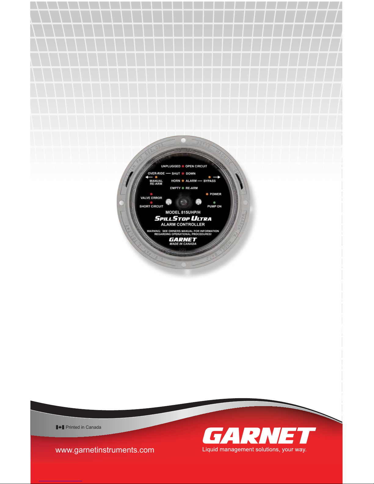
MODEL 815-UHP/H
HYDRAULIC VERSION
MANUAL
SPILLSTOP ULTRA
TM
Alarm Controller with
Hose Protection
Overll Prevention System

Page 2 815UHP/H Manual
Table of Contents
CHAPTER 1 - OVERVIEW.............................................................................................3
CHAPTER 2 - FEATURES AND OPERATION..........................................................4
CHAPTER 3 - INSTALLATION GUIDE.......................................................................8
CHAPTER 4 - WIRING DIAGRAMS......................................................................... 10
CHAPTER 5 - TROUBLESHOOTING GUIDE......................................................... 12
CHAPTER 6 - SERVICE AND WARRANTY INFORMATION............................ 13
MAIL IN WARRANTY ................................................................................................. 15
GARNET
SPILLSTOP ULTRA
TM
Hose Protection
Overll Prevention System
MODEL 815-UHP/H
HYDRAULIC VERSION MANUAL
815-UHP/H_v8.4 - 04-Sep-2018

Page 3815UHP/H Manual
Congratulations on purchasing the Garnet Instruments
Model 815UHP/H SPILLSTOP ULTRA™ Hose Protection Overll
Prevention System. The 815UHP/H represents the state of the art
in spill control for crude oil and chemical hauling. The SPILLSTOP™
is designed to work in conjunction with a Garnet Model 810PS2
SEELEVEL PROSERIES
™ or a Model 808P2
SEELEVEL SPECIAL
™ system
to assist the truck operator with truck tank overll protection in
applications where the uid is loaded with a hydraulic pump or
an external pump. In addition to the tank overll protection, the
815UHP/H also assists in preventing spills due to blown hoses.
The 815UHP/H system is designed as an emergency backup
system. The operator should still be responsible for loading and
unloading of the tank, but in the event that the operator is unable
to shut down loading when the tank is full or makes an occasional
error, the 815UHP/H system can prevent a spill and damaged
equipment.
The 815UHP/H is easy to install and operate, and is designed to
withstand the rigors of mobile applications. The Model 817 Truck
Gauge Programmer is used to set the alarm points in the 810PS2
SEELEVEL PROSERIES
™ or the 808P2
SEELEVEL SPECIAL
™ gauge, which
are programmed with the horn alarm and shutdown points. The
system can shut down hydraulically operated loading pumps. A
horn alarm is provided to warn of an impending full tank condition.
CHAPTER 1 - OVERVIEW
Page 4 815UHP/H Manual
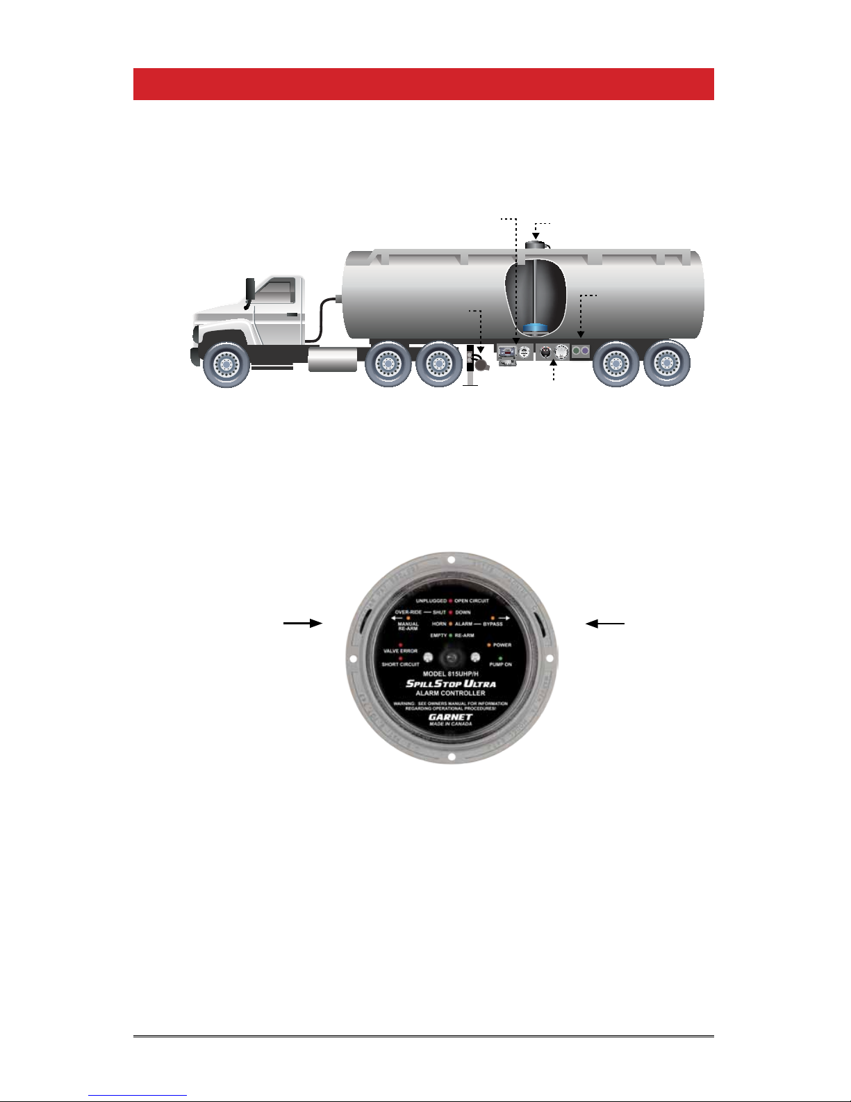
The following diagram shows the basic components and
connections of the 815UHP/H for a tractor trailer application.
MODEL815UD
DUALALARMCONTROLLER
WARNING:SEEOWNERSMANUALFORINFORMATION
REGARDINGOPERATIONALPROCEDURES!
SPILLSTOPULTRA
TM
UNPLUGGED
SHUTDOWN
HORNALARM
TANKEMPTY
RE-ARM
SHORTCCT
PUMP ON
REARFRONT
PERMIT
THERMB
OPTIC
THERMA
MODEL688
OPTIC/THERMISTORLOADINGRACKCONTROLLER
MultiRackTM
POWER
OPTIC
SIGNAL
810-X Bar
Hydraulic Pump
815UHP SPILLSTOP
Controller and
688 MULTIRACK
Rack Plugs Wired
to MULTIRACK
808P2 SEELEVEL SPECIAL
or 810PS2 SEELEVELPROSERIES 2
The SPILLSTOP controller works in conjunction with alarm signals
sent by the 808P2 or 810PS2 level gauges and hose pressure
sensors.
The 815UHP/H alarm controller monitors and displays the alarm
status of the gauge, the the loading valve status, and the horn
bypass status. Wiring faults between the controller and gauge are
also monitored. The controller activates a warning horn and shuts
off the hydraulic pump if the uid level in the tank reaches the full
point. In addition, if an attempt is made to pump against a closed
valve, or overll the tank, loading is shut down. Each 815UHP/H
controller accommodates one compartment.
WARNING: The 815UHP/H is intended as an emergency backup
system only, and is not intended as a substitute for operator
diligence during the loading process.
CHAPTER 2 - FEATURES AND OPERATION
Horn Alarm
Bypass Button
Over-ride and
Manual Re-arm Button

Page 5815UHP/H Manual
The operation of the SPILLSTOP UHP system during loading with a
hydraulic pump is as follows: When the system is powered on and
the tank is empty, the green EMPTY/RE-ARM indicator is on, the
orange POWER indicator is on, the green PUMP ON indicator is
on, the horn is off, and the pump is allowed to run. If the hydraulic
pump in engaged to load when there is a closed valve on the
discharge side of the pump, this will be detected by a pressure
sensor and will cause the red VALVE ERROR indicator to go on and
the PUMP ON indicator to go off, resulting in an immediate pump
shutdown. This prevents equipment damage, blown off hoses,
spills, and possible operator injury. The horn is not activated for this
condition, and this shutdown cannot be bypassed so the operator
must correct the condition before loading can occur. If loading
is able to proceed normally, the EMPTY/RE-ARM indicator will go
off as the uid level starts to rise. When the horn alarm point is
reached, the orange HORN ALARM indicator turns on, the PUMP
ON indicator turns off, the horn will start to sound, and the pump
will shut down. Pressing the BYPASS button on the right hand side
of the controller will turn on the orange BYPASS indicator, turn on
the PUMP ON indicator, turn off the horn and allow the pump to
restart. This allows the operator to clean out hoses or to continue
to load to maximize the load volume. The bypass will not work
below the horn alarm point. The HORN ALARM indicator stays
on even when bypassed to remind the operator that the alarm
condition still exists.
If loading is continued to the point that the SHUT DOWN alarm
point is reached, then the red SHUT DOWN indicator turns on,
the PUMP ON indicator turns off, and the pump will shut down.
There is no bypass button for this condition so it is not possible
to load higher than this alarm point due to the risk of an overll
spill. However, it is possible to unload with the hydraulic pump by
pressing and holding the over-ride button. This allows the pump
to operate as long as the tank level does not rise any further,
so it can only be used to pump off product. While the over-ride
button is pressed, the orange indicator will turn on. If the over-
ride indicator does not turn on, then the tank level is too high for
the over-ride to work. As soon as the tank level drops below the
shut down point, the over-ride button can be released.
If there is a valve closed on the discharge side of the pump for
the unloading operation then the VALVE ERROR indicator will go
on and the PUMP ON indicator will go off, causing an immediate
pump shutdown just like during loading. Once loading is
completed and the system is powered off, the horn is always off.
This prevents sloshing or other disturbances from sounding the
horn during driving.

Page 6 815UHP/H Manual
The bypass is cleared whenever the system is powered up,
regardless of the uid level. This means that if the system is
powered off prior to unloading and the uid level is above the
horn alarm point, then the pump will not be allowed to run on
power up until the horn alarm is bypassed again. If unloading is
being done in a noise sensitive area, be aware that upon power
up the horn will sound since the bypass will be off. Be ready to
bypass the horn alarm as soon as possible after powering up.
During unloading of the tank, as the uid level drops below the
alarm points the alarm indicators will go out, and the bypass will
be cleared (the system is re-armed) when the EMPTY/RE-ARM
indicator comes back on. This automatic feature means that there
is no need for the operator to re-arm the system, removing the
possible operator error of forgetting to re-arm. If the tank level
is below the horn alarm point, the bypass can also be cleared
manually by pressing the MANUAL RE-ARM button on the left
side of the controller. This is a dual purpose button, above the
horn alarm point it functions as the over-ride, and below the horn
alarm point it functions as the manual re-arm.
The 815UHP/H system has a number of convenience and safety
features built into it. When the tank level is below the horn alarm
point, the bypass will not work, preventing accidental bypassing
below the alarm point. There is a green PUMP ON indicator which
lights whenever the pump is allowed to run, so the operator
knows when a pump restart can be done. Delays are incorporated
into the system to prevent electrical noise or momentary bad
connections from disrupting operation. A short circuit in the
wiring to the gauge lights the red SHORT CIRCUIT indicator and
shuts down the pump. An open circuit in the wiring to the gauge
lights the red UNPLUGGED and VALVE ERROR indicators, sounds
the horn, and shuts down the pump. The horn sounding can be
bypassed but these shutdowns cannot be bypassed. The pulse
signal between the gauge and the controller cannot be corrupted
by poor connections or moisture in the wiring, if the signal is too
badly degraded it defaults directly to an open or short circuit
condition. A failure of the
SEELEVEL
or
SEELEVEL
Special gauge also
causes the controller to default to a shutdown condition. The
controller will operate at truck voltages from 8 to 16 volts, and
draws less than 1/8 amp so it can operate from any convenient 12
volt circuit. The controller is also fully weatherproof, so it can be
mounted at a convenient place on the trailer.
The grey horn conguration wire on the controller is not used for
the hydraulic pump application. The wire may not be present, and
if it is it can be left open or connected to ground.

Page 7815UHP/H Manual
If a valve on the discharge side of the hydraulic pump is not open
when pumping is started, then the pump can generate enough
pressure to blow off the rubber hose between the pump discharge
and the closed valve. This can result in equipment damage, a
product spill, or operator injury. The 815UHP/H controller is able
to recognize a valve error in two ways, both of which result in an
immediate pump shutdown. A pressure switch sensing excessive
hose pressure or a micro-switch sensing valve position can be wired
to break the signal connection between the 808P2/810PS2 gauge
and the controller, in this case a valve error will cause both the
UNPLUGGED and VALVE ERROR indicators to turn on. Alternatively,
the switch can be wired to break the ground connection on the
hose protection wire on the controller, in this case a valve error
will cause only the VALVE ERROR indicator to turn on. If desired,
both techniques can be combined in the same installation, one for
loading and the other for unloading.

Page 8 815UHP/H Manual
Refer to the appropriate wiring diagram during installation of
the
815UHP/H
system. The wiring diagrams are in chapter 4.
1. Pick a spot for the 815UHP/H to be mounted. It is normally
mounted on the trailer. Do not mount the controller where
it can be damaged and it should be easy to see and out of
direct road spray. It is recommended that the controller be
mounted close to the pump control.
2. Mount the display enclosure using the mounting ange holes,
being certain to shim the enclosure away from the mounting
surface with the spacers provided to allow water drainage.
Broken display enclosures caused by water freezing
behind the enclosure are NOT covered by warranty.
IMPORTANT: When connecting wiring, all connections should
be soldered or securely connected using crimp connectors.
Do not use spade connectors as these will degrade over time.
3. Connect the wiring in accordance with the applicable wiring
diagram supplied by Garnet. The following chapter contains
a few typical wiring diagrams.
4. Use cable such as 7 conductor Scully cable or similar. Use a
strain relief where the cable enters the enclosure to create a
weatherproof seal. To simplify the wiring, use a junction box
available from Garnet. In addition, components such as cable,
strain reliefs, horns, hydraulic solenoids, etc. are available
directly from Garnet.
5. Program the alarm points in the gauge. Program alarm #1
as SHUT DOWN at the point beyond which loading is not
permitted. Program alarm #2 as SHUT DOWN at the point
where the horn alarm should activate. Program alarm #3 as
SHUT DOWN at the point where the tank is considered empty,
normally a few inches off the bottom. Do not program the
empty point right at the bottom, since any buildup of debris on
the anchor will prevent the system from clearing the bypasses.
Program alarm #4 as SHUT DOWN just above alarm #1. See
the 808P2 or 810PS2 manuals for programming details.
Example: The tank is 58 inches high, with a bottom reading of
4.6 inches. Suggested points would be alarm #1 (shutdown)
at 55 inches, alarm #2 (horn) at 53 inches, alarm #3 (reset) at
6 inches, and alarm #4 at 56 inches.
WARNING: To properly determine the shutdown point, raise
CHAPTER 3 - INSTALLATION GUIDE

Page 9815UHP/H Manual
the
SEELEVEL
oat to the top of the tank, and then lower the
oat by at least two inches. Record this point as the shutdown
value. Ensure that the truck operator is aware of this value.
Ensure that this value and the empty reading are recorded
in the provided area in the operator’s manual. The truck
operator must be given the owners manual upon delivery
with the data entered on the back of the manual.
6. Put the cover back on the SPILLSTOP, and test the system for
proper operation by lifting the oat. Verify the following
points:
a. The horn sounds and the pump stops at the horn alarm
point.
b. Pressing the bypass button at this point silences the horn
and restarts the pump.
c. The pump shuts down at the shut down alarm point.
d. At this point, pressing and holding the over-ride button
sounds the horn and allows pump restart.
e. Raising the oat any higher than the shut down point
causes the pump to shut down regardless of whether the
button is pressed.
f. Position the oat below the shut down point but above
the horn alarm point, bypass the horn, and then verify
that the bypass is removed with the oat at least one inch
above the bottom of the tank.
Page 10 815UHP/H Manual
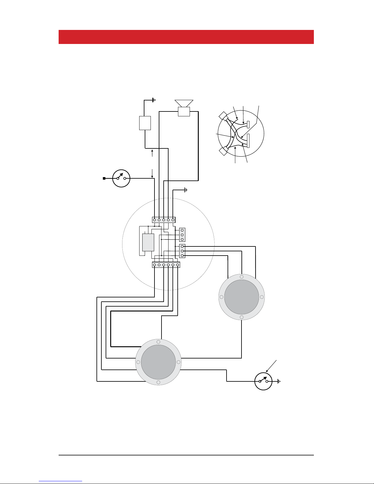
CHAPTER 4 - WIRING DIAGRAMS
N
A
C
N
I
A
E
D
D
A
A
M
BLACK
815UHP/H
HYDRAULIC TRAILER APPLICATION, ALL COMPONENTS MOUNTED ON TRAILER
WIRING DIAGRAM - ONE COMPARTMENT WITH 808P2 GAUGE, 815UHP/H SPILLSTOP AND 815JBHD JUNCTION BOX
808P2 GAUGE
BLACK
GREEN
RED
WHITE/ORANGE
(HOSE PROTECTION)
USE ONLY SWITCHES AVAILABLE
FROM GARNET TECHNOLOGIES.
NON APPROVED SWITCHES MAY
FAIL PREMATURELY.
SPILLSTOP
PROGRAM A4 IN 808P2 GAUGE
AS SHUTDOWN JUST ABOVE
A1 SHUTDOWN POINT.
(GROUND)
HOSE PRESSURE SWITCH
(+12V)
(SPILLSTOP)
(GROUND)
YELLOW
ORANGE
RED
(HORN)
(GAUGE)
(+12V POWER)
Wiring-815UHP,808P2,815JBHD Hydraulic Sw D.cdr September 16, 2015
GREEN
(SHUTDOWN)
WHITE/YELLOW
(OVER-RIDE)
+12V
REAR GAUGE
HORN
SHUTDOWN
GROUND
SHUT DOWN RELAY
NC
NO
COM
COIL
COIL
85
86
87A
30
87
HORN &
SOLENOID
CABLE
GROUND
NEG HORN
+12V PWR
+12V HORN
SEELEVEL
FRONT GAUGE
+12V
SPILLSTOP
GROUND
+12V
SPILLSTOP
815U
SPILLSTOP
CABLE
REAR
GAUGE
CABLE
FRONT
GAUGE
CABLE
SOLENOID
GROUND
HYDRAULIC JUNCTION BOX WIRING
TRAILER
GROUND
PUMP
BYPASS
VALVE
(NORMALLY OPEN)
MANDATORY
WARNING
HORN
(BACK UP ALARM)
(UNDER 1 AMP)
+12V
GND
USE ONLY 5 WIRE 14 GAUGE CABLE.
DO NOT USE 7 WIRE CABLE AS THE
WIRE GAUGE IS TOO SMALL.
MIN 14
GAUGE
WIRE
+12 VOLT SOURCE
HOBBS SWITCH CLOSED WHEN
PARKING BRAKES ARE APPLIED
OR AIR OPERATED VENT IS OPEN
TRAILER
GROUND
THIS PRESSURE SWITCH IS ACTIVATED BY HOSE PRESSURE
ON THE DISCHARGE SIDE OF THE PUMP. IT IS NORMALLY CLOSED
WHEN PRESSURE IS LOW. (SWITCH OPENS WHEN THERE IS A FAULT)
THE HOSE BURST RATING MUST EXCEED THE PRESSURE SWITCH RATING.
YELLOW
(A4)
BYPASS
BUTTON
OVER-RIDE
& MANUAL
RE-ARM
BUTTON
WHITE/YELLOW
WIRE TO 808P2
A4 ALARM
WHITE/YELLOW
WIRE FROM SMALL
CONNECTOR
WHITE WIRE
FROM LARGE
CONNECTOR
EXISTING ENCLOSURE WIRING
COMBO LEFT
BUTTON
BLACK GROUND
WIRE FROM LARGE
CONNECTOR
WHITE/BLUE
WIRE FROM SMALL
CONNECTOR
PURPLE WIRE
FROM LARGE
CONNECTOR
COMBINATION LEFT BUTTON-MANUAL RE-ARM BELOW HORN ALARM, AND OVER-RIDE ABOVE HORN ALARM
Page 11815UHP/H Manual
Wiring Guide - Main Connector
Red: +12V power
Black: Ground
Orange: Horn alarm output
Green: Shutdown alarm output
Yellow: SPILLSTOP signal from the 808P2/810PS2 gauge
Purple: (connected) Horn Bypass switch
White: (connected) Manual Re-arm switch
Wiring Guide - Sensor Connector
White/Orange: Hose protection switch
White/Blue (connected): Loading switch - always grounded
White/Yellow
(via over-ride switch):
Over-ride switch connection to A4
Grey
(may not be present):
Horn conguration - not used

Page 12 815UHP/H Manual
If problems are encountered, check the following:
1. Is the controller getting at least 8 volts?
2. Are all the wires properly connected, with no short circuits?
3. Are the 808P2 or 810PS2
SEELEVEL
gauges working properly?
4. Are the 808P2 or 810PS2 gauges programmed properly?
5. If the horn is not sounding, does the horn itself work?
To test the various components, substitute a known good
component to see if the rest of the system is working. If the pump
will not start, ground the green wire from the controller. If the
pump still does not start, the problem is in the relay or associated
wiring. If the pump now starts, and the controller indicates no
shutdown alarm (or is bypassed), then the controller is bad. If the
horn will not sound, ground the orange wire from the controller.
If the horn still does not sound, the problem is in the horn or
associated wiring. If the horn now sounds, and the controller
indicates a horn alarm that is not bypassed, then the controller is
bad.
CHAPTER 5 - TROUBLESHOOTING GUIDE

Page 13815UHP/H Manual
CHAPTER 6 - SERVICE AND WARRANTY INFORMATION
T
he warranty will only apply only if the warranty card that is shipped with the equipment
has been returned to Garnet Instruments Ltd.
DISCLAIMER OF WARRANTY ON HARDWARE
Garnet Instruments Ltd. warrants equipment manufactured by Garnet to be free from defects in
material and workmanship under normal use and service for a period of one year from the date
of sale from Garnet or an Authorized Dealer. The warranty period will start from the date of
purchase or installation as indicated on the warranty card. Under these warranties, Garnet shall
be responsible only for actual loss or damage suffered and then only to the extent of Garnet’s
invoiced price of the product. Garnet shall not be liable in any case for labor charges for indirect,
special, or consequential damages. Garnet shall not be liable in any case for the removal and/or
reinstallation of defective Garnet equipment. These warranties shall not apply to any defects or
other damages to any Garnet equipment that has been altered or tampered with by anyone other
than Garnet factory representatives. In all cases, Garnet will warrant only Garnet products which
are being used for applications acceptable to Garnet and within the technical speci cations of the
particular product. In addition, Garnet will warrant only those products which have been installed
and maintained according to Garnet factory speci cations.
LIMITATION ON WARRANTIES
These warranties are the only warranties, expressed or implied, upon which products are sold by
Garnet and Garnet makes no warranty of merchantability or tness for any particular purpose in
respect to the products sold. Garnet products or parts thereof assumed to be defective by the
purchaser within the stipulated warranty period should be returned to the seller, local distributor,
or directly to Garnet for evaluation and service. Whenever direct factory evaluation, service or
replacement is necessary, the customer must rst, by either letter or phone, obtain a Returned
Material Authorization (RMA) from Garnet Instruments directly. No material may be returned to
Garnet without an RMA number assigned to it or without proper factory authorization. Any returns
must be returned freight prepaid to: Garnet Instruments Ltd, 286 Kaska Road, Sherwood Park,
Alberta, T8A 4G7. Returned warranted items will be repaired or replaced at the discretion of Garnet
Instruments. Any Garnet items under the Garnet Warranty Policy that are deemed irreparable by
Garnet Instruments will be replaced at no charge or a credit will be issued for that item subject to
the customer’s request.
If you do have a warranty claim or if the equipment needs to be serviced, contact the installation
dealer. If you do need to contact Garnet, we can be reached as follows:
CANADA UNITED STATES
Garnet Instruments Ltd. Garnet US Inc.
286 Kaska Road 5360 Granbury Road
Sherwood Park, AB T8A 4G7 Granbury, TX 76049
CANADA USA


MAIL IN WARRANTY
MODEL NO. SERIAL NO.
DATE PURCHASED DATE INSTALLED
YR/MO/DAY YR/MO/DAY
COMPANY NAME
PRINCIPAL CONTACT
ADDRESS
TELEPHONE FAX
IN CANADA RETURN TO:
Garnet Instruments Ltd.
286 Kaska Road
Sherwood Park, AB T8A 4G7
CANADA
SENDER BAR SERIAL NO. (if applicable)
IMPORTANT: WITHOUT THE SERIAL NUMBER OF EACH UNIT IT IS
DIFFICULT TO DETERMINE WARRANTY VALIDITY
DEALERS NAME
WARRANTY CONTACT
ADDRESS
TELEPHONE FAX
IN UNITED STATES RETURN TO:
Garnet US Inc.
5360 Old Granbury Road
Granbury, TX 76049
USA
IMPORTANT: RETURNING THIS CARD WILL ENABLE US TO NOTIFY YOU IN THE EVENT OF A PRODUCT RECALL OR TO SUPPLY YOU WITH REQUIRED PRODUCT SAFETY INFORMATION.
TO MAXIMIZE YOUR WARRANTY PLEASE REGISTER ONLINE AT www.garne nstruments.com OR MAIL THIS FORM IN TO GARNET.
LIMITED WARRANTY REGISTRATION

Printed in Canada
www.garnetinstruments.com
CANADA
Garnet Instruments Ltd.
286 Kaska Road
Sherwood Park, AB T8A 4G7
USA
Garnet US Inc.
5360 Old Granbury Road
Granbury, TX 76049
P: 780-467-1010
F: 780-467-1567
TF: 1-800-617-7384
P: 817-578-8601
F: 817-573-0005
TF: 1-877-668-7813
Table of contents
Other Garnet Controllers manuals


Popular Controllers manuals by other brands

ASHAPOWER
ASHAPOWER SURYA-50 user manual

ABB
ABB ACS 800 Series Firmware manual

Spang Power Electronics
Spang Power Electronics 451-25 owner's manual

Bamo
Bamo BIR 7110 instruction manual

ABB
ABB i-bus KNX AC/S 1.x.1 Series product manual

GEORGE FISCHER
GEORGE FISCHER SIGNET 9030 Intelek-Pro instruction manual


