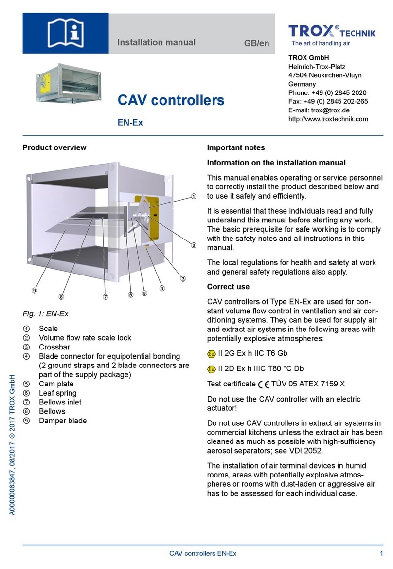
Trox VFC series User manual

1
Operating manual
TROX air terminal units
Type VFC volume ow controllers
VFC
VFC series volume ow controllers
Subject to change · All rights reserved © TROX GmbH (10/2018) · Publication no. M/VFC/EN/3
General information ________________________ 2
Correct use __________________________________2
Safety notes __________________________________2
Area of application _________________________ 2
Operating modes ______________________________2
Product description ________________________ 3
Installation ________________________________ 4
Commissioning and wiring __________________ 5
Constant volume ow rate operation _______________5
Variable volume ow rate operation, actuator
with potentiometers ____________________________6
min - max switching wiring _____________________7
Variable volume ow rate wiring___________________7
min - max switching operation, actuator
with mechanical stops __________________________8
min - max switching wiring _____________________9
min - max switching setting ___________________10
Retrotting an actuator_____________________ 11
Variable volume ow rate expansion set ___________11
min - max switching expansion set _____________12
1) Actuators for CAV controllers according to order code
VFC series volume ow controllers Expansion set
Code1) Function Actuator TROX part no. Code TROX
part no.
untill 4/2018 from 5/2018
-Constant volume ow rate - - --
E01 24 V, min- max switching, potentiometer M466EP6 A00000038358 E01 NR-VAV-E01
E02 230 VAC, min- max switching, potentiometer M466EP8 A00000038359 E02 NR-VAV-E02
E03 24 V AC/DC, variable volume ow, potentiometer,
control signal 0 to 10 V DC M466EP7 A00000038360 E03 NR-VAV-E03
M01 24 V, min- max switching, mechanical stops M466EP4 M466EP4 M01 NR-VAV-M01
M02 230 VAC, min- max switching, mechanical stops M466EP5 M466EP4 M02 NR-VAV-M02

2
Operating manual
TROX air terminal units
Type VFC volume ow controllers
VFC
Area of application
TROX VFC series volume ow controllers are mechanical
system-powered controllers for controlling the airow in
constant and variable air volume systems.
3 variants of the volume ow controllers are available:
• Constant volume ow rate
• min- max switching
Actuator with potentiometers (type E01, E02)
Actuator with mechanical stops (type M01, M02)
• Variable volume ow rate,
Actuator with potentiometers (type E03)
The set ow rate must always be set by the customer on site.
The setting is made without adjustment devices.
Each volume ow controller has a sticker with a characteristic
for determining the volume ow rate. One or two settings
are read o and transferred to the rotary knob or actuator
(potentiometer or mechanical stops).
Operating modes
• Constant volume ow rate
The volume ow controller keeps the set ow rate constant
independently of the duct pressure.
• Variable volume ow rate
The volume ow controller keeps a variable set ow rate
constant independently of the duct pressure. For this
purpose, the volume ow controller receives a control
variable from a room temperature controller or air quality
controller, a set point adjuster or a DDC outstation. The
control variable is a 0 to 10 V DC voltage signal.
• min- max switching
The volume ow controller works with two setpoint values
that are switched over using switches or relays provided by
the customer.
General information
Correct use
The volume ow controllers are suitable for use in ventilation
and air conditioning systems. Particular conditions can
restrict the functioning capacity and must be taken into
account during the design stage:
• Use of VFC series volume ow controller in aircraft is not
permitted.
• In systems with aggressive air, only air terminal units made
of plastic should be used, subject to extensive tests for
suitability.
• Galvanised sheet steel units must not be installed in
contaminated environments (e.g. acetic acid).
• The controller and actuator do not contain any parts that
can be exchanged or repaired by the user.
• The actuator contains electronic components therefore
must be separated from domestic waste. When disposed
of, local up to date regulations must be complied with.
• The mechanical components of VFC series volume ow
controllers are maintenance-free.
• Sticky constituents of the air, in particular in association
with u, can lead to impairment or failure of the regulation
function.
Safety notes
Danger!
Danger of electric shock! Do not touch any live
components! Electrical equipment carries a
dangerous electrical voltage.
• Only skilled qualified electricians are allowed to
work on the electrical system.
• Switch off the power supply before working on
any electrical equipment.
• Safety transformers must be used.
• Installation should only be carried out by specialists.
The normal rules of site working, in particular the health
and safety regulations must be complied with.
• For installation, wiring, and commissioning observe
the recognised technical regulations, especially safety
and accident prevention regulations.
• Due to the danger of injury on edges and burrs, transport
and installation may only be performed while wearing
gloves.
• Install the units prociently with suspension points
and secure with locknuts. Only load the suspension points
with the units' own weight. Adjacent components and
connecting ducts must be supported separately.
• Only use units with ATEX approval for rooms containing
a potentially explosive atmosphere.

3
Operating manual
TROX air terminal units
Type VFC volume ow controllers
VFC
For technical and acoustic data on VFC series volume
ow controllers, refer to the control units catalogue.
1Adjustment scale
Volume ow rate characteristic
Rotary knob
Actuator, volume ow rate is set on potentiometers
Actuator, volume ow rate is set with mechanical stops
E01 ... E03
M01 ... M02
• For constant air ow rate
• Volume ow rate is set on site using the rotary knob
• Factory setting 5
Actuator E01, E02, E03
• For variable airow rate or min- max switching
• Volume ow rate is set on potentiometers
• Shut-o down to leakage airow is possible (setting 0)
• Height of the actuator 85 mm
• Factory settings:
min = 4
max = 8
Actuator M01, M02
• For min- max switching
• Volume ow rate is set using mechanical stops
• Shut-o down to leakage airow is possible (setting 0)
• Flat design, height of the actuator 35 mm
min- max switching, actuator with mechanical
stops
Variable volume ow rate, actuator with
potentiometers
Constant volume ow rate
Product description
1
1
2
1
2
2
3
4
5
5
4
2
3

4
VFC
Operating manual
TROX air terminal units
Type VFC volume ow controllers
VFC
Installation
1.5 D
VFC
VFC
Manifold
Installation in a branch
Connection with ducting
Installation behind a bend
Combination with volume ow rate measuring unit
VFC
Suspension
D
min. 1 D
Connection
elements, e.g.
tube clamp with
rubber seal
Installation location and type of connection
• Select the installation location so the scale and
characteristic of the controller remain accessible.
• With reference to the characteristic, set the pointer to the
required volume ow rate.
• Horizontal or vertical controller installation.
• Note the airow direction according to the arrow on the
characteristic.
• Note for installation in front of and behind elbows, aps
or other obstacles with aerodynamic and acoustic eects.
• Horizontal or vertical installation; in combination with
volume ow rate measuring unit (VMR), arrange the sensor
tubes at 45° oset from the controller axis.
• Installation behind a bend:
Maintain a curvature radius of at least 1D unless there
is an additional straight inow length.
• Direct connection to a main duct/manifold: Maintain at least
1.5 D straight inow length
• Shorter inow lengths result in tighter tolerances.
• Direct connection to a main duct is permitted without
perforated sheet metal in extract air operation.
• Free intake not permitted, inow length 1.5 D required.
Inow nozzles are recommended in order to reduce the
pressure losses.
Connection with ducting
The connection diameters are appropriate for tubes
according to EN 1506 or EN 13180.
• No drilling work is allowed to be performed on the
controller!
• Before connecting the controllers, check the ducting
for contamination.
• Use standard TROX lip seals for connecting to the ducting.
VMR

5
Operating manual
TROX air terminal units
Type VFC volume ow controllers
VFC
Locking screw
Rotary knob
Setting the set ow rate
Each VFC carries a characteristic to determine the setting
values on site (see example, nominal size 160).
min settings below 3 results in an unregulated airow
dependent on the duct pressure that is not less than min-unit.
Constant volume ow control, volume ow rate
setting with rotary knob
Characteristic for determining the volume ow rate
Constant volume ow rate operation
Volume ow rate setting values
Nominal size
l/s m3/h
Value to be set Value to be set
345678910345678910
80 6 7 10 14 19 25 33 42 20 26 35 49 68 91 119 150
100 6 10 15 22 30 40 50 65 22 36 54 79 108 144 180 234
125 11 15 22 30 44 60 78 100 40 54 79 108 160 215 280 360
160 18 31 45 60 83 110 146 183 65 110 162 216 300 396 525 660
200 25 40 60 85 120 155 205 250 90 144 216 306 432 558 738 900
250 37 64 100 135 183 240 310 370 133 230 360 486 660 864 1116 1332
Set the set ow rate as follows:
• Determine the setting value for the set ow rate from the
characteristic or the table below.
• Unscrew the locking screw.
• Move the pointer of the rotary knob to the setting value.
• Tighten the locking screw.
Commissioning and wiring
60 100
65
5038 100 150 200 250 300 350 392
VFC 160
18 40 80 120 140 185
160 180
100 200 300 400 500 550450350250150 666600 650
3
4
5
6
7
8
9
10
l/s
cfm
m³/h

6
Operating manual
TROX air terminal units
Type VFC volume ow controllers
Actuator E01 ... E03
Setting the set ow rate
Each VFC carries a characteristic to determine the setting
values on site (see example, nominal size 160).
min values below 3 results in an unregulated airow dependent
on the duct pressure that is not less than min-unit.
Set the set ow rate as follows:
• Determine the setting value for the set ow rate from the
characteristic or the table on page 5.
• Set the values on the min- and max potentiometers.
• Factory setting:
min = 4
max = 8
• Shut-o down to leakage airow is possible, value to be set 0
Functional test
A functional test can be performed very easily using the service
button and the indicator light.
• Press service button for at least 1 second
• Actuator turns toward min
• Actuator turns toward max
• Actuator returns to control mode
Indicator light provides functional information
• Permanently on : Position set
• Flashing once a second : Actuator operating
• Flashing twice a second : Actuator is jammed and stationary
• O : No supply voltage
Actuator E03
The relationships between the setting value and output signal
U, or control signal w, are shown in the two characteristics on
the left.
The output signal does not correspond to the currently
measured volume flow rate, but reflects the setpoint value.
Example:
Factory set values:
min = 4
min = 8
Required value: 6
--> Required control signal: 5 V
Available output signal: 6 V corresponding to set value 6
max
potentiometer
Indicator light
Service button
min
potentiometer
Variable volume ow rate operation, actuator with
potentiometers
Characteristic for determining the volume ow rate
0
6
10
06 V 10 VDC
0
6
4
8
10 max
min
05V 10 VDC
Characteristic of the actual value signal
Characteristics of the control signal
Output signal U
Control signal w
Value to be set Value to be set
E03
E03
60 100
65
5038 100 150 200 250 300 350 392
VFC 160
18 40 80 120 140 185
160 180
100 200 300 400 500 550450350250150 666600 650
3
4
5
6
7
8
9
10
l/s
cfm
m³/h

7
Operating manual
TROX air terminal units
Type VFC volume ow controllers
1234
y
VFC
~~
Continuous control input signal
Variable volume ow rate wiring
E03
24 V
Room temperature
controller
Actual value
output (value to
be set)
123VFC
~S1
E01, E02
24 V / 230 VAC
12
0
3
~
VFC
2
S2
3
2-wire control min / max
24 V / 230 VAC
E01, E02
Danger!
Danger of electric shock! Do not touch any live
components! Electrical equipment carries
a dangerous electrical voltage.
• Only skilled qualified electricians are allowed
to work on the electrical system.
• Switch off the power supply before working on
any electrical equipment.
Actuator E01, E02
Electrical connection data:
E01: 24 V AC ±20% 50/60 Hz; 4 VA
24 V DC ±20% 2,5 W
E02: 230 V AC 50/60 Hz 4 VA
Switches provided by the customer (volt-free contacts) can
be used for making the switching procedures shown below:
1-wire control (illustration above)
Switch S1 open : min
Switch S1 closed : max
2-wire control (3-point) (illustration in middle)
Switch S2 at 0: Drive stopped
Switch S2 at 2: min
Switch S2 at 3: max
Actuator E03
Electrical connection data:
Supply: 24 V AC ±20% 50/60 Hz 4 VA
24 V DC ±20% 2,5 W
Control signal: 0-10 V DC Ra > 100 kohm
Actual value output: 0-10 V DC
Room temperature control
A dedicated room temperature controller or a DDC outstation
with 0-10 V DC output is connected with at least 2 wires
(terminals 1 and 3) as shown in the circuit diagram. If the
controllers are on the same supply voltage (24 V) make sure
that terminal 1 of the VFC is identical to the ground of the
control signal.
Note:
Override control max with 24 V DC at terminal 3.
1-wire control min / max
min - max switching wiring
~
- +
N L
~
- +
N L
- +
Actuator E01 ... E03

8
Operating manual
TROX air terminal units
Type VFC volume ow controllers
Mechanical stop
for min
Magnetic gear-
box disengage-
ment
Mechanical stop
for max
Position indicator
with magnet
Variable volume ow control, min and max
setting with mechanical stops
Characteristic for determining the volume ow rate
Set the set ow rate as follows:
• Determine the setting value for the set ow rate from the
characteristic or the table on page 5.
• Activate gearbox disengagement with magnet. The magnet
is integrated in the removable position indicator
• Make the corresponding settings on the mechanical stops.
• Deactivate gearbox disengagement again and reconnect the
position indicator, see also page 10.
Setting the set ow rate
Each VFC carries a characteristic to determine the setting
values on site (see example, nominal size 160).
min settings below 3 results in an unregulated airow
dependent on the duct pressure that is not less than min-unit.
U
..
min- max switching operation, actuator with
mechanical stops
Actuator M01 ... M02
60 100
65
5038 100 150 200 250 300 350 392
VFC 160
18 40 80 120 140 185
160 180
100 200 300 400 500 550450350250150 666600 650
3
4
5
6
7
8
9
10
l/s
cfm
m³/h

9
Operating manual
TROX air terminal units
Type VFC volume ow controllers
Danger!
Danger of electric shock! Do not touch any
live components! Electrical equipment carries
a dangerous electrical voltage.
• Only skilled qualified electricians are allowed
to work on the electrical system.
• Switch off the power supply before working
on any electrical equipment.
Electrical connection data:
M01: 24 V AC ±20% 50/60 Hz 1 VA
24 V DC ±20% 0,5 W
M02: 230 V AC 50/60 Hz 3 VA
Switches provided by the customer (volt-free contacts) can
be used for making the switching procedures shown below:
1-wire control (illustration above)
Switch S1 open : max
Switch S1 closed : min
2-wire control (3-point) (illustration in middle)
Switch S2 at 0: Drive stopped
Switch S2 at 2: max
Switch S2 at 3: min
123VFC
~S1
12
0
3
~
VFC
2
S2
3
M01, M02
M01, M02
1-wire control min / max
2-wire control (3-point) min / max
min- max switching wiring
24 V / 230 VAC
24 V / 230 VAC
~
- +
N L
~
- +
N L
Actuator M01 ... M02

10
Operating manual
TROX air terminal units
Type VFC volume ow controllers
Setting the mechanical stops
Magnet
magnetic gear
release
2
3
1
Remove the position indicator, there is a magnet on the
reverse
Place the magnet on the point indicated with “magnetic gear
release”. The gearbox is now disengaged and the actuator
can be moved.
min- max switching setting
Remove the mechanical limiters
Setmin or max on the rotary knob; reattach the mechanical
limiters in the corresponding positions.
Remove the position indicator with magnet and put back on
the axial holder.
4
U
..
Actuator M01 ... M02

11
Operating manual
TROX air terminal units
Type VFC volume ow controllers
VFC
Mounting bracket
Rotary knob
Actuator
Subsequent installation of actuators
The VFC version with a rotary knob can be subsequently
equipped with an actuator.
For this purpose, it is rst necessary to remove the locking
screw and move the rotary knob to position 5. The actuator is
simply pushed on, and it engages in the mounting bracket.
Order code for expansion sets, see page 1
Fixing screw
Setting 5
Mounting the actuator
Variable volume ow rate expansion set
Retrotting an actuator
Perform the following steps to mount the actuator:
• Unscrew the locking screw and remove it
• Move the rotary knob to setting 5
• Push on the actuator until the xing lugs engage
• See page 6 for setting the set ow rates
Actuator E01 ... E03

12
Operating manual
TROX air terminal units
Type VFC volume ow controllers
VFC, standard
construction
Mounting bracket
Coupling Anti-twist facility
Rotary knob
Actuator
Subsequent installation of actuators
The VFC version with a rotary knob can be subsequently
equipped with an actuator. For this purpose, it is rst
necessary to remove the locking screw and move the rotary
knob to position 5.
Order code for expansion sets, see page 1
Locking screw
Coupling
Rotary knob
1
2
Perform the following steps to mount the actuator:
• Unscrew the locking screw and remove it
• Move the rotary knob to position 5
• Engage the coupling
• Engage the anti-twist facility on the mounting bracket
Mounting the actuator
min- max switching expansion set
3• Attach the actuator, it engages in the anti-twist facility
• See page 10 for setting the set ow rates
Actuator M01 ... M02
Table of contents
Other Trox Controllers manuals
Popular Controllers manuals by other brands
PENGWYN
PENGWYN 485-1P-JS Technical manual
GESTRA
GESTRA NRR 2-40 installation instructions
Arbor Technology
Arbor Technology ARES-1980 Series user manual
Tech Controllers
Tech Controllers EU-L-12 user manual
SYCLOPE electronic
SYCLOPE electronic TERE'O Touch XL Installation and operating instructions

Blue Sky International
Blue Sky International MK II owner's manual

Mitsubishi
Mitsubishi MELDAS TRS50 manual
Delta Electronics
Delta Electronics Programmable Logic Controller DVP06XA-H2 instruction sheet
Johnson Controls
Johnson Controls S1-33103010000 installation manual

Trane
Trane Tracer ZN511 user manual
Dinstar
Dinstar SBC3000 user manual
Full Gauge Controls
Full Gauge Controls MT-531Ri plus quick start guide
