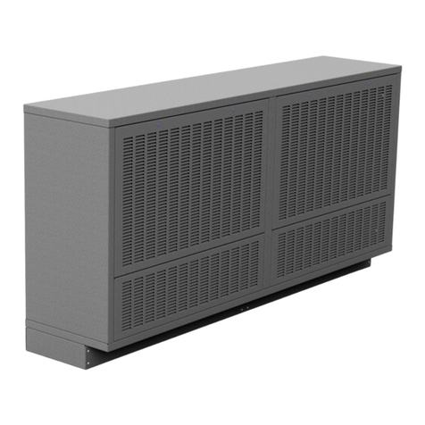
Trox DRH Series User manual

&HQWULIXJDOURRIIDQV
'5+'59'59)'59)+%9'
%9')
,QVWDOODWLRQDQGRSHUDWLQJPDQXDO
5HDGWKHLQVWUXFWLRQVSULRUWRSHUIRUPLQJDQ\WDVN
)LUHJDVFRQVWUXFWLRQWHVWHGLQDFFRUGDQFHZLWK(1
*%HQ

1925112, 1, GB/en
© 2018
TROX X-FANS GmbH
Heinz Trox Str. 1
36251 Bad Hersfeld, Germany
Telephone: +49 6621/950-0
Fax: +49 6621/950-100
email: [email protected]
Internet: www.trox-xfans.de
08/2019
Centrifugal roof fans DRH; DRV; DRVF; DRVF-H; BVD; BVD(F600)
2

1 General............................................................... 4
1.1 About this manual........................................ 4
1.2 Explanation.................................................. 4
1.3 Limitation of liability..................................... 5
1.4 Copyright..................................................... 5
1.5 Replacement parts...................................... 5
1.6 Liability for defects....................................... 5
1.7 Customer service......................................... 5
2 Safety.................................................................. 7
2.1 System owner's responsibility..................... 7
2.2 Personnel requirements.............................. 7
2.2.1 Qualifications............................................ 7
2.2.2 Unauthorised persons.............................. 8
2.3 Correct use.................................................. 8
2.4 Explosion protection.................................... 8
2.5 Personal protective equipment.................. 10
2.6 Specific hazards........................................ 11
2.7 Safeguards................................................ 12
2.8 Behaviour in the event of hazardous situa-
tions or accidents...................................... 13
2.9 Labelling.................................................... 13
3 Technical data.................................................. 15
3.1 Design versions......................................... 15
3.1.1 Type codes for roof fans......................... 15
3.1.2 Additional labelling................................. 15
3.2 Series........................................................ 15
3.2.1 Type DRH-Minivent/DRH........................ 15
3.2.2 Type DRV-Minivent/DRV........................ 15
3.2.3 Type DRVF............................................. 15
3.2.4 Type DRVF-H......................................... 16
3.2.5 BVD........................................................ 16
3.3 Connection values..................................... 16
3.4 Noise emission values............................... 16
3.5 Operating conditions................................. 17
3.5.1 Information on setting up fans that are
installed outdoors................................... 18
3.6 Operating modes....................................... 18
3.6.1 S1 continuous operation......................... 18
3.6.2 S9 speed-controlled operation............... 18
3.6.3 Smoke extract........................................ 19
3.7 Rating plate............................................... 19
4 Parts and function........................................... 21
4.1 Overview.................................................... 21
4.2 Brief description......................................... 21
4.3 Description of the sub-assembly............... 21
4.3.1 Casing.................................................... 21
4.3.2 Impeller................................................... 21
4.3.3 Fixing...................................................... 22
4.3.4 Actuator.................................................. 22
4.3.5 Additional equipment for roof fans.......... 22
5 Transport, packaging and storage................. 25
5.1 Safety notes regarding transport............... 25
5.2 Checking delivered goods......................... 25
5.3 Packaging.................................................. 25
5.4 Symbols on the packaging........................ 25
5.5 Factory settings......................................... 26
5.6 Transport................................................... 26
5.7 Storing packages....................................... 27
6 Installation and commissioning..................... 28
6.1 Safety........................................................ 28
6.2 Installation................................................. 29
6.2.1 Assembly of the fan................................ 29
6.2.2 Assembly of the flexible connector......... 31
6.3 Commissioning.......................................... 31
6.3.1 System with inductor/return smoke con-
trol dampers........................................... 31
6.3.2 Multiple fan operation............................. 31
6.3.3 Explosion-proof fans............................... 32
7 Operation.......................................................... 33
7.1 Safety........................................................ 33
7.2 Stopping in an emergency......................... 33
8 Faults................................................................ 34
8.1 Safety........................................................ 34
8.2 List of faults............................................... 36
8.3 Commissioning once a fault has been rec-
tified........................................................... 38
9 Maintenance..................................................... 39
9.1 Personnel requirements............................ 39
9.2 Safety........................................................ 39
9.3 Maintenance.............................................. 40
9.3.1 Use of monitoring systems..................... 41
9.4 Maintenance.............................................. 41
9.4.1 Lubrication.............................................. 41
9.4.2 Replacing the motor bearings................ 41
9.5 Repair........................................................ 42
9.5.1 Replacing the impeller and electric
motor...................................................... 42
9.6 Measures following maintenance work..... 42
10 Decommissioning............................................ 43
10.1 Safety...................................................... 43
10.2 Disassembly............................................ 43
10.3 Disposal................................................... 43
11 Lists of replacement parts.............................. 44
12 Index................................................................. 45
Appendix.......................................................... 47
A Commissioning report.................................. 48
B Maintenance report...................................... 50
C Tables........................................................... 53
D Installation manuals..................................... 55
Table of contents
Centrifugal roof fans DRH; DRV; DRVF; DRVF-H; BVD; BVD(F600) 3

*HQHUDO
$ERXWWKLVPDQXDO
7KLVPDQXDOHQDEOHVVDIHDQGHIILFLHQWZRUNLQJZLWKWKH
XQLW7KHPDQXDOPXVWEHNHSWQHDUWKHXQLWWREHDYDLO
DEOHIRUXVHDWDOOWLPHV,WLVHVVHQWLDOWKDWWKHVHLQGLYLG
XDOVUHDGDQGIXOO\XQGHUVWDQGWKLVPDQXDOEHIRUH
VWDUWLQJDQ\ZRUN7KHEDVLFSUHUHTXLVLWHIRUVDIH
ZRUNLQJLVWRFRPSO\ZLWKWKHVDIHW\QRWHVDQGDOO
LQVWUXFWLRQVLQWKLVPDQXDO7KHORFDOUHJXODWLRQVIRU
KHDOWKDQGVDIHW\DWZRUNDQGJHQHUDOVDIHW\UHJXODWLRQV
DOVRDSSO\,OOXVWUDWLRQVLQWKLVPDQXDODUHPDLQO\IRU
LQIRUPDWLRQDQGPD\GLIIHUIURPWKHDFWXDOXQLWGHVLJQ
,QDGGLWLRQWRWKLVPDQXDOWKHRSHUDWLQJPDQXDOVRIWKH
LQWHJUDWHGFRPSRQHQWVLQWKHDSSHQGL[DOVRDSSO\7KH
LQVWUXFWLRQVLQWKHPDQXDOV±SDUWLFXODUO\VDIHW\QRWHV±
PXVWEHREVHUYHG
([SODQDWLRQ
6DIHW\QRWHV
6\PEROVDUHXVHGLQWKLVPDQXDOWRDOHUWUHDGHUVWR
DUHDVRISRWHQWLDOKD]DUG6LJQDOZRUGVH[SUHVVWKH
GHJUHHRIWKHKD]DUG
&RPSO\ZLWKDOOVDIHW\LQVWUXFWLRQVDQGSURFHHGFDUHIXOO\
WRDYRLGDFFLGHQWVLQMXULHVDQGGDPDJHWRSURSHUW\
'$1*(5
,PPLQHQWO\KD]DUGRXVVLWXDWLRQZKLFKLIQRWDYRLGHG
ZLOOUHVXOWLQGHDWKRUVHULRXVLQMXU\
:$51,1*
3RWHQWLDOO\KD]DUGRXVVLWXDWLRQZKLFKLIQRWDYRLGHG
PD\UHVXOWLQGHDWKRUVHULRXVLQMXU\
&$87,21
3RWHQWLDOO\KD]DUGRXVVLWXDWLRQZKLFKLIQRWDYRLGHG
PD\UHVXOWLQPLQRURUPRGHUDWHLQMXU\
(;3/26,21+$=$5'
)DLOXUHWRFRPSO\ZLWKWKHVHQRWHVOHDGVWRORVVRI
H[SORVLRQSURWHFWLRQDQGPD\UHVXOWLQVHULRXVLQMXU\
DQGGHDWK
127,&(
3RWHQWLDOO\KD]DUGRXVVLWXDWLRQZKLFKLIQRWDYRLGHG
PD\UHVXOWLQSURSHUW\GDPDJH
(19,5210(17
(QYLURQPHQWDOSROOXWLRQKD]DUG
7LSVDQGUHFRPPHQGDWLRQV
8VHIXOWLSVDQGUHFRPPHQGDWLRQVDVZHOODVLQIRUPD
WLRQIRUHIILFLHQWDQGIDXOWIUHHRSHUDWLRQ
*HQHUDO
([SODQDWLRQ
&HQWULIXJDOURRIIDQV'5+'59'59)'59)+%9'%9')

6SHFLILFVDIHW\QRWHV
7KHIROORZLQJV\PEROVDUHXVHGLQVDIHW\QRWHVWRDOHUW
\RXWRVSHFLILFKD]DUGV
:DUQLQJVLJQV 7\SHRIGDQJHU
:DUQLQJGDQJHURI
FUXVKLQJ
:DUQLQJ±KLJKYROWDJH
:DUQLQJ±VXVSHQGHG
ORDG
:DUQLQJ±GDQJHU]RQH
2WKHUPDUNHUV
7KHIROORZLQJPDUNHUVDUHXVHGWRKLJKOLJKWLQVWUXFWLRQV
UHVXOWVOLVWVUHIHUHQFHVDQGRWKHUHOHPHQWVLQWKLV
PDQXDO
0DUNHU ([SODQDWLRQ
6WHSE\VWHSLQVWUXFWLRQV
Ö5HVXOWVRIDFWLRQV
5HIHUHQFHVWRVHFWLRQVLQWKLV
PDQXDODQGWRRWKHUDSSOLFDEOH
GRFXPHQWV
/LVWVZLWKRXWDGHILQHGVHTXHQFH
>3XVKEXWWRQ@ &RQWUROHOHPHQWVHJSXVKEXWWRQV
VZLWFKHVRUGLVSOD\HOHPHQWVHJ
/('V
µ'LVSOD\¶ 6FUHHQHOHPHQWVHJEXWWRQVRU
PHQXV
/LPLWDWLRQRIOLDELOLW\
7KHLQIRUPDWLRQLQWKLVPDQXDOKDVEHHQFRPSLOHGZLWK
UHIHUHQFHWRWKHDSSOLFDEOHVWDQGDUGVDQGJXLGHOLQHV
WKHVWDWHRIWKHDUWDQGRXUH[SHUWLVHDQGH[SHULHQFHRI
PDQ\\HDUV
7KHPDQXIDFWXUHUGRHVQRWDFFHSWDQ\OLDELOLW\IRUGDP
DJHVUHVXOWLQJIURP
1RQFRPSOLDQFHZLWKWKLVPDQXDO
,QFRUUHFWXVH
2SHUDWLRQRUKDQGOLQJE\XQWUDLQHGLQGLYLGXDOV
8QDXWKRULVHGPRGLILFDWLRQV
7HFKQLFDOFKDQJHV
8VHRIQRQDSSURYHGUHSODFHPHQWSDUWV
3OHDVHREVHUYHRXUFRPPLVVLRQLQJDQGPDLQWHQDQFH
LQVWUXFWLRQVLQ&KDSWHUV
ª
µ,QVWDOODWLRQDQGFRP
PLVVLRQLQJ¶RQSDJHDQG
ª
µ0DLQWHQDQFH
RQSDJH
7KHDFWXDOVFRSHRIGHOLYHU\PD\GLIIHUIURPWKHH[SODQ
DWLRQVDQGLOOXVWUDWLRQVSURYLGHGLQWKLVPDQXDOIRUVSH
FLDOYHUVLRQVWKHXVHRIDGGLWLRQDORUGHURSWLRQVRUDVD
UHVXOWRIUHFHQWWHFKQLFDOFKDQJHV7KHREOLJDWLRQV
DJUHHGLQWKHRUGHUWKHJHQHUDOWHUPVDQGFRQGLWLRQV
WKHPDQXIDFWXUHUVWHUPVRIGHOLYHU\DQGWKHOHJDOUHJX
ODWLRQVLQHIIHFWDWWKHWLPHWKHFRQWUDFWLVVLJQHGVKDOO
DSSO\:HUHVHUYHWKHULJKWWRPDNHWHFKQLFDOFKDQJHV
&RS\ULJKW
7KLVPDQXDOLVSURWHFWHGE\FRS\ULJKWDQGLVH[FOXVLYHO\
IRUXVHLQ\RXUFRPSDQ\E\DXWKRULVHGSHUVRQQHO9LROD
WRUVZLOOEHKHOGOLDEOHIRUDQ\GDPDJH7KHULJKWWRIXU
WKHUFODLPVUHPDLQVUHVHUYHG
5HSODFHPHQWSDUWV
:$51,1*
6DIHW\ULVNFDXVHGE\LQFRUUHFWUHSODFHPHQW
SDUWV
&RXQWHUIHLWRUIDXOW\UHSODFHPHQWSDUWVPD\DIIHFW
VDIHW\DQGFDXVHGDPDJHPDOIXQFWLRQVRUWRWDO
IDLOXUH
7KHUHIRUH
± 2QO\XVHRULJLQDOUHSODFHPHQWSDUWVSURYLGHGE\
WKHPDQXIDFWXUHU
%X\UHSODFHPHQWSDUWVIURPDQDXWKRULVHGVXSSOLHURU
IURPWKHPDQXIDFWXUHU6HHDGGUHVVRQSDJH
7KHOLVWVRIUHSODFHPHQWSDUWVFDQEHIRXQGLQ&KDSWHU
ª
µ/LVWVRIUHSODFHPHQWSDUWV¶RQSDJH
/LDELOLW\IRUGHIHFWV
7KHSURYLVLRQVRQOLDELOLW\IRUGHIHFWVDUHGHVFULEHGLQ
3RLQW9,RIWKH*HQHUDO7HUPVRI'HOLYHU\DQG3D\PHQW
7KHSURYLVLRQVFDQEHYLHZHGRQRXUZHEVLWHDW
ZZZWUR[[IDQVGHXQGHU³'HOLYHU\DQGSD\PHQWWHUPV´
&XVWRPHUVHUYLFH
2XUFXVWRPHUVHUYLFHWHDPLVDYDLODEOHWRSURYLGHDQ\
WHFKQLFDOLQIRUPDWLRQ,QIRUPDWLRQDERXWWKHUHVSRQVLEOH
FRQWDFWSHUVRQLVDOZD\VDFFHVVLEOHRYHUWKHSKRQHE\
ID[E\HPDLORURYHUWKH,QWHUQHWVHHWKHPDQXIDFWXU
HU¶VDGGUHVVRQSDJH:HRIIHUWKHIROORZLQJVHUYLFHV
*HQHUDO
&XVWRPHUVHUYLFH
&HQWULIXJDOURRIIDQV'5+'59'59)'59)+%9'%9')

Assembly, commissioning and maintenance of the
fans
Measurement, analysis and evaluation of all the
data required for operation (e.g.: pressure, volume,
sound, vibrations)
Operational balancing
Replacement parts service
Individual advice and help placing orders
General
Customer service
Centrifugal roof fans DRH; DRV; DRVF; DRVF-H; BVD; BVD(F600)6

2 Safety
This section provides an overview of all the important
safety issues for the best possible protection of per-
sonnel as well as for safe and fault-free operation.
Failure to comply with the instructions and safety notes
listed in this manual can lead to serious hazards.
2.1 System owner's responsibility
The unit is intended for commercial use. The system
owner is therefore subject to the legal obligations of
occupational health and safety regulations. In addition
to the safety notes in this manual, the applicable regula-
tions for safety, accident prevention and environmental
protection must also be complied with. In particular:
The system owner must be aware of the applicable
occupational health and safety regulations and carry
out a risk assessment to determine any additional
hazards that may exist or result from the specific
working conditions at the installation location of the
unit. The system owner has to create operating
instructions for the unit that reflect the results of this
risk assessment.
The system owner must ensure, throughout the
unit’s entire operating period, that the operating
instructions they create comply with the applicable
standards and guidelines and must adapt them as
required.
The system owner must clearly regulate and define
the responsibilities for assembly / installation, opera-
tion, maintenance and cleaning.
The system owner has to ensure that all individuals
who handle or use the unit have read and under-
stood this manual.
The system owner must regularly provide training
for the personnel and inform them of any dangers.
The system owner must provide the employees with
the required personal protective equipment.
The system owner is also responsible for ensuring that
the unit is always in a technically perfect condition. The
following therefore applies:
The system owner must ensure that the mainte-
nance intervals specified in this manual are
observed.
The system owner must have all safeguards tested
regularly to ensure that they are functional and com-
plete.
2.2 Personnel requirements
2.2.1 Qualifications
WARNING!
Danger of injury due to insufficiently qualified
individuals!
Incorrect use may cause considerable injury or
damage to property.
Therefore:
– Only specialist personnel must carry out work.
The following degrees of qualification are required for
the work described in the operating manual:
Instructed person
The instructed person has been instructed by the
system owner with regard to the tasks delegated to
them and potential hazards in the event of inappropriate
behaviour.
Skilled qualified electrician
Skilled qualified electricians are individuals who have
sufficient professional or technical training, knowledge
and actual experience to enable them to work on elec-
trical systems, understand any potential hazards related
to the work under consideration, and recognise and
avoid any risks involved.
The qualified electrician is trained especially for the field
in which they work and is familiar with the relevant
standards and regulations.
Specialist personnel
Specialist personnel are individuals who have sufficient
professional or technical training, knowledge and actual
experience to enable them to carry out their assigned
duties, understand any potential hazards related to the
work under consideration, and recognise and avoid any
risks involved.
Only persons who can be expected to perform their
work reliably are acceptable as personnel. Individuals
whose reaction time is delayed due to alcohol, drugs or
other medication must not carry out any work.
The age-specific and occupational regulations appli-
cable at the operation site must be observed when
appointing personnel.
Safety
Personnel requirements > Qualifications
Centrifugal roof fans DRH; DRV; DRVF; DRVF-H; BVD; BVD(F600) 7

2.2.2 Unauthorised persons
WARNING!
Danger for unauthorised persons!
Unauthorised persons who do not fulfil the require-
ments specified here are usually not aware of the
dangers in the work area.
Therefore:
– Keep unauthorised persons away from the work
area.
– Instruct these persons to leave the hazardous
area or work area.
– Stop work while unauthorised persons are
present in the work area.
2.3 Correct use
The unit is only designed and constructed for the
intended use described here.
The ventilation fan is only designed to convey
normal, dust-free and conditioned air, and other
non-aggressive, non-explosive gases.
The smoke exhaust fan is also designed to
convey fire gases in accordance with its tempera-
ture and time specifications.
Replace fan after use in the event of a fire!
The explosion-proof fan is designed to convey
explosive media and/or for installation in poten-
tially explosive atmospheres according to its
labelling.
Other intended uses approved by the manufacturer and
derived from the optional fan equipment are detailed in
the customer specifications.
WARNING!
Danger due to incorrect use!
Any use that extends beyond the correct use and/or
different use of the unit can lead to hazardous situa-
tions.
Therefore:
– Only use the unit for its correct use.
– Strictly comply with all of the information in this
operating manual.
Claims of any type for damages resulting from incorrect
use will not be accepted.
The system owner is solely responsible for all damages
resulting from incorrect use.
2.4 Explosion protection
ATEX Product Directive 2014/34/EU (ATEX 95)
The aim of the Directive is to protect individuals who
work in potentially explosive atmospheres. The Directive
contains the essential health and safety requirements
that the manufacturer must observe and that must be
verified by means of appropriate conformity assess-
ments. Since 30 June 2003, only units, components and
protective systems which comply with the ATEX Product
Directive 2014/34/EU can be used.
The deliverable version options are highlighted below:
Equipment groups
Equipment
group
For use in....
I Units for use in mining
II Units for use in the other areas
Classification
Zone Category EPL Safety
0 1 Ga Very high level of
safety
1 2 Gb High level of safety
2 3 Gc Normal operation
Atmosphere
G = Gases
D = Dusts
Explosion group (gas group)
Gases and vapours are split into three explosion groups
(IIA, IIB and IIC) based on their particular flammability.
The danger increases from explosion group IIA to IIC.
(The higher explosion group includes the lower ones.)
Safety
Explosion protection
Centrifugal roof fans DRH; DRV; DRVF; DRVF-H; BVD; BVD(F600)8

7HPSHUDWXUHFODVV
6L[WHPSHUDWXUHFODVVHV7WR7KDYHEHHQGHILQHGIRUWKHSHUPLVVLEOHVXUIDFHWHPSHUDWXUHV&HUWDLQFRPEXVWLEOH
JDVHVDQGYDSRXUVFDQEHDVVLJQHGWRWKHVHWHPSHUDWXUHFODVVHVEDVHGRQWKHUHOHYDQWLJQLWLRQWHPSHUDWXUHV
7KHIROORZLQJWDEOHSURYLGHVDQRYHUYLHZRIWKHPD[LPXPSHUPLVVLEOHVXUIDFHWHPSHUDWXUHVRQWKHXQLWVDQGVRPH
DVVRFLDWHGJDVHVWKDWDSSO\WRWKHWHPSHUDWXUHFODVVHV
*URXS
7HPSHUDWXUHFODVVVXUIDFHWHPSHUDWXUH
7
&
7
&
7
&
7
&
7
&
7
&
, 0HWKDQH
,,$ $PPRQLD
PHWKDQRO
QEXW\ODOFRKRO
QEXWDQH
%HQ]LQH
GLHVHO
KHDWLQJRLO
$FHWDOGHK\GH
,,% 7RZQJDV (WK\OHQH
DOFRKROHOWK\
OHQH
(WK\OHWKHU
,,& +\GURJHQ $FHW\OHQH &DUERQGLVXO
SKLGH
&RUUHFWXVH
)DQVGHVLJQDWHGDV³H[SORVLRQSURRI´DUHVXEMHFWWRWKH
OHJDOUHTXLUHPHQWVLQIRUFHZLWKUHJDUGWRWKH([SORVLRQ
3URWHFWLRQ5HJXODWLRQDQG'LUHFWLYH(87KH\
DUHSDUWRIHTXLSPHQWJURXS,,DQGDUHVXLWDEOHIRUFRQ
YH\LQJFODVV,,$DQG,,%JDVHVIURP]RQHVDQG7KH
IDQVDUHDOVRVXLWDEOHIRULQVWDOODWLRQLQDQH[SORVLYH
DWPRVSKHUHLQWKHDERYHPHQWLRQHG]RQHV
0DUNHU
,QDFFRUGDQFHZLWK'LUHFWLYH(8±NQRZQDV
$7(;±RQO\XQLWVWKDWFRQIRUPWRWKLV'LUHFWLYHFDQ
EHXVHGLQSRWHQWLDOO\H[SORVLYHDWPRVSKHUHVVLQFH
-XO\
7KHIDQVDUHVXLWDEOHIRUFRQYH\LQJSRWHQWLDOO\H[SORVLYH
PHGLDDQGRUIRULQVWDOODWLRQLQURRPVZLWKSRWHQWLDOO\
H[SORVLYHPHGLD
6SHFLDOSURYLVLRQVDFFRUGLQJWR
ª
µ&RPPLVVLRQLQJ
UHSRUW¶RQSDJHDQG
ª
µ0DLQWHQDQFHUHSRUW
RQSDJHPXVWEHREVHUYHGGXULQJFRPPLVVLRQLQJ
DQGPDLQWHQDQFH
(;3/26,21+$=$5'
8QLWFRPSRQHQWVWKDWFRPSO\ZLWK'LUHFWLYH
(8LQFOXGHDGGLWLRQDOLQIRUPDWLRQRQWKH
UDWLQJSODWH
)LJ0DUNLQJDFFRUGLQJWR$7(;
&(PDUN
8QLWLVFHUWLILHGIRU([DUHD
,, (TXLSPHQWJURXSQRWIRUXVHLQPLQLQJ
* 8QLWFDWHJRU\DQGDWPRVSKHUH
K 7\SHRISURWHFWLRQQRQHOHFWULFDO
,,% *DVJURXS
7 7HPSHUDWXUHFODVV
*E (3/HTXLSPHQWSURWHFWLRQOHYHO
2SHUDWLQJFRQGLWLRQV
:$51,1*
7KHLQOHWWHPSHUDWXUHRIWKHIORZPHGLXPPXVWEH
EHWZHHQ&DQG&7KHPDQXIDFWXUHUPXVW
EHFRQVXOWHGLIKLJKHUWHPSHUDWXUHVDUHUHTXLUHG
:$51,1*
7KHPD[LPXPRSHUDWLQJVSHHGVSHFLILHGRQWKHIDQ
UDWLQJSODWHPXVWEHREVHUYHG
6DIHW\
([SORVLRQSURWHFWLRQ
&HQWULIXJDOURRIIDQV'5+'59'59)'59)+%9'%9')

9LEUDWLRQPRQLWRULQJ
,WLVUHFRPPHQGHGWKDWWKHV\VWHPRZQHULQVWDOOD
SHUPDQHQWYLEUDWLRQPRQLWRULQJV\VWHPWRSUHYHQW
VSDUNVIURPEHLQJJHQHUDWHGDVDUHVXOWRIWKH
LPSHOOHUVWULNLQJDJDLQVWSDUWVRIWKHFDVLQJIROORZLQJ
LPEDODQFHGXULQJRSHUDWLRQ$SHUPDQHQWYLEUDWLRQ
PRQLWRULQJV\VWHPLVREOLJDWRU\LIPLVWRUGXVWLV
EHLQJFRQYH\HG
(;3/26,21+$=$5'
,JQLWLRQVRXUFHVVXFKDVVSDUNVQDNHGIODPHVDQG
KRWVXUIDFHVFDQOHDGWRH[SORVLRQVLQSRWHQWLDOO\
H[SORVLYHDWPRVSKHUHV7KHIROORZLQJWKHUHIRUH
DSSOLHVWRDOOZRUNRQXQLWVLQWKH([DUHD
±*HWZULWWHQSHUPLVVLRQEHIRUH\RXVWDUWWKHZRUN
±2QO\SHUIRUPZRUNLIWKHUHDUHQRGXVWGHSRVLWV
RUDSRWHQWLDOO\H[SORVLYHDWPRVSKHUH
±8VHRQO\WRROVWKDWKDYHEHHQDSSURYHGIRUXVH
LQDUHDVZLWKSRWHQWLDOO\H[SORVLYHDWPRVSKHUHV
$GGLWLRQDOO\
±,WPXVWEHHQVXUHGWKDWVXIILFLHQWFRROLQJDLULV
VXSSOLHGWRWKHIDQGULYHPRWRUDWDOOWLPHV
±0RWRUVZLWKDFRYHUPXVWEHXVHGLIIDQVZLWKD
YHUWLFDOPRWRUVKDIWDUHLQVWDOOHG
±6HUYLFLQJDQGPDLQWHQDQFHZRUNRQH[SORVLRQ
SURRIIDQVPXVWRQO\EHFDUULHGRXWE\TXDOLILHG
SHUVRQQHOZLWKWKHUHOHYDQWH[SORVLRQSURWHFWLRQ
TXDOLILFDWLRQVXVLQJRULJLQDOUHSODFHPHQWSDUWV
)DLOXUHWRFRPSO\ZLWKWKHVHQRWHVOHDGVWRORVVRI
H[SORVLRQSURWHFWLRQDQGPD\UHVXOWLQVHULRXVLQMXU\
DQGGHDWK
(;3/26,21+$=$5'
,IDFRPSRQHQWRUGHYLFHLVWREHLQVWDOOHGLQD
V\VWHPLQWHQGHGIRUXVHLQSRWHQWLDOO\H[SORVLYH
DWPRVSKHUHVDFFRUGLQJWR(8WKHV\VWHP
RZQHUKDVWRHQVXUHFRPSOLDQFHRIWKHHQWLUHV\VWHP
ZLWKWKDWGLUHFWLYH1RQFRPSOLDQFHPD\OHDGWRDQ
H[SORVLRQ
3HUVRQDOSURWHFWLYHHTXLSPHQW
3HUVRQDOSURWHFWLYHHTXLSPHQWPXVWEHZRUQIRUDQ\
ZRUNLQRUGHUWRUHGXFHKHDOWKRUVDIHW\KD]DUGVWRWKH
PLQLPXP
:HDUWKHSURWHFWLYHHTXLSPHQWQHFHVVDU\IRUWKH
UHVSHFWLYHZRUNIRUDVORQJDVWKHZRUNWDNHV
2EVHUYHLQVWUXFWLRQVUHODWLQJWRSHUVRQDOSURWHFWLYH
HTXLSPHQWWKDWDUHGLVSOD\HGLQWKHZRUNDUHD
6SHFLDOSURWHFWLYHHTXLSPHQWLVUHTXLUHGZKHQFDUU\LQJ
RXWVSHFLILFZRUN7KLVLVUHIHUUHGWRVHSDUDWHO\LQWKH
LQGLYLGXDOFKDSWHUVRIWKLVPDQXDO
+HDULQJSURWHFWLRQ
7RSUHYHQWKHDULQJGDPDJH
3URWHFWLYHFORWKLQJ
LVFORVHILWWLQJZLWKORZWHDUUHVLVWDQFHFORVHILWWLQJ
VOHHYHVDQGQRSURMHFWLQJSDUWV,WSUHYHQWVHQWDQJOH
PHQWLQPRYLQJPDFKLQHU\'RQRWZHDUULQJVFKDLQVRU
DQ\RWKHUMHZHOOHU\
3URWHFWLYHJORYHV
3URWHFWLYHJORYHVDUHXVHGWRSURWHFWKDQGVIURPIULF
WLRQDEUDVLRQVSXQFWXUHVGHHSFXWVDQGGLUHFWFRQWDFW
ZLWKKRWVXUIDFHV
6DIHW\KHOPHW
IRUSURWHFWLRQIURPIDOOLQJDQGIO\LQJSDUWVDQGPDWHULDOV
6DIHW\VKRHV
IRUSURWHFWLRQIURPKHDY\IDOOLQJSDUWVDQGIURPVOLSSLQJ
RQVOLSSHU\VXUIDFHV
6DIHW\
3HUVRQDOSURWHFWLYHHTXLSPHQW
&HQWULIXJDOURRIIDQV'5+'59'59)'59)+%9'%9')

2.6 Specific hazards
Electric current
DANGER!
Danger of death due to electric current!
Danger of electric shock! Do not touch any live com-
ponents! Damaged insulation or damaged parts are
a life threatening hazard.
– Have work on the electrical system carried out
only by skilled qualified electricians.
– If the insulation is damaged, disconnect the
power supply immediately and have the insula-
tion repaired.
– Before you start working on electric systems and
equipment, switch off the supply voltage and
secure it against being switched on accidentally.
Comply with the 5 safety rules:
– Disconnect.
– Secure it against being switched on acciden-
tally.
– Ensure that no voltage is present.
– Connect to the earth; short circuit connection.
– Either cover nearby parts that carry a voltage
or install barriers.
– Do not bypass or disable any circuit breakers. Be
sure to maintain the correct current rating when
you replace a circuit breaker.
– Ensure that live parts do not come into contact
with moisture. Moisture can cause a short circuit.
Noise
WARNING!
Hearing damage due to noise!
The noise level in the work area can cause severe
hearing damage.
– Always wear hearing protection while working.
– Only remain in the hazardous area if absolutely
necessary.
Moving components
WARNING!
Risk of injury due to moving components!
Moving components can cause serious injuries.
– Do not reach into or handle moving components
during operation.
– Never open covers during operation.
– The fan does not stop immediately! Check that
no components are moving before you open the
covers.
–Wear tight-fitting clothing with low tear resistance
in the hazardous area.
Rotating parts
WARNING!
Risk of injury from rotating parts!
Rotating parts in the fan can cause serious injuries.
– Do not reach into or handle the moving impeller
wheel during operation.
– Do not open covers and maintenance covers
during operation.
– Ensure that the impeller wheel is not accessible
during operation.
–The fan does not stop immediately! Ensure that
none of the components are still moving before
opening the covers for maintenance purposes.
– Switch off the unit and secure it against being
switched back on again before starting any work
on moving fan components. Wait until all parts
have come to a standstill.
Vibrations
WARNING!
Risk of injury due to strong vibrations!
Strong vibrations can result in serious injury and
chronic health impairments in the long term. The
source of the vibration can be decoupled from the
surrounding area using a vibration damper.
–Do not deactivate the vibration damper.
– Do not remain in the vibrating area during opera-
tion.
Safety
Specific hazards
Centrifugal roof fans DRH; DRV; DRVF; DRVF-H; BVD; BVD(F600) 11

6XVSHQGHGORDGV
'$1*(5
'DQJHURIGHDWKGXHWRVXVSHQGHGORDGV
)DOOLQJORDGVPD\FDXVHVHULRXVLQMXU\RUGHDWK
7KHUHIRUH
± 1HYHUZDONXQGHUVXVSHQGHGORDGV
± 2QO\PRYHORDGVXQGHUVXSHUYLVLRQ
± 2EVHUYHWKHVSHFLILFDWLRQVIRUWKHLQWHQGHG
ODVKLQJSRLQWV
± 'RQRWDWWDFKWKHOLIWLQJJHDUWRSURWUXGLQJ
PDFKLQHSDUWVRUOXJVRQDWWDFKHGFRPSRQHQWV
± (QVXUHWKDWWKHOLIWLQJJHDULVVHFXUH
± 2QO\XVHDSSURYHGKRLVWLQJGHYLFHVDQGOLIWLQJ
JHDUZLWKZLWKVXIILFLHQWORDGEHDULQJFDSDFLW\
± 'RQRWXVHDQ\IUD\HGRUZRUQURSHVDQGEHOWV
± 'RQRWSODFHURSHVRUEHOWVQHDUVKDUSHGJHVRU
FRUQHUVGRQRWNQRWRUWZLVW
± 3ODFHWKHORDGRQWKHJURXQGEHIRUHOHDYLQJWKH
ZRUNSODFH
)DOOLQJPDWHULDOV
:$51,1*
5LVNRILQMXU\GXHWRIDOOLQJPDWHULDOV
'XULQJRSHUDWLRQPDWHULDOFDQIDOOLQDQXQFRQWUROOHG
PDQQHURUEHHMHFWHGDQGFDXVHVHULRXVLQMXULHV
± 'RQRWHQWHUWKHKD]DUGRXVDUHDVGXULQJQRUPDO
RSHUDWLRQ
± :HDUDQLQGXVWULDOVDIHW\KHOPHWVDIHW\VKRHV
DQGSURWHFWLYHFORWKLQJZKHQHQWHULQJWKHKD]
DUGRXVDUHDHJGXULQJVHWWLQJPRGH
6DIHJXDUGV
:$51,1*
5LVNWROLIHIURPGHIHFWLYHVDIHJXDUGV
6DIHW\LVRQO\DVVXUHGLIWKHVDIHJXDUGVDUHLQWDFW
7KHUHIRUH
± %HIRUHVWDUWLQJZRUNFKHFNZKHWKHUWKHVDIH
JXDUGVDUHIXOO\IXQFWLRQDODQGLQVWDOOHGFRUUHFWO\
± 1HYHUGHDFWLYDWHVDIHJXDUGV
± (QVXUHWKDWVDIHJXDUGVVXFKDVWKHHPHUJHQF\
VWRSSXVKEXWWRQWULSFRUGVHWFDUHDFFHVVLEOH
DWDOOWLPHV
,03257$17
)RUIXUWKHULQIRUPDWLRQRQWKHSRVLWLRQRIWKHVDIH
JXDUGVVHH&KDSWHU
ª
µ3DUWVDQGIXQFWLRQ
RQSDJH
,VRODWRURSWLRQDO
)LJ,VRODWRU
6RPHIDQVDUHHTXLSSHGZLWKDQLVRODWRU
:$51,1*
'DQJHURIGHDWKGXHWRXQFRQWUROOHGUHDFWLYDWLRQ
8QFRQWUROOHGUHDFWLYDWLRQFDQOHDGWRVHULRXVSHU
VRQDOLQMXU\RUGHDWK
7KHUHIRUH
± %HIRUHUHDFWLYDWLRQHQVXUHWKDWDOORIWKHVDIH
JXDUGVDUHDVVHPEOHGDQGIXOO\IXQFWLRQDO
± (QVXUHWKDWQRERG\LVLQWKHKD]DUGRXVDUHD
6HFXUHGLVRODWRU
6DIHW\
6DIHJXDUGV
&HQWULIXJDOURRIIDQV'5+'59'59)'59)+%9'%9')

Fig. 3: Secured isolator
The isolator can be locked in the “0” position with a pad-
lock to prevent reactivation.
Additional smoke exhaust fan option
The isolator can also be locked in the “1” position with a
padlock to prevent deactivation in order to guarantee
the smoke extract function.
DANGER!
Danger of death due to impermissible activation
and deactivation!
Individuals can enter the hazardous area if the iso-
lator has been locked with a padlock to prevent acti-
vation. Activation could cause life-threatening injuries
to these individuals.
If the fan has been secured with a padlock to prevent
it from being deactivated, it can be equipped with an
automatic start-up feature in the event of a fire.
Deactivation ensures that the fan is not ready for
operation in the event of a fire and cannot transport
fire gases.
Therefore:
– Never remove the padlock without authorisation.
– Before removing the padlock, ensure that there
are no more individuals in the hazardous area.
Integration in an emergency stop concept required
The unit is designed for use within a system. It does not
have its own control and there is no autonomous emer-
gency stop function.
Before the unit is unit started up, install emergency stop
equipment for the unit and connect it to the system con-
trol’s safety chain.
This does not apply to smoke exhaust fans.
Connect the emergency stop equipment in such a way
that any hazardous situations for individuals and prop-
erty are excluded in the event of the power supply being
interrupted or the power supply being activated fol-
lowing an interruption.
The emergency stop equipment must be freely acces-
sible at all times.
2.8 Behaviour in the event of haz-
ardous situations or accidents
Preventative measures
Always be prepared for accidents or fire!
Keep first aid equipment (first aid kit, blankets, etc.)
and fire extinguishers close at hand.
Familiarise personnel with accident reporting, first
aid and rescue equipment.
Keep access paths for rescue vehicles clear.
Measures in the event of accidents
Trigger an emergency stop immediately, and put the
isolator into the “0” position if necessary.
Implement first aid measures.
Rescue individuals from the hazardous area.
Inform the responsible person at the operation site.
Notify the emergency services.
Clear access paths for rescue vehicles.
2.9 Labelling
The following symbols and signs are usually found in
the work area. They apply to the very location where
they are found.
WARNING!
Risk of injury due to illegible symbols!
Over time, stickers and signs can become dirty or
otherwise illegible.
Therefore:
– Ensure that all of the safety, warning and oper-
ating information is clearly legible.
– Replace illegible signs or stickers immediately.
Safety
Labelling
Centrifugal roof fans DRH; DRV; DRVF; DRVF-H; BVD; BVD(F600) 13

7HFKQLFDOGDWD
'HVLJQYHUVLRQV
,03257$17
7KURXJKWKHVHOHFWLRQRIWKHFRQVWUXFWLRQVW\OHHDFK
URRIIDQRIWKHW\SHV'5DQG%9LVDGMXVWHGWRWKH
UHTXLUHPHQWVDWWKHRSHUDWLRQVLWH$GGLWLRQDORSWLRQV
DYDLODEOHXSRQUHTXHVW
7\SHFRGHVIRUURRIIDQV
7KHW\SHFRGHLVDGLVWLQFWLYHDQGXQLTXHSURGXFWGHVLJ
QDWLRQ$OORIWKHWHFKQLFDOGDWDRIWKHSURGXFWLQWKH
752;;ϣ)$16FDWDORJXHRUSURGXFWFRQILJXUDWRUFDQEH
DFFHVVHGZLWKWKLVFRGH
)LJ7\SHFRGHBURRIIDQ
%9 %9 VPRNHH[KDXVWIDQILUHJDV
+9 9 YHUWLFDOGLVFKDUJH+ KRUL]RQWDOGLVFKDUJH
'5 FHQWULIXJDOURRIIDQQRWUHTXLUHGIRUILUHJDV
) 6WDQGDUGPRWRURXWVLGHWKHDLUIORZUHTXLUHGIRU
ILUHJDV
+. . SODVWLFIDQ+ DGGLWLRQDOPRWRUYHQWLODWLRQ
V\VWHPIRUKLJKHUFRQYH\LQJWHPSHUDWXUHVQRW
UHTXLUHGIRUILUHJDV
)DQVL]H
%ODGHH[LWDQJOH
6'9 $GGLWLRQDOHTXLSPHQW6', LQWHJUDWHGRXWOHW
VRXQGDWWHQXDWRU6'9 YHUWLFDORXWOHWVRXQG
DWWHQXDWRU6'+ KRUL]RQWDORXWOHWVRXQGDWWHQX
DWRU
$GGLWLRQDOODEHOOLQJ
7KHWHPSHUDWXUHFODVVLILFDWLRQRIVPRNHH[KDXVWIDQV
%9LVEDVHGRQ(1
) WHPSHUDWXUHRI&PLQLPXPRSHUDWLQJ
WLPHRIPLQXWHV
) WHPSHUDWXUHRI&PLQLPXPRSHUDWLQJ
WLPHRIPLQXWHV
) WHPSHUDWXUHRI&PLQLPXPRSHUDWLQJ
WLPHRIPLQXWHV
) WHPSHUDWXUHRI&PLQLPXPRSHUDWLQJ
WLPHRIPLQXWHV
) WHPSHUDWXUHRI&
6HULHV
7\SH'5+0LQLYHQW'5+
)LJ7\SH'5+0LQLYHQW'5+
7\SH'590LQLYHQW'59
)LJ7\SH'590LQLYHQW'59
7\SH'59)
)LJ7\SH'59)
7HFKQLFDOGDWD
6HULHV!7\SH'59)
&HQWULIXJDOURRIIDQV'5+'59'59)'59)+%9'%9')

3.2.4 Type DRVF-H
Fig. 9: Type DRVF-H
3.2.5 BVD
3.2.5.1 BVD F400
Fig. 10: Type BVD F400
3.2.5.2 BVD F600
Fig. 11: Type BVD F600
3.3 Connection values
The connection values are dependent on the type of
electric motor that is installed (rating plate of electric
motor, see
Ä
3.7 ‘Rating plate’ on page 19).
3.4 Noise emission values
The characteristic noise values of the fans are specified
in the characteristic curve sheets in the catalogue/
product configurator. The characteristic values are
dependent on the operating point.
Technical data
Noise emission values
Centrifugal roof fans DRH; DRV; DRVF; DRVF-H; BVD; BVD(F600)16

3.5 Operating conditions
Type DRV/DRH/DRVF
Data Value Unit
Min./max. flow medium temperature -20/+60 °C
Min./max. ambient temperature -20/+60 °C
Max. operating time according to EN 60034-1 24 hrs/day
Smoke extract None -
Installation vertical -
Axial inclination of the drive Inclined by max. ±20°1) -
1) Rain protection is limited on inclined devices
Type DRVF-H
Data Value Unit
Min./max. flow medium temperature -20/+120 °C
Min./max. ambient temperature -20/+60 °C
Max. operating time according to EN 60034-1 hrs/day hours
Smoke extract None -
Installation vertical -
Type BVD
Data Value Unit
Min./max. flow medium temperature -20/+120 °C
Min./max. ambient temperature -20/+60 °C
Max. operating time according to EN 60034-1 24 hrs/day
Smoke extract 2) -
Installation vertical -
2) Temperature/time category according to EN 12101-3 (see
Ä
3.1 ‘Design versions’ on page 15)
ATEX
Data Value Unit
Min./max. flow medium temperature -20/+40 3) °C
Min./max. ambient temperature -20/+40 °C
Max. operating time 24 hrs/day
Smoke extract None -
Installation vertical -
3) Other values upon request
Technical data
Operating conditions
Centrifugal roof fans DRH; DRV; DRVF; DRVF-H; BVD; BVD(F600) 17

3.5.1 Information on setting up fans that
are installed outdoors
3.5.1.1 Penetration of precipitation
Centrifugal roof fans
Fans from the ViVent, Minivent, DRH, DRV, DRVF, BVD
and BVW-D series are suitable for use in standard
weather conditions that normally occur. In rare cases,
rain can enter the building in extreme, stormy condi-
tions. Particular installation conditions and locations,
such as near the coast or tall freestanding buildings,
can be beneficial in these circumstances.
In the case of roof fans with vertical blow-out, the pene-
tration of precipitation into the fan casing is permitted for
function-related reasons. Existing drain holes in the
lower part of the casing are used to drain off the pene-
trating precipitation.
3.5.1.2 Formation of condensation
Uninsulated building penetrations are generally avoided
and should be insulated by others. Uninsulated fan
parts or accessory parts which can have different out-
side and inside temperatures and which cannot exclude
the formation of condensation must be insulated by
others following assembly (min. 20 mm-thick insulation
e.g. made of mineral wool or comparable insulation
materials). The fire safety engineering requirements
must be observed.
3.5.1.3 Stability
Particular installation conditions and locations, such as
near the coast or freestanding buildings, may require
certain safety measures. (stability, prevention of proper
motion). The safety measures can be implemented by
means of suitable restraints.
3.5.1.4 Penetration of foreign matter
The blow-out casings of the roof fan types have a con-
structive protection against ingress of foreign matter and
animals. Optionally, an additional cover grille can be
attached to the types DRV/DRVF/DRVF-H/BVD. Gener-
ally speaking, corresponding protective equipment (e.g.
cover grille) must be attached to free-outlet and free-
inlet fans.
3.6 Operating modes
3.6.1 S1 continuous operation
The fans are designed for continuous operation (S1
operating mode according to DIN EN 60034-1).
3.6.2 S9 speed-controlled operation
General
Fans are speed-controlled to adjust the operating point
to the system and utilisation requirements.
Speed control, maximum speed
The maximum speed specified on the rating plate must
not be exceeded.
Measures in the case of natural frequencies
Mechanical components have natural frequencies that
can cause the components to fail if accelerated to
impermissibly high vibrations. There is a possibility that
casing parts, bearings, crankshafts, attachments and
impellers can be damaged.
Excitation frequencies are, for example, caused by the
impeller’s rotary frequency, the blades’ frequency, the
blades’ rotational frequency, the motor’s rotary fre-
quency or aerodynamically.
If the excitation frequency is exactly or practically the
same as a component’s natural frequency, resonance
frequencies that can cause the component to fail will
occur. The excitation forces are dependent on the com-
ponents’ balancing condition, true running characteris-
tics, aerodynamic forces and damping features.
DANGER!
Danger due to resonance frequencies!
The fan must not be operated in the higher speed
range in which increased vibration values occur.
These areas must be skipped or removed for the
operation. The areas must be passed through so
quickly that the permissible vibration values in the
resonance frequency are not engaged or exceeded.
A permanent vibration monitoring system is recom-
mended for speed-controlled fans to ensure the long-
term, safe operation of the fan.
After commissioning speed-controlled fans, it is
common practice to initially start them with short mainte-
nance intervals, and if no damage occurs, to gradually
adjust the maintenance intervals to the intervals speci-
fied in the operating manual.
Commissioning of speed-controlled fans
During commissioning, the fan vibrations must be
checked over the entire speed control range of the fan.
During this process, the vibrations on the casing and
bearing must be determined and evaluated in accord-
ance with DIN ISO 14694 depending on the installation
and motor rating. Refer to the “Vibration velocities” table
in the appendix of the operating manual for the permis-
sible vibration velocities.
Ä
Appendix ‘Tables’
on page 53
The amplitude of the vibration velocities is dependent
on different factors.
Technical data
Operating modes > S9 speed-controlled operation
Centrifugal roof fans DRH; DRV; DRVF; DRVF-H; BVD; BVD(F600)18

7KHW\SHRILQVWDOODWLRQWKHXSVWUHDPDQGGRZQVWUHDP
FRQGLWLRQVWKHFKDUDFWHULVWLFVRIWKHVXSSRUWLQJVWUXF
WXUHIRXQGDWLRQIDQRSHUDWLQJSRLQWDWWDFKPHQWVDQG
DFFHVVRULHVLQIOXHQFHWKHTXLHWUXQQLQJRIWKHPDFKLQH
DQGFDQWKHUHIRUHRQO\EHHYDOXDWHGIRUFRUUHFWRSHUD
WLRQZKHQLQVWDOOHG
7HVWLQJPXVWEHFRPSOHWHGE\VSHFLDOLVWSHUVRQQHORU
FDQEHFRQWUDFWHGRXWWR752;;
ϣ
)$16
6SHHGFRQWUROVSHFLDOSURYLVLRQV
%\FKDQJLQJWKHVSHHGDGGLWLRQDODFFHOHUDWLRQIRUFHV
DUHDSSOLHGWRWKHIDQFRPSRQHQWV
&KDQJHVWRWKHVSHHGGXULQJFRQWUROOHGRSHUDWLRQ
PXVWQRWFDXVHWKHSHUPLVVLEOHPRWRUWHPSHUDWXUHV
DQGEHDULQJORDGVWREHH[FHHGHG
7KHUXQXSWLPHVKRXOGWKHUHIRUHEHDSSUR[VHF
RQGV
&KDQJHVWRWKHVSHHGWRDGMXVWSURFHVVYDULDEOHV
FRQWUROOHGRSHUDWLRQVKRXOGEHPD[UHYVHF
UDGVHFH[FHSWZKHQUXQQLQJWKURXJKUHVR
QDQFHIUHTXHQFLHV
7KHIDQV¶VHUYLFHOLIHFDQEHLQFUHDVHGE\TXLFNO\
UXQQLQJWKURXJKUHVRQDQFHIUHTXHQFLHV
7KHRSHUDWLQJPDQXDOVIURPWKHFRQWUROXQLWPDQX
IDFWXUHUPXVWEHREVHUYHG
7KH(0&'LUHFWLYH(8PXVWEHFRPSOLHG
ZLWK
*HQHUDOQRWHV
7KHPRWRUDQGWUDQVIRUPHUPXVWEHSRVLWLRQHGDV
FORVHWRRQHDQRWKHUDVSRVVLEOH
&DEOHVPXVWEHVKHDWKHGDQGVKLHOGHG
&DEOHVFDEOHHQGVWKHIUHTXHQF\LQYHUWHUDQGWKH
PRWRUPXVWEHHDUWKHG
,WLVDGYLVDEOHWRXVHDOOSROHVLQHILOWHUV
6PRNHH[WUDFW
'XULQJVPRNHH[WUDFWRSHUDWLRQWKHIDQVRQO\H[WUDFW
VPRNHJDVHVLQWKHHYHQWRIDILUHWRUHPRYHWKHVPRNH
IURPWKHILUHFRPSDUWPHQWV
&(PDUNLQJRIVPRNHH[KDXVWIDQV%9
)LJ&(PDUNLQJ
7KHUDWLQJSODWHRIWKHVPRNHH[KDXVWIDQV%9DOVR
FRQWDLQVLQIRUPDWLRQDERXWWKHDSSOLFDWLRQDQGSHUPLV
VLEOHWHPSHUDWXUHWLPHFDWHJRU\
,QDGGLWLRQD&(PDUNDVSHU(13DUWLV
DWWDFKHGWRGHPRQVWUDWHSURGXFWFRQIRUPLW\
5DWLQJSODWH
)LJ)DQ¶VUDWLQJSODWH
7KHIDQ¶VUDWLQJSODWH)LJ)LJLVORFDWHGRQ
WKHRXWVLGHDQGFRQWDLQVWKHIROORZLQJLQIRUPDWLRQ
DPRQJRWKHUWKLQJV
7HFKQLFDOGDWD
5DWLQJSODWH
&HQWULIXJDOURRIIDQV'5+'59'59)'59)+%9'%9')

Manufacturer
Year of manufacture
Manufacturing no.
Part no.
Type
Volume flow rate
Speed
Motor rating
Total pressure increase
Voltage (V) / frequency (Hz)
Fig. 14: Arrangement of the rating plates on roof fans
The rating plate of the explosion-proof fan also includes
the following information:
Explosion protection mark
Category
Fig. 15: Electric motor’s rating plate
The electric motor’s rating plate (Fig. 15, Fig. 14/2) is
located on the outside. For information on this rating
plate, refer to the electric motor operating manual.
Technical data
Rating plate
Centrifugal roof fans DRH; DRV; DRVF; DRVF-H; BVD; BVD(F600)20
This manual suits for next models
5
Table of contents
Other Trox Fan manuals
Popular Fan manuals by other brands

MILUX
MILUX MCF- E120 Operating and installation instructions
Flexit
Flexit Motion 114258 user guide

Fanimation
Fanimation Edgewood TF600 Series owner's manual
Emerson
Emerson CF370BS00 owner's manual
Helios
Helios SB Series Installation and operating instructions

Dustcontrol
Dustcontrol RAF 2501 Original instructions
Bionaire
Bionaire BPF650 instruction manual
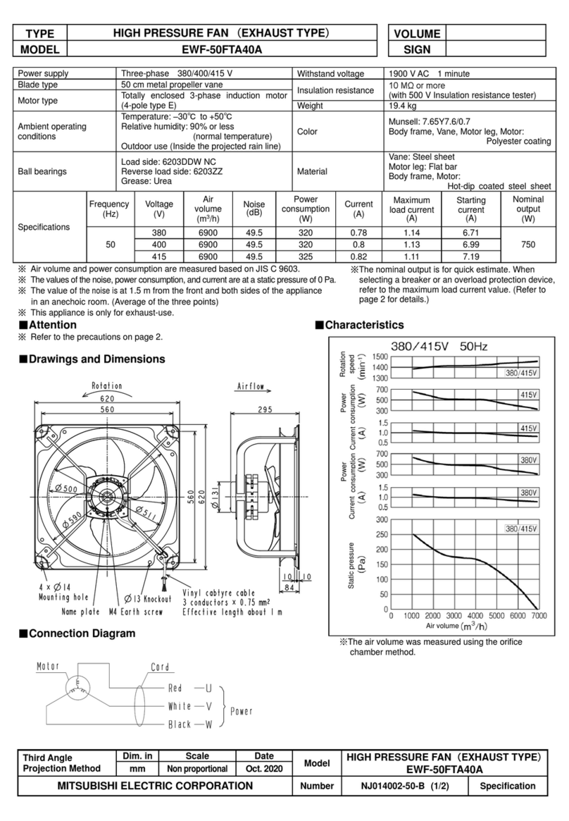
Mitsubishi Electric
Mitsubishi Electric EWF-50FTA40A quick start guide

CellarPro
CellarPro 3000Scmr-EC owner's manual
Maico
Maico ECA 150 ipro Installation and operating instructions

MOBAIR
MOBAIR 2010 owner's manual

Ellington
Ellington E-BFT52ABZ5C installation guide

