Trox Qlci User manual

v1.1 – Issue Date: 02/2023
© 2022 Carson Solutions. All rights reserved.
QLCI with REAR FIN TUBE HEATER ELEMENTS INSTALLATION,
OPERATION, & MAINTENANCE (IOM) MANUAL

2
952.525.2050
www.carsonsolutions.com
info@carsonsolutions.com
TABLE OF CONTENTS
General Information
1.1 Introduction 3
1.2 Safety 3
1.3 Symbols used in this Manual 3
1.4 Receiving, Inspection and Storage 3
Product Description and Installation Preparation
2.1 Product Overview 4
2.2 Construction Description 4
2.3 Application Precautions 4
2.4 Preparation for Installation 4
2.4.1 Items Provided by Installer 4
2.4.2 Unit Weights 4
Installation
3.1 General Procedure 5
3.2 Installation Considerations 5
3.3 Installing the QLCI with Rear Fin Tube
Elements 5-8
3.4 Water Connections 9
3.4.1 Water Connections Identification 9
3.5 Condensate Drain Connection 9
3.6 Air Connection 10
3.7 Flushing the Water Piping System 10
3.8 Filling and Venting the Water System 10
Commissioning
4.1 Waterside Commissioning 11
4.2 Airside Commissioning 11
4.2.1 Airside Commissioning and K-Factor Table 11-12
Maintenance
5.1 Cleaning Instructions 13
5.2 Replacement Parts 13
Troubleshooting
6.1 Symptoms & Solutions 14
Terms and Conditions
7.1 Manufacturer’s Representations
& Warranties 15-16

3
952.525.2050
www.carsonsolutions.com
info@carsonsolutions.com
General Information
Important!
Designation of a danger that can cause personal
injury or damage to property
Warning!
Indicates a potentially dangerous situation for the
product and the environment
Note!
Indicates important notices or information
Carson Solution products should not be removed
from its individual carton for storage. Do not unpack
units until they havebeen moved to the installation
location and just before installation is to begin.
1.1 INTRODUCTION
The QLCI displacement induction ventilation diffusers are designed
to provide air quality and acoustical performance similar to
conventional displacement systems but are designed specifically for
the North American climate. Units are fitted with a series of air
induction nozzles that allow the supply of conventional air (50° to
55°F) to the terminal. These nozzles induce room air through a
cooling and/or reheat hydronic coil to pre-condition the air prior to
mixing with the primary nozzles. The result is a constant volume
(variable temperature) displacement type supply of air to the space.
The QLCI displacement induction ventilation diffusers, when applied
with optional rear fin tube heating elements, delivers warm air to the
space along the exterior wall or large window exposures. Room air
migrates through air pathways to the fin tube elements and the
heated air travels upward due to radiation or buoyant heat
forces. No primary air is used to drive air upward across the fin tube
heating elements. Ventilation air from the central station air handler,
coupled with induced room air provides the necessary ventilation
requirements and total airflow to the space via the lower face diffuser
panel outlets.
The integral hydronic coil within the unit is sized to allow the QLCI
terminal to condition the room while the central system air handler
supplies air at (or near) the mandated space ventilation rate.
Therefore, the central station air handler can supply 100% outside
air while all of the return air from the space is exhausted.
The diffuser uses the primary air energy to induce air through the
hydronic coil and does not contain any moving parts such as, fans,
motors, or compressors to be maintained.
1.2 SAFETY
The customer must use qualified personnel and follow all applicable
building codes and safety regulations when installing, commissioning
and performing maintenance of this product. Eye protection and
gloves should be worn at all times when handling the product.
Consult all local building, occupational safety and other codes
applicable to the installation.
Please pay particular attention to the symbols used throughout the
manual that indicate safety related issues, warnings and important
notices or information; read the complete manual before installation
and be familiar with the meaning of the safety symbols in the next
section 1.3.
1.3 SYMBOLS USED IN THIS MANUAL
When reading this manual, particular attention must be given to the
parts marked with the following symbols:
1.4 RECEIVING, INSPECTION AND STORAGE
All Carson Solutions products are inspected and tested prior to
shipment to ensure the highest quality. Carson Solutions
products are packed and labeled in individual cardboard cartons.
Upon receipt of the product shipment, conduct a thorough
inspection of the outer packaging and pallets for possible
damage. If damage has occurred during shipping, indicate the
damaged items on the delivery papers immediately and inspect
the product contained in those containers for damage.
If damage has occurred during shipping, immediately file a claim
with the carrier.
Refer to the Manufacturer’s Representations and Warranties on
pages 15-16 of this manual for detailed handling instructions
and damage reporting procedures.
Carson Solutions products should be stored in a clean and dry
location. If products remain packaged as delivered (strapped and
wrapped on pallet), they can be stored as delivered (do not stack
pallets). If the packaged products are removed from pallet, they
should not be stacked more than four high.
Packaging is not suitable for outside storage
!
!
F
r
agile!
Handle with care. The diffusor should not be
handled using the water pipes which may cause
damage to the unit.
Important!
You must read all instructions prior to the installation,
operation, or maintenance of this product!

4
952.525.2050
www.carsonsolutions.com
info@carsonsolutions.com
Product Description and Installation Preparation
!
Caution!
Machinery recommended for movement and instal-
lation of QLCI’s. Refer to table below for unit weights
and use caution when removing from packaging.
2.1 PRODUCT OVERVIEW
The QLCI displacement induction ventilation diffusers are designed
specifically for classroom applications. Units can operate in cooling,
heating, and or ventilation modes. In standard cooling or heating
modes, primary air is delivered through a series of induction
nozzles. As ventilation or primary air is fed to the round OA plenum,
the air passes through a series of nozzles, producing both a
relatively high velocity airstream and an area of low pressure
thereby inducing room air through the assembly’s return grill and
across its integral hydronic coil. The air is reconditioned and then
mixed with the primary air prior to being discharged back into the
space via a grill mounted on the lower face of the QLCI unit. In
certain circumstances designers have elected to apply optional rear
fin tube heating elements for either primary or supplemental heating
in the space. Please consult your local Representative or Carson
Solutions directly to evaluate what heating approach is best suited
for your application.
The QLCI displacement induction ventilation diffusers should be
installed in the quantities, sizes and configurations shown on the
project plans and performance schedules.
2.2 CONSTRUCTION DESCRIPTION
The assembly (figure 1) of the QLCI consists of a heat transfer coil
(2- or 4-pipe), primary air inlet (top or side), induction nozzles,
transition connecting duct and sloped condensate tray with
connection. Cabinet structure is constructed of heavy gauge steel
and powdercoated with a fingerprint proof texture paint. Optional
accessories such as bookshelves, utility cabinets, and OA duct
covers may also be supplied by Carson Solutions.
2.3 APPLICATION PRECAUTIONS
When in cooling mode, the entering water temperature to the
QLCI displacement induction ventilation diffuser coil should
be maintained warmer than the space dew point temperature in
order to prevent condensation.
Extreme latent load applications may, however, require lower
chilled water temperatures be used to condense moisture from the
recirculated air during the reconditioning process.Please consult
with a local Representative or Carson Solutions directly for review
of design approaches.
2.4 PREPARATION FOR INSTALLATON
The QLCI displacement induction ventilation diffuser is
manufactured by Carson Solutions with the following
details:
•Single or dual duct connections
•A series of induction nozzles
•Integral heat exchange coil
•Rear wall mounted fin tube elements
•Perforated discharge baffle plate
•Mounting brackets with a ⅜” x 1” slot
•Sloped condensate trays with capped ½” drain
•Architectural cabinets
2.4.1 ITEMS PROVIDED BY INSTALLER
Installer to provide (according to all applicable local
building codes):
•Proper PPE should be used by the installer
•Level and measure equipment
•Tools such as wrenches, plyers, screw drivers, and drills
•A mounting system including 2x4’s and all mounting
hardware for installation
•Hydronic piping system with NPT fittings
•Water flow regulators and strainers if applicable
•Manual shut-off valve for each pipe run
(recommended) supply and return water circuits
(unless factory furnished flexible hoses are included
with product order) or hard connections
•Air-side balancing and/or control devices as specified in
the project plans and specifications
•Recommended hardware to attach each unit to each
other is (4) 5/16-18 x 1” Phillips head truss screws and
(4) 5/16” serrated nuts per QLCI. End wall units only
require 2 of each per QLCI
2.4.2 UNIT WEIGHTS
Add 7% for to values below for water weight
Fin Tube Length Weight with Packaging
3ft
2.25 lbs
4ft
3.00 lbs
5ft
3.75 lbs
6ft
4.50 lbs
7ft
5.25 lbs
8ft
6.00 lbs
QLCI Unit
Size
Weight without
Cabinet
Weight with
Cabinet
4ft
68 lbs 128 lbs
5ft 84 lbs 160 lbs
1500 95 lbs 180 lbs
6ft 101 lbs 192 lbs
2000 122 lbs 232 lbs
8ft 135 lbs 255 lbs
Important!
Installation must be performed by properly trained
and authorized personnel only! Read all
instructions before beginning installation.

5
Installation
952.525.2050
www.carsonsolutions.com
info@carsonsolutions.com
3.1 GENERAL PROCEDURE
The QLCI displacement induction ventilation diffusers should be
installed in quantities, sizes and configurations shown on the project
plans, schedules, and submittals. Deviation from the designed plan
should be avoided as the QLCI unit locations and configurations is
critical to the comfort of the conditioned space. Units are designed
for easy installation and access for maintenance.
3.2 INSTALLATION CONSIDERATIONS
Most classrooms will require the QLCI units are installed along 75%
to 80% of the exterior exposure to provide adequate space
conditioning at noise levels that are compliant with ANSI S12.60.
The supply air duct and vertical pipe runs can be housed in the
class- room walls or may be covered using optional architectural
duct covers and can be accessed through the utility cabinets
provided by Carson Solutions.
3.3 INSTALLING THE QLCI WITH REAR FIN-TUBE
ELEMENTS
STEP 1: INSTALL 2X4’S MOUNTING BOARDS
a.) Secure two 2x4 Mounting Boards to the perimeter wall
making sure they are securely mounted to wall framework
as shown below. (Fasteners supplied by others).
b.) The 2x4 Mounting Boards should run the length of the
QLCI installation (not individual units). The 2x4 Mounting
Boards should stop 1.5” from edge of wall to allow end unit
side panel to set flush against the wall.
STEP 3: INSTALLING REAR FIN TUBE ELEMENTS
a.) Attached Fin Tube Mounting Bracketsto the wall using
wall anchors (Supplied by others). Position each Fin Tube
Mounting Bracket 6”-12” inwards from the Fin Tube
Element pipe ends. Example: A 6ft Fin Tube Element
would have the first bracket at 6”-12” and the second bracket
would be located at 60”-66” from the other end. 3ft to 4ft Fin
Tube Elements require 2 mounting brackets and 5ft to 8ft
Fin Tube Elementsrequire 3 mounting brackets. A bracket
for 5ft-8ft the Fin Tube Elements should be mounted in the
middle of the lengths for support. The Fin Tube Mounting
Brackets should rest directly on top of the 2x4 Mounting
Boards before securing to wall. Refer to project plans for the
appropriate fin tube elements installation lengths and
locations.
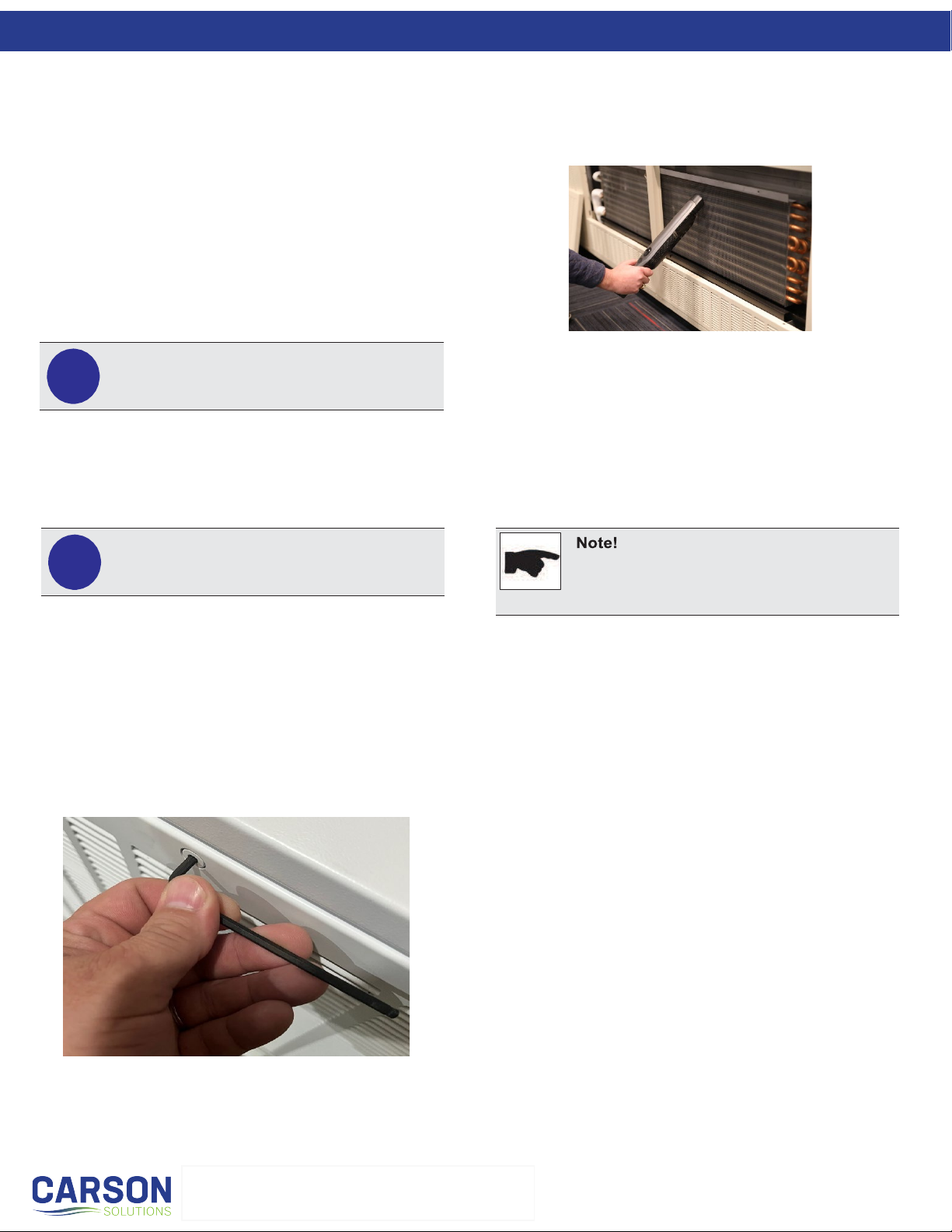
b.) Hang the lower Fin Tube Elementsby placing it gently onto
the Fin Tube Mounting Brackets. The tubes of the Fin
Tube Elements will rest in the V-Groove of the Fin Tube
Mounting Brackets. The Fin Tube Elements are 2.75” fin
width and 2.50” fin height. Make sure the Fin Tube
Elements are positioned in the correct orientation.
Note:
The locations of the 2x4’s is very important to
install in the locations provided in the
dimensions in Section 3.3.

6
Installation
952.525.2050
www.carsonsolutions.com
info@carsonsolutions.com
c.) Hang the upper Fin Tube Elementsby placing it gently
onto the Fin Tube Mounting Brackets. The tubes of the
Fin Tube Elements will rest in the V-Groove of the Fin
Tube Mounting Brackets. The Fin Tube Elements are
2.75” fin width and 2.50” fin height. Make sure the Fin Tube
Elements are positioned in the correct orientation.
d.) Repeat Steps (a-c) for additional Fin Tube Elements
according to the room layout of the project plans. Note:
There may be plastic clips on the Fin Tube Elements from
the manufacture, these can be discarded.
e.) Once all Fin Tube Elements are installed, begin joining all
piping together (Straight pipe and fittings supplied by others).
The lower Fin Tube Elements are to be the Supply run, and
the upper Fin Tube Elements are to be the Return run. A
Loop should be used to connect the last lower Fin Tube
Element to the upper return row of Fin Tube Elements.
f.) Connect the Supply and Return piping to complete the
circuit. If using a BUC, it will be necessary to install the
BUC first before the main Supply and Return piping is ran
and connected.
STEP 2: Example install QLCI hydronic water piping
a.) Typically, a BUC is used where the water pipes are dropped
from the ceiling along a wall perpendicular to the exposure
and are secured to the wall between the mounting boards as
shown below. Additional valves, regulators, and strainer
may be required. See project plans and specifications
for more information.

7
Installation
952.525.2050
www.carsonsolutions.com
info@carsonsolutions.com
b.) Install threaded ½˝ NPT connections (provided by others)
on each pipe or solder straight end connections 2˝ to 3˝ from
the point where the QLCI units connect to each other along
the wall as shown below.
c.) Once all the piping is connected, test for leaks and
insulate piping. Refer to project plans for insulation
specifications. Use standard plumbing practices and test for
leaks once the piping is complete. See Section 4.1 for
pressure ratings.
STEP 3: Attaching the QLCI units to the wall
a.) Locate the (2) socket head screws on the face of each upper
face panel. Loosen the locking screws using an 5/32” Allen
Wrench and remove the units upper face panels (as shown
below). Do not use a power driver to loosen or tighten
latches. Do not allow the upper face panels to fall as this
could cause damage to the panel surface. Remove lower
panel as needed by removing the (2) TEK screw.
b.) Position the first QLCI unit (nearest the supply air duct)
against the wall. Secure units to the 2x4 Mounting Boards
by driving ⅜” lag bolts and ⅜”flat washers through the unit’s
four (4) Mounting Brackets as shown below.
STEP 4: Positioning and connecting the remaining units
a.) Repeat Step 3 to mount the remaining units to the wall and to
make water connections.
b.) Connect the QLCI units together by sliding the connector
sleeve from the adjacent QLCI unit onto the entry spigot and
seal the connection as described below in Section 3.5.

8
Installation
952.525.2050
www.carsonsolutions.com
info@carsonsolutions.com
c.) Attached each QLCI to another using (4) 5/16-18 x 1”
Phillips head truss screws and (4) 5/16” Serrated nuts per
QLCI. End wall units only require 2 of each per QLCI. Locate
the upper and lower holes as shown. Insert hardware and
tighten the units together.
d.) If inspection of the Fin Tube Elements is needed, remove
the Rear Fin Tube Element Grill on the back of the QLCI.
Locate the (2) socket head screws on the top of each Rear
Fin Tube Element Grill. Loosen the locking screws using
an 5/32” Allen Wrench and remove the QLCI Rear Fin Tube
Element Grill as shown below. Make sure when placing the
QLCI Rear Fin Tube Element Grill back in place that the
side tabs interlock with the metal flanges.
e.) Alternative piping method 1: Units can be placed on roller
carts and connected to each other first. The pipework can be
connected to the back of the QLCI’s, and piping connections
can be connected to each other before mounting the entire run
of QLCI’s to the wall mounted 2x4’s as shown below.
f.) Alternative piping method 2: QLCI units can allow the piping
runs to be in the front of the units above the hydronic coil. This
allows the QLCI to be mounted to the 2x4’s first, then connect
the ductwork before making the piping connections. The
feeding pipework can be routed through the side wall
knockouts. QLCI’s and piping connections can be connected in
the front as shown below.
STEP 5: Connecting to water supply
a.) Connect the unit’s hydronic coil to
the water piping using flexible
braided stainless-steel hoses (½˝
female NPT’s to connect to coil).
In most applications, flexible
braided stainless-steel hoses
require 90° elbows. Hard copper
piping may also be used. Proper
sealing techniques should be
applied. Refer to Division 23
Section 23 21 13 “Hydronic
Piping”, connect coils to supply
with shutoff valve, strainer, control
valve, and union or flange, and to
return with balancing valve and
union or flange.
b.) The vertical chilled/hot water pipes
are connected via flexible hoses
run through a pipe work knockout
on the top or side of the unit.
c.) Piping should be insulated and properly labeled in
accordance with local building codes as shown below.
It is recommended to use
these holes on the QLCI
top and bottom panels to
attach each unit together.

9
952.525.2050
www.carsonsolutions.com
info@carsonsolutions.com
Installation
Extreme Caution!
Do NOT over-tighten NPT fittings.
Applying excessive force on the water pipes may
damage the hydronic coil and is not covered under
warranty.
3.4 WATER CONNECTIONS
The QLCI unit is fitted with four water pipes which terminate in
½” NPT threaded male connections. Each coil is factory tested
for leakage and provided clean and capped. Caps shall not be
removed unit piping installation is in process.
Note:
When installing a two-pipe design, connect only the
outside pipes if four-pipe coil was supplied.
STEP 1:
Identify the warm and/or
chilled water supply
connections on the QLCI
unit. See Section 3.4.1.
STEP 2:
Remove the plastic caps
before making the final
water connections.
STEP 3:
Make the water connections to the hydronic coil piping using
flexible braided stainless-steel hoses (½˝ female NPT’s to
connect to coil). Hard copper piping may also be used. Proper
sealing techniques should be applied. Refer to Division 23
Section 23 21 13 “Hydronic Piping”, connect coils to supply
with shutoff valve, strainer, control valve, and union or flange,
and to return with balancing valve and union or flange.
Carson Solutions optional Stainless Steel Flexible Hoses
(contact your factory rep to purchase).
3.4.1 WATER CONNECTIONS IDENTIFICATION
Piping connections for standard 2-pipe and 4-pipe QLCI
displacement induction ventilation diffusers to be operated
and connected as shown below.
3.5 CONDENSATE DRAIN CONNECTION
The QLCI unit is fitted with a sloped condensate drain tray with
an anti-clogging ½” plastic drainpipe fitting (½” OD). Each
drainpipe is located on the right side of the QLCI when looking
at the unit from the front. The drainpipe fitting should be
connected to a condensate line or pumping system as specified
in project documents. Each drain comes capped from the
factory. Remove cap prior to pumping each drainpipe fitting.

10
952.525.2050
www.carsonsolutions.com
info@carsonsolutions.com
Installation
There should be no high points to create
air pockets within the system.
Note:
Use ONLY non-chilled water when filling up the
system! Cold water can cause immediate
condensation on the pipes. Warm water contains
less oxygen which can limit venting to some extent.
3.6 AIR CONNECTION
STEP 1:
Note:
QLCI displacement induction ventilation diffusers
operate at higher terminal pressures than diffusers in
standard VAV systems therefore the ductwork and
connections feeding the diffuser must be thoroughly
sealed to prevent excessive leakage.
The air connections should include a minimum of three duct
diameter lengths of straight ductwork upstream of the QLCI
connection to ensure laminar flow and prevent noise generation.
Straight ductwork connections will yield a reliable pressure port
measurement.
Air connections can be made with either hard-pipe (most common)
or with flexible duct. If using flexible duct, limit duct length to a
maximum of 5ft.
Using the supplied transition collar to connect each QLCI together.
Properly seal ductwork with either foil HVAC aluminum tape or with
duct sealant mastic. The inner duct connection must be fully sealed
to prevent leakage and loss of performance.
Ensure there is an airtight connection between the supply duct and
each QLCI duct interconnections. Duct connections should meet
SMACNA class B standard up to 2 in. W.G. Refer to Division 23 –
Heating, Ventilation and Air Conditioning (HVAC) Section 23 31
13.01 “Metal Ducts” and or Section 23 07 13 “Duct Insulation” for
additional information.
3.7 FLUSHING THE WATER PIPING SYSTEM
Before flushing the water system, close all valves that isolate the
QLCI units and flush the main piping system first. Refer to
Division 23 Section 23 25 00 “Pipe Cleaning, Flushing, and
Chemical Treatment”.
3.8 FILLING AND VENTING THE WATER SYSTEM
To ensure easy venting, the main pipes should be installed at a
higher level than the QLCI units. The horizontal pipes should be
installed rising slightly towards the venting points.
Before filling, all shut-off and control valves must be in the fully
open position. The pumps should not be running during the
filling processes (static filling). Continuous venting is necessary
during this process. The installation of both manual and
automatic venting systems is recommended. The pump should
only be started when filling is complete. To remove all air from
the system, the majority (>75%) of the system should be closed
so that the water can circulate at a sufficient rate. When each
section is full, it should be closed, and the procedure repeated
throughout the system.

11
952.525.2050
www.carsonsolutions.com
info@carsonsolutions.com
Commissioning
Important:
Commissioning is to be performed by properly
trained and authorized personnel only!
!
Note:
Do not attempt to read the total discharge airflow rate
using ahood or any other device that adds down-
stream pressure to the unit, as it will reduce the
amount of induction and give false readings.
The total supply air flow (primary +induced) cannot
be measured.
The constraints detailed in the tables below are for
standard QLCI. For QLCI’s with non-standard
nozzle configurations, contact Carson Solutions
directly.
4.1 WATERSIDE COMMISSIONING
•Fully purge the complete hydronic system of air prior to
commissioning.
•Carefully inspect the system for leaks, paying particular
attention to the connections.
•Carefully inspect flexible hose for leaks, if applicable.
•For the face coils normal operating pressure is rated at 250 psig
max up to 300°F. The maximum working pressure should not
exceed 360 psi.
•If equipped, the fin-tube elements the minimum flow rate of
1GPM ranging from 110°F to 220°F at a pressure drop of 47
Millinches per foot. Maximum flowrate at 4GPM at the same
operation temperature ranges at a pressure drop of 525
Millinches per foot. The maximum working pressure is 200
psig.
4.2 AIRSIDE COMMISSIONING
NOTE: Using a traverse duct calculation of the supply duct before
the QLCI will not guarantee that the diffuser is properly balanced
because performance is based on internal plenum pressure.
4.2.1 AIRSIDE COMMISSIONING AND K-FACTOR TABLE
STEP 1
Locate the (2) socket head screws on the top of the upper left
face panel. Loosen the locking screws using an 5/32”Allen
Wrench and remove the units upper face panels (as shown
below). Do not use a power driver to loosen or tighten latches.
Do not allow the upper face panels to fall as this could cause
damage to the panel surface.
STEP 2
Use the commissioning tube to measure the internal pressure
of the plenum.
Note:
The QLCI unit is not provided with any water flow
control or measuring devices, therefore the pipe
work system should be fitted with sufficient
balancing aids to enable adjustment of the flow rate.

12
952.525.2050
www.carsonsolutions.com
info@carsonsolutions.com
Commissioning
STEP 3
The primary air volume in CFM can be calculated with this
formula and the K-Factor value in the charts below: Data on the
charts below are given at Standard Atmosphere at sea level.
The primary air volume in CFM can be calculated with this formula:
CFM = K x √ΔP
CFM = primary airflow (CFM)
K = constant - read from Table below
ΔP = static pressure measured in primary air
chamber (in. W.G.)
Example: Size 1500mm QLCI, 2R-nozzle
measured static pressure of 0.295 in. W.G.
K = 221 (from Table 2)
CFM = 213 x √0.295
= 120.0 CFM
STEP 4
Make necessary adjustments to the balancing damper for the
desired scheduled static pressure to the measured result.
Adjusting the balancing damper should be used for trimming only.
Re-installed front face panels.
Refer to Division 23 Section 23 05 93 “Testing, Adjusting, and
Balancing” for additional procedures for displacement unit,
adjusting and balancing.
Volume Flow Controller (optional) general information:
If a volume flow rate control is required, a volume flow
controller (supplied by others) may be installed in a constant
volume system. See manufactures information specifications
for further details.
Carson Solutions offers a range of volume flow rate
controllers. Please contact Carson Solutions for more
information.
13
952.525.2050
www.carsonsolutions.com
info@carsonsolutions.com
Maintenance
Important!
Maintenance is to be performed by properly trained
and authorized personnel only!
!
Important!
Wear eye protection and gloves.
Product includes sharp edges and burrs.
!
Strong or abrasive chemical detergents should not
be used as they may cause damage to the paint
finish.
5.1 CLEANING INSTRUCTIONS
QLCI units contain no moving or consumable parts, therefore the
maintenance requirements are limited to periodic inspection for leak-
age and occasional cleaning of the hydronic coil, front face panel
and the condensate tray.
The accumulation of dust on the hydronic coil will eventually restrict
the airflow through the coil, reducing cooling and heating
performance.
The inspection frequency is subject to the environmental conditions
and occupancy levels. It is recommended that the QLCI units be
inspected on an annual basis until a scheduled maintenance pattern
is established.
Properly maintain water conditions which prevent corrosion of
copper tubing If included in the system design, check the
condensate sensors or humidity sensors according to sensor
manufacturer’s methods and schedule.
To clean the hydronic coil:
STEP 1
Locate the (2) socket head screws on the top of each upper face
panel. Loosen the locking screws using an 5/32” Allen Wrench
and remove the units upper face panels (as shown below). Do
not use a power driver to loosen or tighten latches. Do not allow
the upper face panels to fall as this could cause damage to the
panel surface.
STEP 2
Using a soft nozzle brush attachment, gently vacuum in the
direction of the coil fin to remove any accumulated dust. Be
careful not to bend or damage any fins. A fin comb can be
used to straighten any bent fins.
STEP 3
After cleaning the coils, replace the unit face panels by
tightening locking screws with 5/32” Allen Wrench.
To clean the QLCI unit:
When necessary, the cabinet can be cleaned using a mild
detergent diluted with warm water. Apply with a soft cloth,
rinse, and wipe dry.
To clean the condensate tray:
If necessary, the condensate drip tray can be cleaned
using a small amount of disinfectant applied with a soft
cloth. Wipe dry.
5.2 REPLACEMENT PARTS
The QLCI displacement induction ventilation diffuser
contains no serviceable or consumable parts. Contact
Carson Solutions for more information.
14
952.525.2050
www.carsonsolutions.com
info@carsonsolutions.com
Troubleshooting
6.1 SYMPTOMS & SOLUTIONS
SYMPTOM PROBABLE CAUSE SOLUTION
LOSS OF AIRFLOW
Obstruction on front face panel or
hydronic coil
Remove front face panel and inspect/clean grill
and hydronic coil as necessary
Air connection detached from diffuser Inspect attachment hardware and
reconnect ductwork
Obstruction in primary air plenum Remove primary air connection and
check for debris
Air dampers incorrectly set Inspect and adjust air damper as necessary
Faulty or incorrectly set air handling unit Inspect and re-commission air
handling unit (by certified contractor)
REDUCED
COOLING OR HEATING
Reduced cooling or heating performance Confirm primary airflow is at designed
CFM or above
Obstruction on front face panel or hydronic coil Remove front face panel and inspect/clean grill
and hydronic coil as necessary
Loss of water circulation through hydronic coil Inspect control valves and check flow using
system test points
CONDENSATION ON
PIPE-WORK OR
HYDRONIC COIL
Chilled water temperature too low Measure chilled water temperature and reset
to design value
Incorrect primary air temperature or condition
Measure room humidity level. If humidity
is higher than design condition, the primary air
is failing to control room humidity. The air
handling unit must be set so the primary air is
dry enough to offset the latent gains.
Primary air volume too low
Measure primary air volume using procedure
described in section 4.2.1 Increase air volume
design figure.

15
952.525.2050
www.carsonsolutions.com
info@carsonsolutions.com
Warranties
7.1 MANUFACTURER’S REPRESENTATIONS &
WARRANTIES
CARSON DESIGN MANUFACTURING (CDM), INC. DBA (CARSON
SOLUTIONS) TERMS & CONDITIONS OF SALE Version 01-01-22 ALL
SALES ARE SUBJECT TO THESE TERMS AND CONDITIONS OF SALES
(“TERMS”) AND AS CONTAINED IN CDM’S INVOICE AND ARE ALSO
SUBJECT TO CDM’S CREDIT AND OTHER POLICIES AND
PROCEDURES, WHICH ARE HEREBY INCORPORATED BY REFERENCE
AND SUBJECT TO CHANGE.
1. TERMS TO GOVERN: These Terms shall be binding upon CDM Inc, and
its subsidiaries and affiliates ("Seller") and the buyer (“Buyer”). No
modification, amendment or change, whether in Buyer’s purchase order,
shipping release forms or otherwise shall obligate Seller, unless authorized in
writing by Seller. Any different or inconsistent terms and conditions contained
in Buyer’s forms whether issued before or after Seller’s quotation are hereby
expressly superseded by these Terms.
2. ACCEPTANCE & PRICES: Any proposal offered by Seller to Buyer is valid
for sixty (60) days from Seller’s issuance. Upon the expiration of sixty (60)
days or sooner if revoked by Seller, the proposal shall expire. Pricing shall
remain valid for Seller’s products shipped within 90 days from the date of
Seller’s acceptance. Thereafter, prices are subject to change. Prices include
transportation charges predicated on a single shipment and any partial
shipments may result in additional cost to Buyer. Seller reserves the right, at
any time, to withdraw a bid, quote or a price that contains an error.
3. PAYMENT & TAXES: Upon credit approval, payment terms for Products
shipped hereunder or labor performed will be thirty (30) days net with no
retainages unless contrary
terms appear on the face hereof or otherwise expressly agreed to in writing by
Seller. Should Buyer default in the timely payment to Seller of sums due on an
order, Seller is entitled to any remedies provided in these Terms or by law. If
Buyer fails to pay any amounts when due, Buyer shall pay Seller interest
thereon at a periodic rate of the lesser of one and one- half percent (1.5%) per
month or the maximum allowable legal interest rate, along with all costs and
expenses (including without limitation mechanics lien or bond, collection
expenses, reasonable attorneys' fees, filing and service fees and
disbursements and Court costs) incurred by Seller. Buyer is responsible for all
sales, customs, or use tax imposed by any governmental agency, including,
but not limited to, Federal, State, Local or international authorities, payable on
the transaction under any applicable statute, except those taxes due as a
result of Seller’s gross profits. If Seller is not timely paid or Buyer is otherwise
in default, Seller reserves the right to pause or terminate any work or services
in process and/or reschedule any delivery at any time.
4. PERFORMANCE: Seller shall be obligated to furnish only the Products or
labor described in the applicable purchase order or acknowledgement and
agreed to in writing. The duty to perform under any order on the part of Seller
and the price thereof is subject to the approval of its Credit Department, and is
contingent upon the absence of strikes, accidents, floods, act(s) of terrorism,
war, fires, fuel shortages, the inability to procure materials from the usual
sources of supply, the requirements of the US Government (through the use
of priorities or preference or any other manner) that Seller divert either the
material or the furnished Product to the direct or indirect benefit of the US
Government, or upon any like or unlike cause beyond the reasonable control
of Seller. Upon disapproval of the Credit Department or upon the occurrence
of any such event, Seller may delay performance or, at its option, renegotiate
prices and terms and conditions of sale with Buyer. If Seller elects to
renegotiate and Seller and Buyer are unable to agree on revised prices or
terms, Seller may cancel without any liability.
5. SHIPMENT & RISK OF LOSS: Shipment dates are estimates only, FOB
factory. Title and risk of loss shall pass to Buyer upon Seller’s delivery to
carrier. Customers may only
make their own shipping arrangements with Seller’s agreement. Seller shall
advise when the Products have been completed and send an invoice at that
time. All Product must be picked up by Buyer within 30 days of Seller’s
completion of manufacture. Seller specifically rejects any order containing a
time is of the essence clause or liquidated damage penalties for late
shipments. Seller is not responsible for loss of goods from shortages,
damages or transit delays. Any claims for damage in shipment, mis-delivery,
loss of the Products or other damage shall be the responsibility of and filed by
Buyer.
6. CHANGES, CANCELLATION & RETURNS: Changes requested by Buyer
following Seller’s acceptance of order must be approved by Seller in writing
and may result in an increase in price by Seller to recover all labor and
material costs, including normal overhead and profit. If any portion of a Seller
accepted order is cancelled by Buyer without default on the part of Seller or
without Seller's written consent, Buyer shall be liable to Seller for cancellation
charges including, but not limited to, Seller's incurred costs and the profit
Seller would have realized from the transaction had the agreement not been
breached by Buyer. Products shall not be returned except by written
permission of Seller pursuant to Seller’s return policy.
7. AUTHORITY OF AGENTS: No agent, employee or representative of Seller
has the authority to bind Seller to any affirmation, representation or warranty
concerning the Product or labor sold, except for Seller’s authorized agents,
employees or representatives.
8. INDEMNITY: Seller shall protect and indemnify Buyer from and against all
claims, damages, judgments and loss solely arising from Seller’s infringement
or alleged infringement of any United States patent by any of the articles or
material delivered hereunder, provided that in the event of suit or threat of suit
for patent infringement, Seller shall promptly be notified and given full
opportunity to negotiate a settlement. Seller does not warrant against
infringement by reason of Buyer's design of the articles or the use thereof in
combination with other materials, or in the operation of any process. In the
event of litigation, Buyer agrees reasonably to cooperate with Seller. All
parties concerned shall be entitled, in connection with any proceeding under
the provisions of this Article, to be represented by counsel at their own
expense. Buyer shall defend, indemnify and hold Seller harmless from any
personal injury, wrongful death or property damage caused in whole or in part
by Buyer’s breach, negligent or intentional act(s).
9. LIMITED WARRANTY: Seller warrants that at the time of delivery and for a
period of twelve (12) months from the initial startup (“Start-Up”), or eighteen
(18) months from date of shipment, whichever is less, Products will be free
from defects in material and manufacture provided that Products have been
installed with proper Start-Up, maintained and operated under normal
conditions for service in accordance with the instructions of Seller, and that
Products have the capacities and ratings set forth in Seller's design
specifications. No warranty is made against corrosion, erosion or deterioration.
At Seller’s option, Seller's obligations and liabilities under this warranty are
limited to repair of Products or replacement of components for Products not
conforming to this warranty. This Limited warranty does not cover labor for
component repair or replacement. Once Seller’s service department has been
notified and approved any warranty related service work, Seller will repair or
replace components as needed and ship FOB factory. Seller shall not be
obligated to pay for the cost of lost refrigerant or Glycol. Consumable parts
and Products that are consumable in nature are explicitly excluded from this
warranty. Consumables include, but are not limited to, filters, glycol and
refrigerant. No warranty or liability whatever shall attach to Seller until full
payment has been received. No warranty herein extended shall apply to repair
or correction of conditions arising from improper or incorrectly connected air
duct, piping, wiring, power supply, blown fuses, freezing, improper Product
control when programmed by non-Seller controls, or personnel, or by anyone
other than Seller employee or its representative. Operation of Products for
temporary conditioning of a building during construction without the written
consent of an officer of the Seller immediately voids any warranty coverage. If
the Product is replaced, the replacement may not be new, but will be in good
working order and at least functionally equivalent to the item or Product
replaced. The replacement assumes the warranty status of the replaced
Product. The warranty period does not restart. THIS LIMITED WARRANTY IS
VOIDED BY MISUSE, NEGLECT, FAILURE TO FOLLOW INSTRUCTIONS
OR SELLER’S MANUALS OR TAMPERING WITH, THE PRODUCTS
PERFORMED BY ANY PERSON OR ENTITY OTHER THAN SELLER
WITHOUT SELLER’S PRIOR WRITTEN APPROVAL OR ANY USE OF
REPLACEMENT PARTS NOT SUPPLIED BY SELLER. THE WARRANTY
AND LIABILITY SET FORTH HEREIN REPRESENT BUYER’S EXCLUSIVE
REMEDY AND ARE IN LIEU OF ALL OTHER WARRANTIES AND
LIABILITIES WHETHER IN CONTRACT, TORT, WARRANTY OR IN
NEGLIGENCE, EXPRESSED OR IMPLIED, IN LAW OR IN FACT,
INCLUDING IMPLIED WARRANTIES OF MERCHANTABILITY AND
FITNESS FOR A PARTICULAR USE. SELLER PROVIDES NO
INDEPENDENT WARRANTY FOR THIRD PARTY PRODUCTS OR
COMPONENTS SOLD TOGETHER OR INCORPORATED WITH SELLER’S
PRODUCT(S).

16
952.525.2050
www.carsonsolutions.com
info@carsonsolutions.com
Warranties
10. LIABILITY DISCLAIMER: TO THE MAXIMUM EXTENT PERMITTED BY
LAW, SELLER’S TOTAL LIABILITY FOR CLAIMS, REGARDLESS
OF THE FORM OF ACTION OR THEORY OF LIABILITY (INCLUDING
CONTRACT, TORT OR WARRANTY), SHALL BE LIMITED TO THE FEES
PAID TO SELLER BY BUYER FOR THE PRODUCTS OR LABOR THAT
WAS THE PROXIMATE CAUSE OF THE DAMAGE. IN NO EVENT SHALL
SELLER BE LIABLE TO BUYER FOR ANY INCIDENTAL,
CONSEQUENTIAL, SPECIAL, PUNITIVE, OR INDIRECT DAMAGES OF
ANY KIND (INCLUDING, WITHOUT LIMITATION, LOST PROFITS, LOSS
OF USE, OR CLAIMS OF THIRD PARTIES) THAT MIGHT OCCUR AS A
RESULT OF THE PERFORMANCE OR BREACH OF THE AGREEMENT OR
IN ANY WAY ARISING OUT OF OR IN CONNECTION WITH THE
AGREEMENT WHETHER BY CONTRACT, TORT, WARRANTY OR
OTHERWISE. SELLER SHALL NOT BE LIABLE OR RESPONSIBLE FOR
ANY CRANE, RIGGING, LABOR OR OTHER CHARGES OR DAMAGES OF
ANY KIND OR NATURE CAUSED IN WHOLE OR IN PART BY DELAYS IN
SHIPMENT OR SELLER’S BREACH.
11. ASSIGNMENT: Buyer may not assign or transfer this agreement. Seller
may assign its rights or obligations under this Agreement in the event of a
merger or change of control of Seller.
12. GOVERNING LAW: This Agreement shall be governed and construed in
accordance with the laws State of Minnesota. Buyer consents to jurisdiction in
the Circuit Court of
Hennepin County, Minnesota. Each party consents to that choice of law and
jurisdiction and irrevocably waives any objection to same.
13. EXPORT CONTROLS: Buyer shall comply with the export laws and
regulations of the United States. Buyer agrees it shall not export or enter into
an agreement for the export any goods from Seller to any prohibited or
embargoed country or to any denied, blocked or restricted person or entity.
14. MISCELLANEOUS: Seller’s waiver or failure to enforce the terms of this
Agreement shall not constitute a waiver of Seller’s rights. The prevailing party
may recover their reasonable attorney fees and reasonable out-of-pocket
expenses.
Table of contents
Other Trox Fan manuals


Popular Fan manuals by other brands


Challenge
Challenge FF-450A instruction manual

NuTone
NuTone QTRE090FL Specification sheet

Inspire
Inspire Ana LM JB36301 Assembly manual

Fanimation
Fanimation Air Shadow FP810 Series owner's manual

Trisa electronics
Trisa electronics Star Line 9326.47 Instructions for use

Vortice
Vortice NORDIK HVLS SUPER BLADE E instruction manual


