manuals.online logo
Brands
  1. Home
  2. •
  3. Brands
  4. •
  5. Troy-Bilt
  6. •
  7. Lawn Mower
  8. •
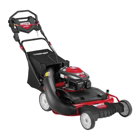
  9. Troy-Bilt Wide-Cut F753B User manual

Troy-Bilt Wide-Cut F753B User manual

This manual suits for next models

1

Other Troy-Bilt Lawn Mower manuals

Troy-Bilt Super Bronco 60TG User manual

Troy-Bilt

Troy-Bilt Super Bronco 60TG User manual

Troy-Bilt TBWC28 Guide

Troy-Bilt

Troy-Bilt TBWC28 Guide

Troy-Bilt 560 Series User manual

Troy-Bilt

Troy-Bilt 560 Series User manual

Troy-Bilt T-106 User manual

Troy-Bilt

Troy-Bilt T-106 User manual

Troy-Bilt 546 User manual

Troy-Bilt

Troy-Bilt 546 User manual

Troy-Bilt LTX-2146 User manual

Troy-Bilt

Troy-Bilt LTX-2146 User manual

Troy-Bilt SmartSpeed 566 User manual

Troy-Bilt

Troy-Bilt SmartSpeed 566 User manual

Troy-Bilt Wide-Cut E753B User manual

Troy-Bilt

Troy-Bilt Wide-Cut E753B User manual

Troy-Bilt 439 Series User manual

Troy-Bilt

Troy-Bilt 439 Series User manual

Troy-Bilt 440 Series User manual

Troy-Bilt

Troy-Bilt 440 Series User manual

Troy-Bilt J860 Series User manual

Troy-Bilt

Troy-Bilt J860 Series User manual

Troy-Bilt TB515 EC User manual

Troy-Bilt

Troy-Bilt TB515 EC User manual

Troy-Bilt HYDROSTATIC LAWN TRACTOR - HORSE 769-06304 User manual

Troy-Bilt

Troy-Bilt HYDROSTATIC LAWN TRACTOR - HORSE 769-06304 User manual

Troy-Bilt 429 User manual

Troy-Bilt

Troy-Bilt 429 User manual

Troy-Bilt 52057 User manual

Troy-Bilt

Troy-Bilt 52057 User manual

Troy-Bilt 836 series User manual

Troy-Bilt

Troy-Bilt 836 series User manual

Troy-Bilt 809 User manual

Troy-Bilt

Troy-Bilt 809 User manual

Troy-Bilt SmartSpeed 566 User manual

Troy-Bilt

Troy-Bilt SmartSpeed 566 User manual

Troy-Bilt 106 User manual

Troy-Bilt

Troy-Bilt 106 User manual

Troy-Bilt 13BC26JD563 User manual

Troy-Bilt

Troy-Bilt 13BC26JD563 User manual

Troy-Bilt 18AEB9C7766 Guide

Troy-Bilt

Troy-Bilt 18AEB9C7766 Guide

Troy-Bilt 556 User manual

Troy-Bilt

Troy-Bilt 556 User manual

Troy-Bilt 12AE449 Series Guide

Troy-Bilt

Troy-Bilt 12AE449 Series Guide

Troy-Bilt Mustang 42E XP User manual

Troy-Bilt

Troy-Bilt Mustang 42E XP User manual

Popular Lawn Mower manuals by other brands

Toro 20047 Operator's manual

Toro

Toro 20047 Operator's manual

Toro Greensmaster TriFlex 3300 Operator's manual

Toro

Toro Greensmaster TriFlex 3300 Operator's manual

Global garden products 72 Workshop manual

Global garden products

Global garden products 72 Workshop manual

EINHELL 01045 operating instructions

EINHELL

EINHELL 01045 operating instructions

Toro Greensmaster 3120 Operator's manual

Toro

Toro Greensmaster 3120 Operator's manual

Baroness LM315GC Owner's operating manual

Baroness

Baroness LM315GC Owner's operating manual

GreenWorks Tools 25157 user manual

GreenWorks Tools

GreenWorks Tools 25157 user manual

Etesia MVEHH user manual

Etesia

Etesia MVEHH user manual

Husqvarna LTH125 owner's manual

Husqvarna

Husqvarna LTH125 owner's manual

Gravely 915034 - ZT1640 Owner's/operator's manual

Gravely

Gravely 915034 - ZT1640 Owner's/operator's manual

Jacobsen 63281 Technical manual

Jacobsen

Jacobsen 63281 Technical manual

GreenWorks Pro MO802524 Operator's manual

GreenWorks Pro

GreenWorks Pro MO802524 Operator's manual

Toro TimeMaster 20976 Operator's manual

Toro

Toro TimeMaster 20976 Operator's manual

Deutz-Allis 3000 Series parts manual

Deutz-Allis

Deutz-Allis 3000 Series parts manual

Craftsman 917.9998C owner's manual

Craftsman

Craftsman 917.9998C owner's manual

jobmate YT9108 user manual

jobmate

jobmate YT9108 user manual

Yard force GM R40A instructions

Yard force

Yard force GM R40A instructions

Husqvarna R 419TsX AWD Operator's manual

Husqvarna

Husqvarna R 419TsX AWD Operator's manual

manuals.online logo
manuals.online logoBrands
  • About & Mission
  • Contact us
  • Privacy Policy
  • Terms and Conditions

Copyright 2025 Manuals.Online. All Rights Reserved.

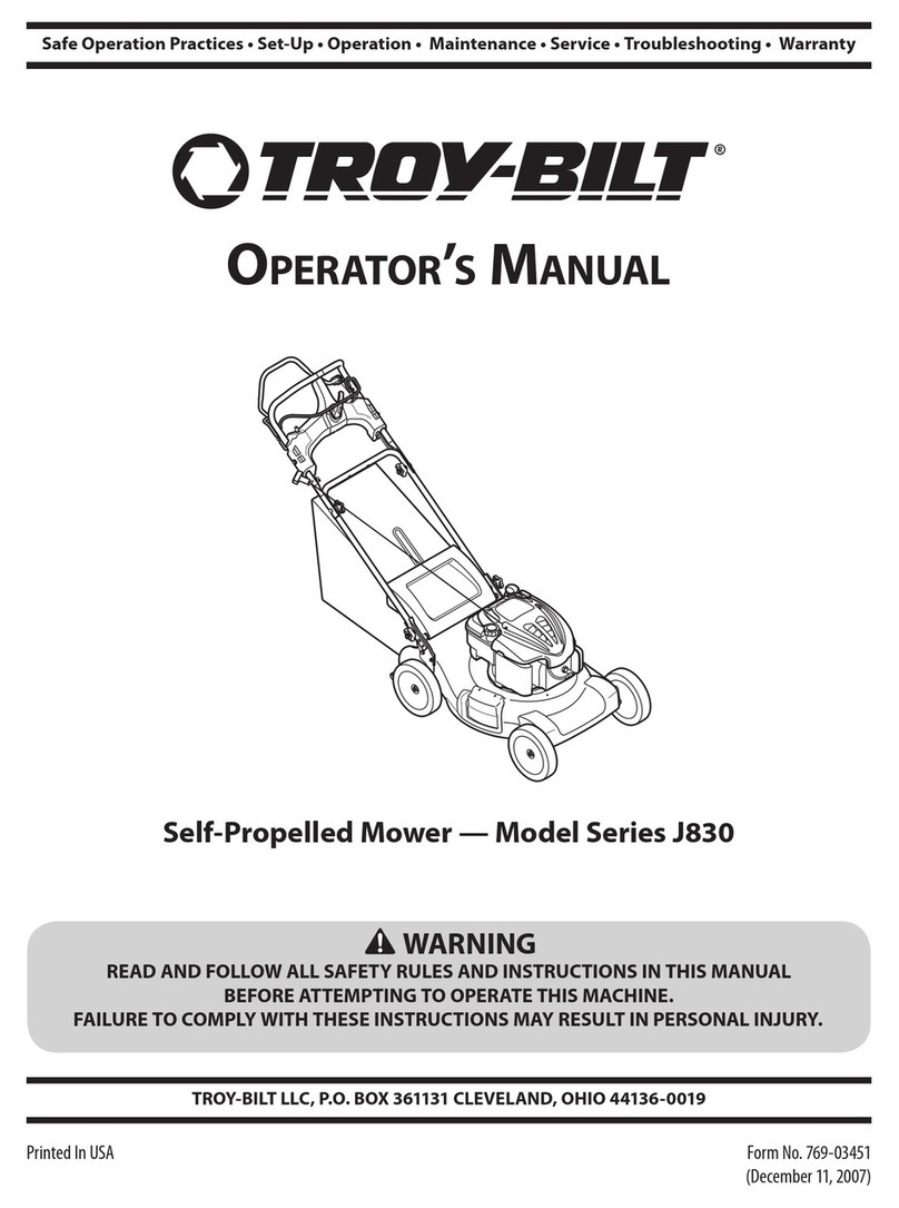
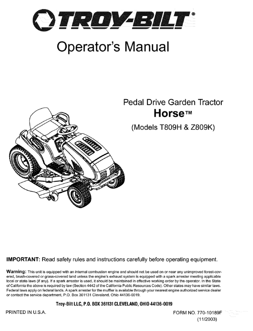
0TRtII BILT --
Operator's Manual
Wide-CutTM 33"
Combination Mower
Models 753B
F753B
(fuel tank styles vary by engine model)
IMPORTANT:READ SAFETY RULES AND INSTRUCTIONS CAREFULLY
Warning: This unit is equipped with an internal combustion engine and should not be used on or near any unimproved forest-covered, brush-cov-
ered or grass-covered land unless the engine's exhaust system is equipped with a spark arrester meeting applicable local or state laws (if any). If a
spark arrester is used, it should be maintained in effective working order by the operator. In the State of California the above is required by law
(Section 4442 of the California Public Resources Code). Other states may have similar laws. Federal laws apply on federal lands. A spark arrester
for the muffler is available by contacting the service department at Troy-Bilt LLC, P.O. Box 361131 Cleveland, Ohio 44136-0019.
TROY-BILT LLC, P.O. BOX 361131, CLEVELAND, OH 44136-0019
PRINTED IN USA FORM NO. 770-10602E
(03/2003)
TABLEOFCONTENTS
Content Page
Safety ................................................................... 1
Assembly................................................................. 4
Features and Controls....................................................... 8
Operation ................................................................ 11
Maintenance .............................................................. 16
Off-Season Storage ........................................................ 24
Lubrications............................................................... 25
Troubleshooting ........................................................... 27
Parts List................................................................. 28
Warrany Information........................................................ BackCover
FINDINGMODELNUMBER
This Operator's Manual is an important part of your new Wide-Cut TM mower. It will help you assemble, prepare and
maintain the unit for best performance. Please read and understand what it says.
Before you start assembling your new equipment, please locate the model plate on the equipment and copy the infor-
mation from it in the space provided below. This information is very important if you need help from our Customer
Support Department or an authorized dealer.
You can locate the model number by looking at the rear surface of the tine shield. A sample model plate is ex-
plained below. For future reference, please copy the model number and the serial number of the equipment in
the space below
OTRItV BILT. TROY-BILT LLC
P. 0. BOX 361131
www.troybilt.com CLEVELAND, 0H44136
330-558-7220
_. 866-840-6483_
Copy Model Number Here
Copy Serial Number Here
ENGINEINFORMATION
The engine manufacturer is responsible for all engine-related issues with regards to performance, power-rating,
specifications, warranty and service. Please refer to the engine manufacturer's Owner's/Operator's Manual packed
separately with your unit for more information.
CALLINGCUSTOMERSUPPORT
If you have difficulty assembling this product or have any questions regarding the controls, operation or maintenance
of this unit, please call the Customer Support Department.
Call 1- (330) 558-7220 or 1- (866) 840-6483 to reach a Customer Support representative. Please have
your unit's model number and serial number ready when you call. See previous section to locate this in-
formation. You will be asked to enter the serial number in order to process your call.
Safety
WARNING:
The engine exhaust from this product contains
chemicals known to the State of California
to cause cancer, birth defects, or other reproduc-
tive harm.
SafetyAlertSymbol
_, his is a safety alert symbol. It is used in this
Owner's Manual to alert you to potential
hazards. Wheneveryou seethis symbol, readand obeythe
safety messagethat follows it. Failureto obey the safety
message could result in personal injury or property
damage.
IMPORTANT
Safe Operation Practicesfor Walk-Behind Mowers
This cutting machine is capable of amputating hands and feet and throwing objects. Failure to observethe
following safety instructionscould result in serious injury or death.
I. GENERALOPERATION
1.
.
Read,understand,andfollow all in-
structionson the machineandin the
manuals.Bethoroughlyfamiliar with
thecontrolsandthe proper useof
themower beforestarting.
Donot put handsor feet nearor
under rotatingparts.Keepclearof
themower bladeand discharge
openingatall times.
3. Onlyallow responsibleindividuals,
whoarefamiliar with the instruc-
tions,to operatethe mower.
4. Clearthe areaof objectssuch as
rocks,toys, wire, bones,sticks, etc.,
which couldbe pickedupand
thrown bythe blade.
.
5. Besurethe areais clearof other
peoplebeforemowing.Stopmower
if anyoneentersthearea. Keepby-
standersatleast25 feetawayfrom
the areaofoperation.
6. Donot operatethe mowerwhen
barefootor wearingopensandals.
Alwayswearsubstantialfoot wear.
Donot pull mower backwards
unlessabsolutelynecessary.Look
downand behindbeforeand while
moving backwards.
8. Donot operatethe mowerwithout
properguards,plates,grasscatcher
or othersafetyprotectivedevicesin
place.
9. Referto providedinstructionsfor
properoperationand installationof
accessories.Onlyuseaccessories
approvedbyGardenWay
Incorporated.
10. Stopthebladewhencrossinggravel
drives,walks, or roads.
11. Stoptheengineand disconnectthe
sparkplug wirefrom thesparkplug
wheneveryou leavethe unit, before
cleaningthe moweror unclogging
the chute.
12. Shutthe engineoff, waituntilthe
blade comesto a completestop,and
disconnectthespark plugwire be-
fore installing or removingthe
mulchercoveror the optionalgrass
catcher. Makecertainthat thegrass
catcherissecurelyattachedbefore
operatingthe mower.Emptythe
grass catcheraftereachuse-
decomposingdebriscouldgenerate
enoughheatto catchfire.
13. Mow in daylightor goodartificial
light.
14. Donot operatethemowerwhile
underthe influenceofalcoholor
drugs.
Section1:Safety
15.
16.
17.
Neveroperatemowerin wet grass.
Alwaysbesureofyour footing; keep
a firm hold onthe handleandwalk;
never run.
DisengagetheWheelDriveLeveron
self-propelledmodelsbeforestarting
theengine.
If the unitshouldstartto vibrateab-
normally,stop theengineanddis-
connectthe sparkplug wire. Then
checkimmediatelyfor thecause.
Vibrationis generallya warningof
trouble.
18. Alwayswearsafetygogglesor safety
glasseswith sideshieldswhenoper-
ating mower.
19. Watchfor traffic whenoperating
near,or whencrossingroadways.
20. Neverattemptto carrychildrenor
otherpassengerson themower.
Theycouldfall off and beseriously
injured,or theycouldinterferewith
thesafeoperationofthe mower.
21. Checkthe operationofthe Operator
PresenceControlBarbeforeeach
use.Seethe MaintenanceSectionof
this manualfor instructions. If the
enginerunslongerthanthreesec-
ondsafter theOperatorPresence
Control Baris released,the system
is not working properly. Immediately
contactyour localservicedealeror
thefactory TechnicalService
Departmentfor instructions. Donot
usethe moweruntilthe mechanism
is repaired.
22. Themoweris equippedwith a safety
dischargechute,comeswith special
mulchercovers,and offersan op-
tionalgrass catcher. Thesafetydis-
chargechute mustbeworking prop-
erly atalltimes. Neverattemptto
disconnector otherwisecausethis
dischargechuteto ceaseworking. If
used,mulchercover or grass
catcherattachmentmust beinstalled
properlyandfunction correctly. Do
not useyour equipmentotherwise.
23. Neverrun theenginein an enclosed
area.Engineexhaustcontainscarbon
monoxide,a deadlygasthat is odor-
less,colorless,andtasteless.Always
runtheengineoutdoorsand make
surethereisadequateventilation.
II. SLOPEOPERATION IV.SERVICE
Slopesare a majorfactorrelatedto
slipandfall accidentswhichcanresult
in severeinjury. All slopesrequire
extracaution.Ifyoufeel uneasyona
slope,donotmowit.
DO:
Mow acrossthefaceof slopes;never
upand down. Exerciseextremecau-
tion whenchangingdirection on
slopes.Avoidslopesgreaterthan
150.
Removeobjectssuch asrocks,tree
limbs,etc.
Watchfor holes,ruts, or bumps.Tall
grass canhideobstacles.
DONOT:
1. Useextracarein handlinggasoline
andotherfuels.Theyareflammable
andtheir vaporsare explosive.
a) Useonlyan approvedcontainer.
b) Neverremovegascapor add
fuelwhentheengineis running.
Allowengineto coolbeforerefu-
eling.Donot smoke.
c) Neverrefuelthe machine
indoors.
d) Neverstore themachineor fuel
containerinsidewherethereis
an openflame,such asawater
heater,etc.
e) Movemowerawayfrom any
gasolinefumesbeforestarting
theengine.
2. Neverrunan engineinsideaclosed
area.
III. CHILDREN
Tragicaccidentscanoccuriftheopera-
torisnotalerttothepresenceofchil-
dren.Childrenare oftenattractedtothe
mowerandtothemowingactivity.
Neverassumethatchildrenwill remain
whereyoulastsawthem.
1. Keepchildrenout ofthe mowing
areaand underthewatchful careof
a responsibleadult.
Bealertandturn moweroff if chil-
drenenterthearea.
.
3.
4. Neverallowchildrento operatethe
mower.
5. Useextracarewhenapproaching
blind corners,shrubs,trees,or other
objectsthat mayobscurevision.
Beforeandwhile movingbackwards,
look behindand downfor small
children.
3. Nevermakeadjustmentsor repairs
with theenginerunning.Disconnect
thesparkplug wireand keepthe
wireawayfrom the plugto prevent
accidentalstarting.
Keepall nuts andbolts,especially
thebladeattachmentbolts,tight and
keepequipmentin goodcondition.
Nevertamperwith safety devices.
Checktheir operationregularly.
6. Keepmowerfreeof grass,leavesor
otherdebrisbuild-up.Cleanup oil or
fuelspillage.Allow mowerto cool
beforestoring.
7. Afterstriking an object,stop theen-
gineand disconnectthesparkplug
wire. Inspectthe mowerand repair,
if necessary,beforerestarting.
8. Neverattemptto makemowercut-
ting heightadjustmentswhilethe
engineis running.
9. Grasscatchercomponentsaresub-
jectto wear, damageanddeteriora-
tion, which couldexposemoving
parts or allowobjectsto bethrown.
Frequentlycheckcomponentsand
replacewith factory recommended
parts,whennecessary.
Donot mowneardrop-offs, ditches,
or embankments.Theoperatorcould
loosefooting or balance. 4.
Donot mowexcessivelysteepslopes.
Donot mowon wet grass.Reduced
footing could causeslipping. 5.
Section1:Safety
13.
10. Mower bladesaresharpandcan
cut.Wrapthe bladeor weargloves,
and useextracautionwhenservic-
ing them.
11. Donotchangetheenginegovernor
settingor overspeedthe engine.
12. Donottouch enginepartswhich
may behotfrom operation.Allow
partsto cool completelybeforein-
specting,cleaningor repairingthe
mower.
14.
Toaccessthe undersideofthe
mower,tip the mower rearward.Do
nottip the mowerforward or on ei-
ther of its sides,unlessspecifically
advisedto do soin this manual.
Maintainor replacesafetyand in-
structionaldecals. Referto the sep-
aratePartsCatalogfor replacement
decalinformation.
15. Forunitsequippedwith electric
start:
a) Batteriesproduceexplosive
gases.Keepsparks,flame,
cigarettes,etc.,away. Ventilate
theareawhenchargingthe bat-
tery.Donotchargethebatteryin
anairtight space.
b) Donot usea batterycharger
otherthanthe oneprovidedwith
the mower.
c) Thebatterycontainstoxic mate-
rials. Donotdamagethe battery
case.If thecaseis brokenor
damaged,avoidcontactwith the
batterycontents.
d) Properlydisposeof adamaged
or worn outbattery.Checkwith
localauthoritiesfor proper dis-
posalmethods.
e) Donotshort circuit the battery.
Severeburnsandfire canresult.
SAFETYDECALS
Makecertainall safetydecalsonthis equipmentare keptcleanandin good condition. Thedecalsareshown (at reducedsizes)
below. If you needa replacementdecal,pleasereferto the PartsCatalogthat accompaniedthis Manual.
Onleftside ofmowerdeck
OnControlPanel (for electricstartmodel)
Beneathbelt/pulleycover
OnControlPanel (for recoilstartmodel)
DANQER
Ondischargechute
Assembly
ASSEMBLYSTEPS
To preventpersonalinjuryor property
damage, do not attempt to start the
engine until all assembly steps are
complete and you have read and
understand the safety, controls and
operatinginstructionsinthismanual.
INTRODUCTION
Pleasecarefullyfollow theseassembly
stepsto properlyprepareyour machine
for use. Werecommendthat you read
this Sectionin its entiretybeforebegin-
ningassembly.
STEP1: Unpacking Mower
NOTE:LEFTand RIGHTsides ofthe unit
areasviewedfrom the operator'sposi-
tion behindthehandlebars.
1. Cutstraps, if present,securingunit
to pallet. Leaveuniton palletduring as-
sembly(to safelyremoveunitfrom pal-
let, wait until youhavecompletedas-
semblysteps1-4).
2. Removeanyprotectivepackaging
from aroundthe handlebars.Cutthe
plastictie strapsholdingthecontrol rods
and struts tothe handlebars.
NOTE:All referencesto left, right,front
and rearof the machineare determined
bystandingbehindthehandlebarsand
facingthe direction offorward travel.
INSPECTIONAFTERDELIVERY
Inspectthe shippingcrateand machine
immediatelyafterdelivery. Makesure
neitherthecarton/cratenor thecontents
havebeendamaged.
If youfind or suspectanydamage,con-
tact thecarrier(truckingcompany)
immediately. Informthem of thespecific
damageandthatyou wish to filea claim.
To protectyour rights, besureto put
this in writing to thecarrierwithin 15
days. Thecarrierwill letyou knowhow
to proceedwith your claim. Pleaseletus
knowif you needanyassistance.
STEP2: Attach Handlebars
to Engine Deck
NOTE:Fourscrews(D, Figure2-2) are
usedto connectthehandlebarsto the
enginedeck. At thefactory,two of these
screws (front) arethreadeddirectlyinto
lock nuts weldedto thebacksidesof the
deck.Theremainingtwo screws (rear)
securethe lowerhandleto the deck.
1. Removeandsavethe two 5/16"-18x
3/4"screws (front) mentionedin the
NOTEabove.
2. Loosen,butdo NOTremove,the two
5/16"-18x 3/4"screws(rear).Leavethe
cardboardinsertfound betweentheleft-
hand handlebarandenginedeck,in
place.
3. Carefullypivot thehandlebarsover
•WireCutter
• Two7/16" Wrenches
• 3/8" Wrench
• 1/2" Wrench
• Scissorsor PenKnife
theengineandpositionthe handlebar
TOOLS/MATERIALSNEEDED: ends(E,Figure2-2) againstthesides of
theenginedeck.Donotalloowthehan-
dlebarsto rubagainsttheenginewhile
pivoting them.
4. Looselysecuretheright-handhandle-
barendto thedeck byreinsertingthe
screw(D, Figure2-2) removedearlier.
• Needle-nosePliers Donot securethe left-handhandleat
• TireGauge this pointin assembly.
5. Removethecardboardinsertfrom
betweentheleft-handhandlebarand
enginedeck
8. Removethenutfrom the lowerscrew
(B,Figure2-1) which securesthecon-
soleto thehandlebaron theleft-hand
Figure2-1
D D ,
i
Figure2-2: Attachhandlebarsandstruts
toenginedeck.
sideofthe unit.
7. Positiona handlebarstrut's smaller
hole (A,Figure2-1) overthescrew(B,
Figure 2-1) on the INSIDEofthe con-
sole,with the strut's flat sideagainstthe
console.
8. Usingthe nut removedearlier,secure
thestrut to theconsole/handlebar.
9. Align thelooseendof theleft-hand
handlebarstrut (A,Figure2-2) overthe
front holein the handlebarend.Secure
thestrut and handlebarto thedeckwith
the5/16"-18x3/4" screw(D, Figure2-2)
removedearlier.
10. Removethe screw (front) that is
looselysecuringthe right-handhandle-
barendto thedeck.and repeat6-9 on
the right-handsideofthe unit.
11. On bothsidesofthe unit, securely
tightenthe screws(D, Figure2-2) atthe
lowerendsofthe handlebarbeforetight-
eningthescrews (B & F,Figure2-1) on
theconsole.
Section2: Assembly
STEP3 ATTACHINGTHEBATTERY
CABLES(MODEL F753B)
Thepositivebatteryterminal is marked
Pos.(+). Thenegativebatteryterminal is
markedNeg.(-).
Themowerisshippedwith thepositive
(Red)cablesecuredto thepositiveter-
minal (+)onthe battery.Attachthe
ground (Black)cableto the negativeter-
minal (-) onthe battery,asfollows:
1. Removethe plasticbatterycover (G,
Figure.2-3) byunthreadingthe two wing
nuts (H, Figure. 2-3) which secure it to
the batteryhold-down rods (I, Figure.2-
3)
2. Remove the hex bolt and hex nut
from the groundcable/heavyblackwire
(E,Figure.2-3).
3. Securetheground cableto thenega-
tive batteryterminal (-) with the boltand
hexnutjust removed.
IMPORTANT:
•If the batteryis putinto serviceafter
the dateshown ontop of battery,
chargethe batteryasinstructedin the
Maintenencesectionof this manual
prior to operatingthetiller.
STEP4: Attach Control Rods
A. AttachWheelDriveControlRod
1. Locatethewheeldrivecontrol rod (F,
Figures2-4A & 2-7) and removethe an-
gledendfrom theleft handlebarby re-
movingthe hairpinclip whichsecuresit
to theWheelDriveControllever(V,
Figure2-4A)
2. Atleft sideof enginedeck,insert
swivelblock (H,Figures2-4 & 2-5) on
wheeldrivecontrol rod into wheeldrive
control arm(U, Figure2-4).
3. Adda5/16"washer(A, Figure2-4)
andsecurewith a hairpinclip (B).
4. Atupperend ofcontrol rod,re-insert
the angledend intotheWheelDrive
Controllever(V,Figure2-4A) and re-
attach with hairpinclip (BB) removed
earlier.
B.AttachOperatorPresenceControl
Rod
1. LocatetheOperatorPresenceControl
rod (E,Figures.2-4 and 2-5). At bottom
ofcontrol rod,insert swivelblock (G,
Figures2-4 & 2-5) into control arm (T,
Figure2-4).
HBlack
(NegativeCable)
H
Red /
(PositiveCable)
Figure2-3: Connectwireterminalstobatteryterminals.
Controlrodsare adjusted at the fac-
tory andshouldnot requireadditional
adjustmentduringassembly.Afteras-
sembling unit, control rod
adjustment should be checked (and
re-adjusted,ifnecessary)accordingto
informationin MaintenanceSection.
Failureto follow this instructioncould
result in severe personal injury or
propertydamage.
2. Add one5/16"washerand secure
with hairpinclip.
C.AttachBladeDriveControlRod
1. Locatethe bladedrivecontrol rod (C,
Figure2-5). Insertoneendof control rod
into bladedrivebracket(D,Figure2-5).
Add one5/16"washerandattachwith
hairpinclip (CC).
2. Insertthe otherendof rod into bot-
tom endof BladeDriveControl lever(J,
Figure2-5). Add one5/16"washerand
attachwith hairpin clip (AA).
D. AttachandAdjustGearSelectLever
NOTE:Theretainingplate(N,Figure2-5)
mentionedin thefollowing stepsis se-
curedto the rearofthe mowerwith two
screws (O,Figure2-5) and1/4"-20 lock-
nuts.Removethe retainingplateand
saveit, along with thetwo screws,be-
fore proceedingwith assembly.
W
H A,B _G
Figure2-4:Left-handcontrolrodsdetail.
Section2: Assembly
BB
Figure2-4A:Attachwheeldrivecontrolrod
tolever.
1. Removethevinyl grip (B,Figure2-6)
from the gearselectlever(I). Placethe
woodedgeagainsttheedgeofthe grip
andslowly pull off thegrip.
2. Insertnylon bushing(Z, Figure2-6)
up into console(L).
3. Slidespringandwashers(J)down
ontogearselectlever.
4. Insertgearselectlever(I) upthrough
nylonbushing(Z)in handlebarconsole
(L).Guidepin (K)ongearselectleverinto
grooveinshift quadrant(P).
5. Holdlowerpartof gearselectlever(I,
Figure2-7) againstbracket(M). Position
retainingplate(N), removedearlier,as
shown in Figure2-7 (platebelow
bracket). Secureplatewith two 1/4"-20x
1/2"screws(0) and1/4"-20 Iocknutsre-
movedearlier.
6. Slidegrip (B, Figure2-6) backonto
gearselectlever(I).
7. Rotategearselectlever(I, Figures2-
6 & 2-7) clockwiseuntilspur (K - short
rod) ongearselectrod stopsin theneu-
tral position detenton theshift pattern
quadrant(Figure2-6).
8. Moveshift arm (X,Figure2-7) from
sideto sideas necessaryintoeachtrans-
missiongeardetentuntil transmissionis
in neutral.
NOTE:Movingshift arm(X) allthewayto
theleft,andthenonenotch backtothe
right, shouldputtransmissioninto neu-
tral. Whentransmissionisin neutral,unit
will movefreely whenpushedwhilehold-
ingthe OperatorPresenceControllever
(W, Figure2-5) down.If transmissionis
NOTin neutral,therewill beaslight drag
on thewheelswhenpushingunit.
WJ
V
F
G N
Figure2-5: Rearviewofcontrolrods.
0M
C
f2
K
Pin(K)mustbeinthisdetent
whentransmissionneutralis --_
adjusted.
Figure2-6: Detail-GearSelectLeverin Neutral(N) position.
6
Section2: Assembly
9. Whenshift arm (X)is in neutralposi-
tion, rotateshift link (P)toward endof
gearselectleverrod (I). Adjustlength
of shift link (P) asnecessaryto fit into
hole in bottomof gearselectlever(I).
NOTE:Pin (K) on GearSelectLever(I)
must beheld inthe neutralposition
detentonthe shift quadrant(seeFigure
2-6) whileshift link(P, Figure2-7) is
adjusted.
10. Inserthookedendof shift link (P,
Figure2-7) into holein bottomend of
gearselectlever(I) andsecurewith
hairpinclip (Q).
NOTE:It may benecessaryto lift gear
selectlever(I) to install shift link (P).
11. Removeunitfrom shippingcrate.
Toremove,hold downOperator
PresenceControllever(W, Figure2-5)
which releasesthewheelbrake.
12. With unit on levelground,hold
downOperatorPresenceControllever
(W, Figure2-5) and pushunitforward
and backward.Thewheelsshouldmove
freely.If not, adjust lengthofshift link
(P, Figure2-7) as necessary.
13. Putthe GearSelectLeverin neutral
(N), releaseall of thecontrol leversand
try to pushthe unitforward and back-
ward. Thewheelsshould notturn. If
they doturn, an adjustmentisneces-
sary. DONOTOPERATETHEUNIT
UNTILTHEWHEELBRAKEMECHANISM
HASBEENADJUSTEDAND ISWORK-
INGPROPERLY.See"WheelBrake
Adjustment"in Section5 "Maintenance."
STEP5: Secure Wire Harness
1. Atthe unattachedendof theelectrical
wire harness,therearefour wires at-
tachedto a largeplasticconnectorand
two wires attachedto a small plastic
connector.. Plugthelargeconnector
intothe bottom ofthe ignitionkeyswitch
that is locatedon the undersideofthe
handlebarconsole(notpictured).
3. Usetwo cableties to securethewire
STEP6: Check Motor Oil Level
1. Movemowerto a levelarea.Press
and hold OperatorPresenceControl
lever(W,Figure2-5) to movemower.
2. Themoweris shippedwith oil in the
engine.However,youMUSTcheckthe
oil levelaccordingto theinstructionspro-
videdintheseparateEngineOwner's
Manualincludedinthe unit'sliterature
packagebeforestartingthemower.
Do not use the mower if the wheels
continue to turn after releasing the
Operator Presence Control and the
WheelDriveControl.
Severe personal injury or property
damagecouldresult if this instruction
isnotfollowed.
I f o
Figure2-7: Detail- TransmissionNeutralAdjustment.
• Keepoil levelatthe FULLmarkon the
dipstick to avoidenginedamage.
• Changeoil accordingtoscheduleand
instructionsin Section5 "Maintenance."
STEP7: Check Tire Pressure
1. Useatire gaugeto checktheair
pressurein the reartires. Theair pres-
sureshould bebetween15-20 PSI(20
PSImaximum).
2. Keepbothtires equallyinflatedto
helppreventmachinefrom pullingto
oneside.
STEP8: After Assemblingand
Before UsingUnit
1. Readthis entireOwner'sManualfor
harnessto theright handlebarandaway o.
from any movingparts. Placethe ties propersaTety,operationand mainte-
anequaldistanceapart, nanceinformation.
2. Makesuresparkplug wire iscon-
nectedto sparkplug beforestarting unit.
FeaturesandControls
Before operating mower, be sure to
read all safety, controlsand operating
instructions in this Manual and on
decalslocatedonmachine.
Severe personal injury or property
damage couldresultit this instruction
isnotfollowed.
IMPORTANT: THE MOWER IS
EQUIPPED WITH A BLADE-BRAKE-
CLUTCHCONTROLSYSTEMWHICH IS
DESIGNED TO STOP THE MOWER
BLADESWITHIN THREE(3) SECONDS
AFTERRELEASEOF THE OPERATOR
PRESENCECONTROL. THIS SYSTEM
WILL STOPTHEBLADESBUTNOTTHE
ENGINE.THEREFORE,YOUCANDISEN-
GAGETHE BLADEDRIVEAT ANYTIME
WITHOUT HAVING TO STOP AND
RESTARTTHEENGINE.THIS FEATURE
IS PARTICULARLYUSEFULWHENYOU
NEEDTO CROSSGRAVELDRIVESOR
ROUGHTERRAIN AND YOU DO NOT
WANT THE SPINNING BLADES
TO STRIKE STONES OR HIDDEN
OBSTACLES.
MOWERFEATURESAND
CONTROLS
This sectiondescribesthevarious
featuresand controlson the unit. Refer
to the nextsection"Operation"for
detailedoperatinginstructions. Also,
readthe separateEngineOwner's
Manualfor a detailedexplanationofthe
proper useofthe enginecontrols.
Operator Presence Control
TheOperatorPresenceControllever
(A, Figure3-1) regulatesthe operationof
the rearwheelbrakeandtheseparate
BladeDriveControl. Alwaysengagethis
control beforeengagingtheseparate
bladedriveor wheeldrivecontrols.
Alwaysdisengagethis control before
startingtheengine.
Toengagethe OperatorPresence
Control,pressand holdthe leveragainst
the handlebargrip. Doingso releases
the brakeon therearwheels,allowing
the wheelsto turn. Theengagedposition
alsopermitstheseparateBladeDrive
Controlto lock in its engagedposition
(allowsthe mowerbladesto turn).
Releasingthe lever(disengaged
position) appliesthe rearwheelbrake
andquicklystopsthewheels.Releasing
the leverwill alsodisengagethe Blade
DriveControl,which will applya brake
that stopsthe bladeswithinthree (3)
seconds.
Blade Drive Control
Usethis lever(B,Figure3-1) to en-
gagedriveto themower blades.
Toengagethe blades,first engagethe
OperatorPresenceControl (A,Figure3-
1). Then,pushthespring-loadedBlade
DriveControllever(B)forward until it
stays in theengagedposition.
Tostop the blades,releasethe
OperatorPresenceControl (A). Doingso
will disengagethe BladeDriveControl
(B) andautomaticallyapplythe brake
that stopsthe blades.
AlwaysdisengagetheBladeDrive
Controlbeforestartingtheengine. This
helpsto ensurethatthe bladeswill not
startturning whentheenginestarts.
The blade-brake-clutchcontrolsystem
shouldstop the mower bladeswithin
three (3) secondsafter release of the
OperatorPresenceControl.
If the bladesdo not stopwithin three
(3) seconds, put the Engine Throttle
Control in the STOP position.
Disconnectthe sparkplugwire and do
not operatethe moweruntil the blade-
brake-clutchcontrolsystemhas been
repaired.
B- BLADE
DRIVECONTROL
Disengage
Engage
C- GEAR
SELECTLEVER
A-OPERATOR
PRESENCECONTROL
Disengage
Engage
Figure3-1