manuals.online logo
Brands
  1. Home
  2. •
  3. Brands
  4. •
  5. Troy-Bilt
  6. •
  7. Trimmer
  8. •
  9. Troy-Bilt 645A Super Bronco User manual

Troy-Bilt 645A Super Bronco User manual

Other manuals for 645A Super Bronco

2

This manual suits for next models

1

Other Troy-Bilt Trimmer manuals

Troy-Bilt TB525CS User manual

Troy-Bilt

Troy-Bilt TB525CS User manual

Troy-Bilt TB590 EC User manual

Troy-Bilt

Troy-Bilt TB590 EC User manual

Troy-Bilt TB6044 XP User manual

Troy-Bilt

Troy-Bilt TB6044 XP User manual

Troy-Bilt AST TB25CS User manual

Troy-Bilt

Troy-Bilt AST TB25CS User manual

Troy-Bilt TB22 User manual

Troy-Bilt

Troy-Bilt TB22 User manual

Troy-Bilt TBAH User manual

Troy-Bilt

Troy-Bilt TBAH User manual

Troy-Bilt TB22 EC User manual

Troy-Bilt

Troy-Bilt TB22 EC User manual

Troy-Bilt TB525 EC User manual

Troy-Bilt

Troy-Bilt TB525 EC User manual

Troy-Bilt TB425CS User manual

Troy-Bilt

Troy-Bilt TB425CS User manual

Troy-Bilt SpringAssist TB25ET User manual

Troy-Bilt

Troy-Bilt SpringAssist TB25ET User manual

Troy-Bilt 52064 User manual

Troy-Bilt

Troy-Bilt 52064 User manual

Troy-Bilt TB525CS User manual

Troy-Bilt

Troy-Bilt TB525CS User manual

Troy-Bilt TB635 EC Installation and operating instructions

Troy-Bilt

Troy-Bilt TB635 EC Installation and operating instructions

Troy-Bilt TB 35 EC User manual

Troy-Bilt

Troy-Bilt TB 35 EC User manual

Troy-Bilt TB25C5 User manual

Troy-Bilt

Troy-Bilt TB25C5 User manual

Troy-Bilt TB495 User manual

Troy-Bilt

Troy-Bilt TB495 User manual

Troy-Bilt Pony TB465SS User manual

Troy-Bilt

Troy-Bilt Pony TB465SS User manual

Troy-Bilt 52027 Setup guide

Troy-Bilt

Troy-Bilt 52027 Setup guide

Troy-Bilt TB475SS User manual

Troy-Bilt

Troy-Bilt TB475SS User manual

Troy-Bilt TB90BC User manual

Troy-Bilt

Troy-Bilt TB90BC User manual

Troy-Bilt TB55B User manual

Troy-Bilt

Troy-Bilt TB55B User manual

Troy-Bilt AST TB25CS User manual

Troy-Bilt

Troy-Bilt AST TB25CS User manual

Troy-Bilt TB32 User manual

Troy-Bilt

Troy-Bilt TB32 User manual

Troy-Bilt Pony TB465SS User manual

Troy-Bilt

Troy-Bilt Pony TB465SS User manual

Popular Trimmer manuals by other brands

LawnMaster LML261 Safety and operating manual

LawnMaster

LawnMaster LML261 Safety and operating manual

McCulloch TrimMac ST+ instruction manual

McCulloch

McCulloch TrimMac ST+ instruction manual

Gardena EasyCut 48 PLUS operating instructions

Gardena

Gardena EasyCut 48 PLUS operating instructions

Gardena ComfortCut 450/25 user manual

Gardena

Gardena ComfortCut 450/25 user manual

Twose TF500 Operator's manual

Twose

Twose TF500 Operator's manual

Echo SRM-230 parts catalog

Echo

Echo SRM-230 parts catalog

netta PHTEG06AA-450 manual

netta

netta PHTEG06AA-450 manual

Total TGTLI20301 manual

Total

Total TGTLI20301 manual

Maestro MR680 owner's manual

Maestro

Maestro MR680 owner's manual

Andis Experience D4X specification

Andis

Andis Experience D4X specification

Flymo EASICUT 5500 Original instructions

Flymo

Flymo EASICUT 5500 Original instructions

Homelite F-3040 user manual

Homelite

Homelite F-3040 user manual

Ozito LTR-301 instruction manual

Ozito

Ozito LTR-301 instruction manual

Flymo Contour Cordless 24 V Original instructions

Flymo

Flymo Contour Cordless 24 V Original instructions

McCulloch T22 LS Operator's manual

McCulloch

McCulloch T22 LS Operator's manual

COCKRAFT PRO HL36-S Original instructions

COCKRAFT

COCKRAFT PRO HL36-S Original instructions

Weed Eater BC2400 instruction manual

Weed Eater

Weed Eater BC2400 instruction manual

Grizzly CT 1800 Li Instructions for use

Grizzly

Grizzly CT 1800 Li Instructions for use

manuals.online logo
manuals.online logoBrands
  • About & Mission
  • Contact us
  • Privacy Policy
  • Terms and Conditions

Copyright 2025 Manuals.Online. All Rights Reserved.

0TRtlI BILT°
Operator's Manual
Rear-tine Tiller Models
644H--Bronco TM
645A--Bronco TM
Model 644H Shown (bumper syles vary)
IMPORTANT:READ SAFETY RULES AND INSTRUCTIONS CAREFULLY
Warning: This unit is equipped with an internal combustion engine and should not be used on or near any unimproved forest-covered, brush-
covered or grass-covered land unless the engine's exhaust system is equipped with a spark arrester meeting applicable local or state laws (if any).
If a spark arrester is used, it should be maintained in effective working order by the operator. In the State of California the above is required by law
(Section 4442 of the California Public Resources Code). Other states may have similar laws. Federal laws apply on federal lands. A spark arrester
for the muffler is available by contacting the service department at Troy-Bilt LLC, P.O. Box 361131 Cleveland, Ohio 44136-0019.
TROY-BILT LLC, P.O. BOX 361131, CLEVELAND, OH 44136-0019
PRINTED IN USA FROM NO. 769-00585A
(01/2003)
TABLE OF CONTENTS
Content Page
Calling Customer Support .................................................... 2
Safety ................................................................... 3
Assembly................................................................. 6
Features and Controls ....................................................... 10
Operation ................................................................ 13
Maintenance .............................................................. 19
Off-Season Storage ........................................................ 24
Troubleshooting ........................................................... 25
Parts List................................................................. 26
Warrany Information ........................................................ Back Cover
FINDINGMODELNUMBER
This Operator's Manual is an important part of your new Rear-tineTiller. It wilt help you assemble, prepare and
maintain the unit for best performance. Please read and understand what itsays.
Before you start assembling your new equipment, please locate the model plate on the equipment and copy the infor-
mation from it in the space provided below. This information is very important if you need help from our Customer
Support Department or an authorized dealer.
You can locate the model number by looking at the rear surface of the tine shield. A sample model plate is
explained below. For future reference, please copy the model number and the serial number of the equipment
in the space below
OTRII BILT" TROY-BILT LLC
P. O. BOX 361131
www.troybilt.com CLEVELAND,OH44136
330-558-7220
•866-840-6483j
Copy Model Number Here
Copy Serial Number Here
ENGINEINFORMATION
The engine manufacturer is responsible for all engine-related issues with regards to performance, power-rating, speci-
fications, warranty and service. Please refer to the engine manufacturer's Owner's/Operator's Manual packed sepa-
rately with your unit for more information.
CALLING CUSTOMER SUPPORT
If you have difficulty assembling this product or have any questions regarding the controls, operation or maintenance
of this unit, please call the Customer Support Department.
Call 1- (330) 558-7220 or 1- (866) 840-6483 to reach a Customer Support representative. Please have
your unit's model number and serial number ready when you call. See previous section to locate this
information. You will be asked to enter the serial number in order to process your call ..
2
nSafety
SPARKARRESTERWARNINGTORESIDENTSOFCALIFORNIAANDSEVERALOTHERSTATES
UnderCalifornia law,and under the laws of severalother states,you are not permitted to operatean
internalcombustion engineusing hydrocarbon fuelson anyforest, brush, hay, grain, or grass
covered land;or land covered byany flammableagricultural crop without an engine spark arrester in
continuous effectiveworking order.
Theengineon theunit is an internal combustion engine whichburns gasoline,a hydrocarbon fuel, and must be equippedwith a
spark arrester muffler in continuous effectiveworking order. Thespark arrester must be attachedto the engine exhaustsystem in
such a manner that flames or heatfrom the systemwill not ignite flammablematerial. Failureof the owner/operator of the unit to
comply with this regulation is a misdemeanorunder California law (and other states) and may also bea violation of other state
and/or federalregulations, laws, ordinancesor codes, Contactyour localfire marshal or forest servicefor specific information
aboutwhich regulations applyin your area,
Training
1. Carefully readthis
Owner's Manual,the
separateEngineOwner's
Manual, andany other literature you may
receive,Bethoroughly familiar with the
controls and the proper useof the tiller
and its engine. Know howto stop theunit
and disengagethe controls quickly.
2. Neverallow children to operatethe
tiller,Neverallow adults to operatethe
tiller without proper instruction,
3, Keepthe area of operationclear of all
persons, particularlychildren and pets.
4. Keepin mindthat theoperator or user
is responsible for accidents or hazards
occurring to other people,their property,
and themselves.
Preparation
1. Thoroughly inspect theareawhere the
tilleris to be usedand remove all foreign
objects.
2. Besure all tiller controls are released
and both wheels arein the WheelDrive
position beforestarting theengine,
3. Do not operatethetiller without
wearingadequateouter garments. Avoid
loosegarments orjewelry that could get
caught in moving parts.
4. Do not operatethetillerwhen barefoot
or wearing sandals,sneakers,or light
footwear. Wearprotective footwearthat
will improve footing on slippery surfaces,
5. Donot till near underground electric
cables,telephonelines, pipesor hoses. If
in doubt, contact your telephoneor utility
company,
6. Warning: Handlefuel with care; it is
highly flammableand its vapors are
explosive. Besureto take thefollowing
precautions:
a, Storefuel in containers specifically
designedfor this purpose.
b, Thegascap shall neverbe removed
or fuel addedwhile the engine is
running, Allow theengine to cool
for several minutes beforeadding
fuel.
C, Keepmatches,cigarettes, cigars,
pipes, open flames,and sparks
away from the fuel tank and fuel
container.
d, Fillfueltank outdoors with extreme
care. Neverfill fuel tank indoors,
Usea funnel or spout to prevent
spillage.
e, Replaceall fuel tank and container
caps securely,
f. If fuel is spilled, do not attempt to
start the engine, but move the
machineaway from the areaof
spillage and avoidcreating any
source of ignition until fuel vapors
havedissipated,
7. Never makeadjustments whenengine
is running (unless recommendedby
manufacturer).
Operation
1. Do not put hands or feet nearor under
rotating parts. Thetines begin to rotate
oncethe engine starts and the Forward
Clutch Bail (or ReverseClutchControl) is
engaged.
2. Exerciseextremecaution whenon or
crossing gravel drives,walks, or roads,
Stay alert for hidden hazardsor traffic. Do
not carry passengers,
3. After striking a foreign object, stop the
engine,remove thewire from the spark
plug and prevent it from touching the
spark plug, thoroughly inspectthe
machine for any damage,and repair the
damagebeforerestarting and operating
the machine.
4. Exercisecaution to avoid slipping or
falling.
5. If the unit should start to vibrate abnor-
mally, stop theengine, disconnect the
spark plug wire and prevent it from
touching the spark plug, and check
immediately for thecause.Vibration is
generallya warning of trouble.
6. Stop theengine, disconnect the spark
plug wire and prevent it from touching
the spark plug wheneveryou leavethe
operating position, beforeunclogging the
tines, or when makinganyrepairs, adJust-
ments or inspections,
Section1: Safety
7. Takeall possible precautionswhen
leavingthe machineunattended,Stop the
engine. Disconnectspark plug wire and
move it away from the spark plug. Be
sure both wheels are in the WheelDrive
position,
8. Beforecleaning, repairing, or inspect-
ing,stop the engineand makecertain all
moving parts havestopped, Disconnect
the spark plug wire and prevent it from
touching the spark plug to prevent acci-
dentalstarting.
9. Theflap on the tine hood must be
down whenoperating thetiller.
10. Neverusethe tiller unless proper
guards, plates,or other safety protective
devicesare in place.
11. Do not run enginein an enclosed
area,Engineexhaustcontains carbon
monoxide gas,a deadlypoisonthat is
odorless, colorless, and tasteless,
12. Keepchildren andpetsaway.
13. Never operatethetiller under
enginepowerifthewheels are in the
Freewheelposition.In the Freewheel
position,thewheels will not holdthe
tiller backandthe revolvingtines could
propelthetiller rapidly, possibly
causinglossofcontrol.Alwaysengage
thewheelswith thewheel drive pinsin
theWheelDrive positionbefore starting
theengineor engaging thetines/wheels
with theForward Clutch Bailor the
ReverseClutchControl.
14. Beawarethat the tiller may unexpect-
edly bounceupward orjump backward
and be propelled toward you if the tines
should strike extremely hard packedsoil,
frozen ground, or buried obstacles like
largestones, roots, or stumps, If in doubt
about thetilling conditions, alwaysuse
the following operating precautions to
assist you in maintaining control of the
tiller:
a. Walk behindand toone sideofthe
tiller, usingone handon thehan-
dlebars. Relaxyourarm, butusea
securehandgrip.
b. Usea deepdepthregulator
setting.
c. Useslowerengine speeds.
d. Clearthetilling area ofall large
stones,rootsandotherdebris.
e. Avoidusingdownwardpressure
on handlebars.If needbe, use
slightupwardpressuretokeepthe
tinesfrom diggingtoodeeply.
f. Beforecontactinghardpackedsoil
at the endofa row, reduceengine
speedand lift handlebarstoraise
tinesout ofthesoil.
g. In anemergency,stoptinesand
wheelsbyreleasingwhichever
clutchcontrolisengaged. Donot
attemptto restrainthetiller.
15. Do not overloadthetiller's capacity
by attempting to till too deeplyat too fast
arate.
16. Neveroperatethe tiller at high
transport speedson slippery surfaces,
Look behind and usegreat carewhen
backing up,
17. Do not operatethe tiller on aslope
that istoo steep for safety,When on
slopes, slow down and makesureyou
havegood footing, Never permit the tiller
to freewheeldown slopes,
18. Neverallow bystanders nearthe unit,
19. Onlyuseattachments and acces-
sories that areapproved bythe manufac-
turer of the tiller,
20. Usetiller attachments and acces-
sories when recommended.
21. Neveroperatethe tiller withoutgood
visibility or light.
22. Neveroperatethe tiller ifyouare
tired, or under the influenceof alcohol,
drugs or medication.
23. Operatorsshall not tamper with the
engine-governorsettings on the machine;
the governor controls the maximum safe
operating speedto protect the engineand
all moving parts from damagecausedby
overspeed, Authorized serviceshall be
sought if a problem exists.
24. Do nottouch engine parts whichmay
be hot from operation. Let parts cool
down sufficiently.
25. Pleaseremember:Youcan always
stop the tines and wheels by releasingthe
ForwardClutchcontrol or the Reverse
Clutchcontrol (whichevercontrol you
haveengaged),or by moving the throttle
control lever on the engineto "OFF"or
"STOP".
26. To load or unload the tiller, seethe
instructions in Section4 of this Manual.
27. Useextremecaution whenreversing
or pulling the machinetowards you.
28. Start theengine carefullyaccording to
instructions and with feet well awayfrom
thetines.
29. Neverpick up or carry a machine
while theengine is running.
MaintenanceandStorage
1. Keepthe tiller, attachments and acces-
sories in safeworking condition.
2. Checkall nuts, bolts, and screws at
frequent intervalsfor proper tightness to
besure the equipment is in safeworking
condition.
3. Neverstore the tiller with fuel in the
fueltank insidea building whereignition
sourcesare present such as hot water
andspace heaters,furnaces,clothes
dryers, stoves,electric motors, etc.).
Allow engineto cool beforestoring in any
enclosure.
4. To reducethechancesof a fire hazard,
keepthe engine freeof grass,leaves,or
excessivegrease.
5. Storegasolinein a cool, well-ventilated
area,safelyaway from any spark- or
flame-producing equipment, Store
gasolinein anapproved container,safely
awayfrom the reachof children.
6. Referto the Maintenancesections of
this Manualand theseparate Engine
Owner'sManual for instructions if the
tiller isto be stored for an extended
period.
7. Neverperform maintenancewhile the
engineis running or the spark plug wire
is connected,exceptwhen specifically
instructed to do so.
8. If the fuel tank hasto be drained,do
this outdoors,
Section1: Safety
Decals
Foryour safety andthe safety of others,
various safetyand operational decalsare
located on your unit (seeFigure1 below).
Keepthe decals cleanand legible atall
times, Contactyour localservice dealer
or the factory for replacementsif any
decalsare damagedor missing,
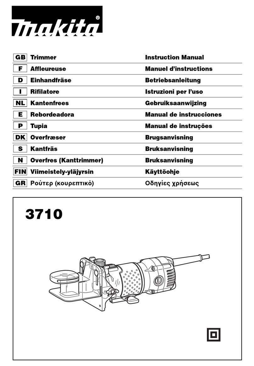
Referto the separateparts catalog for
decallocations, part numbers and
ordering instructions.
ForwardClutchControl
OperatingInstruction
ReverseClutchControl
_OperaUngInstruction
StartingStabilization
Messageonengine
WarningMessages
ontinehood
HotSurfaces
Warningonbeltcover
Figure1:LocationofSafetyandOperatingDecals(Model 644Hshown).
OperatingSymbols
Various symbols (shown here, with word
descript'_ns)are used on the tiller and engine
(your unit may not haveallof thesymbols).
FAST SLOW STOP
HI÷1
CHOKE CHOKE
ON OFF
(--411
TILLERDIRECTION
R
REVERSE ROTATING
TINES
(-- o--->
LEVERDIRECTION
BAIL
ENGAGED BAIL
DISENGAGED
TO AVOID SERIOUS INJURY:
READTHE OWNER'SMANUAL.
KNOWLOCATIONSANDFUNCTIONSOFALLCONTROLS.
KEEPALL SAFETYDEVICESAND SHIELDSIN PLACEANDWORKING.
NEVERALLOWCHILDRENOR UNINSTRUCTEDADULTSTO OPERATETILLER.
SHUTOFFENGINEANDDISCONNECTSPARKPLUGWIRE BEFOREMANUALLYUNCLOG-
GINGTINESORMAKINGREPAIRS.
KEEPBYSTANDERSAWAYFROMMACHINE.
KEEPAWAYFROM ROTATINGPARTS.
USEEXTREMECAUTIONWHENREVERSINGORPULLINGTHEMACHINETOWARDSYOU.
I]Assembly
WARNING
To prevent personal injury or
property damage, do not start
the engine until all assembly
steps are complete and you
have read and understand the
safety and operating instruc-
tions in this manual.
Introduction
Carefullyfollow theseassembly steps to
correctly prepareyour tiller for use, It is
recommendedthat you readthis Section
in its entirety before beginning assembly,
NOTE: Enginesylesvary by model, The
engineon your tiller may appeardiffer-
ently than those shown in illustrations
and Figuresthroughout this manual,
Inspect unit
Inspect the unit and carton for damage
immediately after delivery. Contactthe
carrier (trucking company) if you find or
suspect damage, Inform them of the
damageand request instructions for filing
aclaim. To protect your rights, put your
claim in writing and mail acopy to the
carrierwithin 15 daysafter theunit has
beendelivered,
STEP1: UnpackingInstructions
1. Removeanycardboard inserts and
packagingmaterial from the carton.
Removeany staplesfrom the bottom of
thecarton and then lift thecarton up and
off theunit.
2,Thetiller is heavyandyou should not
attempt to remove it from the shipping
platform until the handlebarsare
installed, Theprocedurefor removing the
tiller is explainedin Step3 of these
assemblysteps.
NOTE:Becareful not to severelybendany
of the control cableson the unit.
3. Removeall unassembledpartsand
the separatehardwarebag from the
carton, Checkthat you havethe items
listed below (contact your localdealer or
the factory if any items aremissing or
damaged), NOTE: Usethe screw length
template (Fig, 2-1) to identify screws,
LoosePartsList
Qty. Description
1 HandlebarSupport (seeA, Fig, 2-2,
page7)
1 HandlebarAssembly
(seeK, Fig,2-2)
Thefollowing itemsare in the
hardwarebag:
1 Slotted hd. screw, #10-24 x 2"
1 Hexhd, screw, 1/4-20 x 1-1/4"
6 Curvedhd. screw, 5/16-18 x 1-1/2"
2Hexhd, screw, 3/8-16 x 3/4"
2Flatwasher,3/8"
6 Split Iockwasher,5/16"
1 HexIocknut, 1/4"-20
6 Hexnut, 5/16"-18
2HexIocknut, 3/8"-16
1 Hexnut,#10-24
1 Spring, cable(seeW, Fig. 2-5,
page8)
1 Bracket,forward clutch cable (see
P,Fig, 2-5, page8)
1 Bracket,reverseclutch cable (see
BB,Fig, 2-8, page9).
IMPORTANT:Motoroil mustbeaddedto
the enginecrankcasebeforethe engine
isstarted. Followthe instructionsinthis
"Assembly"section.
NOTE:LEFTand RIGHTsides of the tiller
are asviewed from the operator's
position behindthe handlebars.
Tools]MaterialsNeededfor
Assembly
(1) 3/8" open-endwrench*
(2) 7/16" open-endwrench*
(1) l/2" open-endwrench*
(2) 9/16" open-endwrench*
(1) Large adjustablewrench
(1) Scissors (to trim plastic ties)
(1) Ruler (for belt tension check)
(1) Block of wood (to support tiller
whenremoving wheels)
(1) Automotive-type air pressure gauge
(1) Cleanoil funnel
(1) Clean,high-quality engine oil Refer
to the EngineOwnerManualfor
engineoil specifications andquantity
required, Do not overfill,
* Adjustablewrenches may be used.
Figure2-1: Toidentifylengthofscrew,
placescrewontemplateasshownand
measuredistancebetweenbottomofscrew
headandtipofscrew.
6
STEP2: Attach Handlebar
1. Attachthe two legs ofthe handlebar
support (A, Fig.2-2) loosely tothe inner
sides of the tiller frame using two 3/8"-16
x 3/4" hexhd. screws (B), 3/8" flat
washers(C) and 3/8"-16 hexIocknuts (D).
2. Using the middle holesin the handlebar
support brackets (Eand F,Fig. 2-2),
loosely attachthe support brackets to the
handlebarsupport (A) using two 5/16"-18
x 1-1/2" curved hd. screws (G),5/16" split
Iockwashers (H)and 5/16"-18 hexnuts (I).
NOTE:If a support bracketwill not move,
loosenattaching screw (J) and nut.
3. Attach the handlebarassembly (K) to
thehandlebarsupport (A) using four
5/16"-18 x 1-1/2" curved hd. screws (G),
5/16" split Iockwashers(H) and 5/16"-18
hexnuts (1).Tighten the four screws
securely.
4. Tighten all handlebarmounting
hardwaresecurely.
STEP3: MoveTiller OffShipping
Platform
Tomove the tiller withouttheengine
running, put the wheelsin their
FREEWHEELposition, asdescribed below.
1. Usea sturdy block to raiseonewheel
off theground.
2. Removethe hairpin cotter (L, Fig.2-3)
and wheeldrive pin (M). Slide the wheel
inward on the wheelshaft (N). Reinstall
thewheel drive pin and hairpin cotter
through the wheelshaft only (not through
thewheel hub). Repeatwith the other
wheel.
3. Using the handlebaras a lever, roll the
tiller to aflat area.
IMPORTANT:Beforestarting the engine,
thewheels must be placedin theirWHEEL
DRIVEposition (pins through wheel hubs
and wheelshaft). This procedureis
described in "Wheel Drive Pins" in
Section 3.
\B
C
D
Fig. 2-2: Attachhandlebar.
I
L
Fig. 2-3: Wheel in FREEWHEELING
position(wheel drivepin throughwheel
shaRonly).
Section2: Assembly
7
Section2: Assembly
STEP4: Install ForwardClutchCable
1. Placetheforward clutch cablebracket
(P,Fig. 2-4) on the handlebarsupport (A).
Attach thecable bracketusing a 1/4"-20 x
1-1/4" hexhd, screw (R, Fig. 2-4) and
1/4"-20 hexIocknut (S).Tighten securely.
2. Carefullyunwrap the forward clutch
cable (thecablewithout a knob attachedto
it) from its shipping position and slide the
thin cablewire (T, Fig. 2-4) into the slot in
thecablebracket. Pushthecableconnector
(U, Fig,2-4) up through the hole in the
bracket until the groove in the connector
snaps into placeon the bracket.
3. Insertthe #10-24 x 2" slotted hd. screw
(V,Fig. 2-5) down into the cablespring
(W). Thethreadedend of thescrew will
extend from the bottom of the spring.
4. Threadthe#10-24 hex nut (Z) on the
slottedheadscrew(V).Threadit halfwayup,
5. Threadscrew (V) intocableadjuster (X),
6. Hook cablespring (W, Fig. 2-6) into "V"-
shapedbend in theforward clutch bail (Y).
7. Lift and hold the ForwardClutch bail
against the handlebar.SeeFig, 2-7,
8. Measurethe length of the cablespring
betweenthe ends of the coils (Fig.2-7).
Thelength should be approximately 1-7/8".
If the length is correct, turn the #10-24 hex
nut (Z) down tightly againstthe cable
adjuster (X) while holding theadjuster in
place. SeeFigure2-7, If the length is
incorrect, you must makean adjustment to
the cabletension as described in
"Checking andAdjusting Forward Drive
Belt Tension"in Section 5. Whenthe
spring length is correct, tighten the hex nut
(Z)against the cableadjuster (X).
STEP5: Install ReverseClutch
Cable
1. Removethetwo pre-installedself-tapping
screws (AA,Fig, 2-8) from the handlebars.
2. Position the reversecablemounting
bracket (BB,Fig, 2-8) asshown and
reinstall thetwo self-tapping screws.
3. Unwrapthe reverseclutch cable (the
cablewith a knoband a large hex nut
attachedto it) from around its shipping
positionand routethe cable(CC,Fig.2-8
and Fig,2-9) up to thecable bracket(BB,
Fig, 2-8), Be surethat thecable goes
beneaththe ForwardClutch Bailas it is
routed up to the cablebracket.
8
R
Fig. 2-4: Installing forwardclutchcable bracketand cable.
W-- Fig.2-5:Assemble
springandadjuster.
V-- --Z
X--
Fig,2-6:Installforwardclutchcable,
Fig.2-7:Measurecablespring.
Section2: Assembly
4. Insertthe cableup through the slot in
the cablebracketand position the
threadedassembly asshown in Fig, 2-8,
Makesurethat the flat sideof the
threadedassembly is aligned with the fiat
side of the mounting hole, Slidethe large
hexnut (DD) up thecableand tighten it
securely,
5. Usea cabletie (EE,Fig,2-9) to fasten
the reverseclutch cableto the left side
handlebar,
6. Testthe function of the reverseclutch
cable by pulling the knob out and
releasingit. Theknob should return to its
neutralposition(resting against bracket)
when it is released. If it doesn't, contact
your localdealer or the factory for
technical assistance,
AA_ I
DD
FlatSide
Fig.2-8:Installreversecablemounting
bracketandthereverseclutchcable.
STEP6: CheckLevelof
TransmissionGearOil
Thetransmission was filled with gear oil
at the factory. However,you should check
the gear oil levelto make certain it is
correct.
IMPORTANT:Donot operatethe tiller if
the gear oil levelis low. Doingso will
result in severedamageto the transmis-
sion components,
1. Putthe tiller on level ground. Pull the
DepthRegulator Lever (FF,Fig. 2-10)
back and then adjust it up or down to the
notch that makesthe tiller level.
2. Removethe oil fill plug (GG,Fig, 2-11)
from the transmission housing and look
into theoil fill hole. You will seethe main
drive shaft on one sideof the hole,
3. The gearoil level is correct if the gear
oil is approximately halfwayup the side of
the drive shaft,
4. If the gear oil levelis low, add gear oil
by referring to "A. To Checkthe Transmis-
sion GearOil Level"in Section 5,
STEP7: Add Motor Oil to Engine
The tiller isshippedwithoutoil in the
engine.
IMPORTANT: Do not start the engine
without first adding motor oil.Severe
engine damagewill result if the engine is
run without oil,
1. Referto the EngineOwner's Manual
(suppliedwith tiller) for engine oilspecifi-
cations and capacities,
2. With the tiller on levelground, pullthe
DepthRegulator Lever (FF,Fig. 2-10)
back and then slide it up or downas
necessaryuntil theengine is level.
3. Add motor oil asdescribed in the
EngineOwner's Manual.
4. Move the Depth Regulator Leverall the
way down until the highest notch is
engaged, This placesthetines in the
"travel" position,
Fig, 2-10: AdjustDepthRegulator Lever.
Fig.2-11:Removegearoilfillplug.
STEP9: CheckAirPressurein
Tires)
Usea tire pressuregauge to checktheair
pressurein both tires, Deflateor inflate
both tires equallyto 15-to-20 PSI
(pounds per square inch), Be surethat
both tires areinflated equallyor the unit
will pullto one side.
IMPORTANT: This completes the
assembly steps, Beforeoperating your
tiller, make sureyou readthe following
Sectionsin this Manual, aswell as the
separateEngineOwner's Manual:
•Section 1: "Safety"
• Section 3: "Featuresand Controls"
• Section 4: "Operation"
Fig. 2-9: Routereverseclutchcable (CC)as
shown. Attachtohandlebarwith cable tie
(EE).
STEP8: CheckHardwarefor
Tightness
Checkall nuts and screws for tightness,
n
FeaturesandControls
WARNING
Before operating your
machine, carefully read and
understand all safety, controls
and operating instructions in
this Manual, the separate
Engine Owner's Manual, and
on the decals on the machine.
Failure to follow these
instructions can result in
serious personal injury.
Forward ReverseClutch
ClutchBail Control
ulator
ight
Adjustment Anti-ReverseStake
DrivePin
(on eachwheel)
Figure3-1: Featuresandcontrols.
Introduction
Thissectiondescribes thelocationsand
functions of thecontrols on your tiller.
Referto the next section ("Operation")
for detailedoperating instructions.
Practiceusing thesecontrols, with the
engine shut off, until you understand the
operationof the controls and feel
confident with eachof them,
IMPORTANT:Referto theseparate
engine manufacturer's EngineOwner's
Manualfor informationabout the
controls on theengine.
lO
WheelDrivePins
WARNING
Never allow either of the
wheels to be in the
FREEWHEEL position when
the engine is running. Always
put both wheels in the WHEEL
DRIVE position before starting
the engine.
Failure to comply could cause
loss of tiller control, property
damage, or personal injury.
Eachwheel isequippedwith aWheel
Drive Pin (A,Figures 3-2 and 3-3) that
securesthe wheelto the wheelshaft (B).
Thewheelscan be positioned in either a
WHEELDRIVEor a FREEWHEELmode.
Beforestarting the engine,put both
wheels inthe WHEELDRIVEposition by
inserting theWheel Drive Pinsthrough
the wheelhubs and thewheel shaft, This
"locks" thewheels to the wheel shaft,
causing the wheelsto turn when either
the ForwardClutch Bailor the Reverse
ClutchControl is engaged.
Usethe FREEWHEELmode only whenthe
engineis not running, In FREEWHEEL,
theWheel Drive Pinsare placedonly
through the holesin the wheel shaft (not
thewheel hubs), thus allowingthe wheels
to turn freely whenthe tiller is pushed or
pulled by hand,
To Place theWheelsin WHEELDRIVEor
FREEWHEEL:
1. Stop the engine,disconnect the spark
plug wire from the spark plug andallow
theengine to cool,
2. Raiseonewheeloff theground and
placea sturdy supportunder the
transmission.
3. Removethe wheeldrive pin (A,
WARNING
Do not place the tiller on its
side when changing the wheel
drive positions as doing so
could result in gasoline
leaking from the fuel tank.
Failure to follow this instruc-
tion could result in personal
injury or propertydamage.
Figures 3-2 and 3-3) byremoving the
hairpin cotter (C).