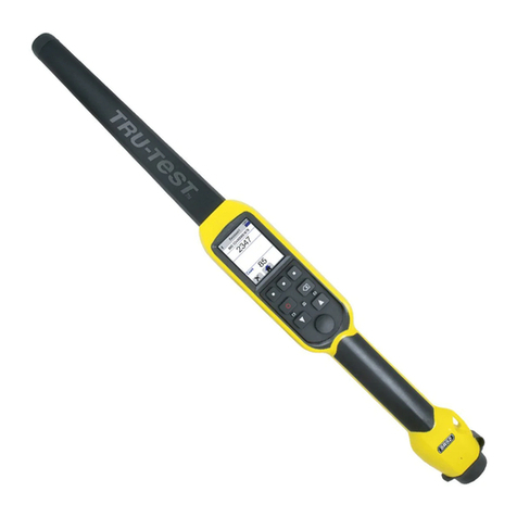
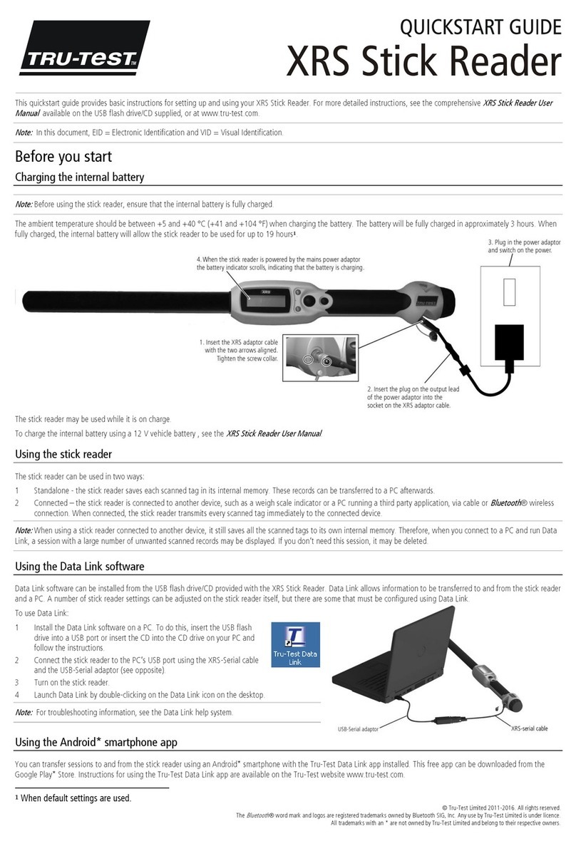
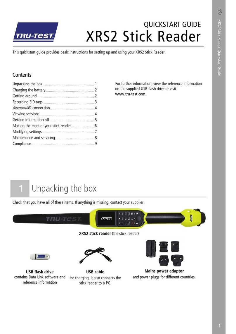
Tru-Test XRP2 User manual

1
QUICKSTART GUIDE
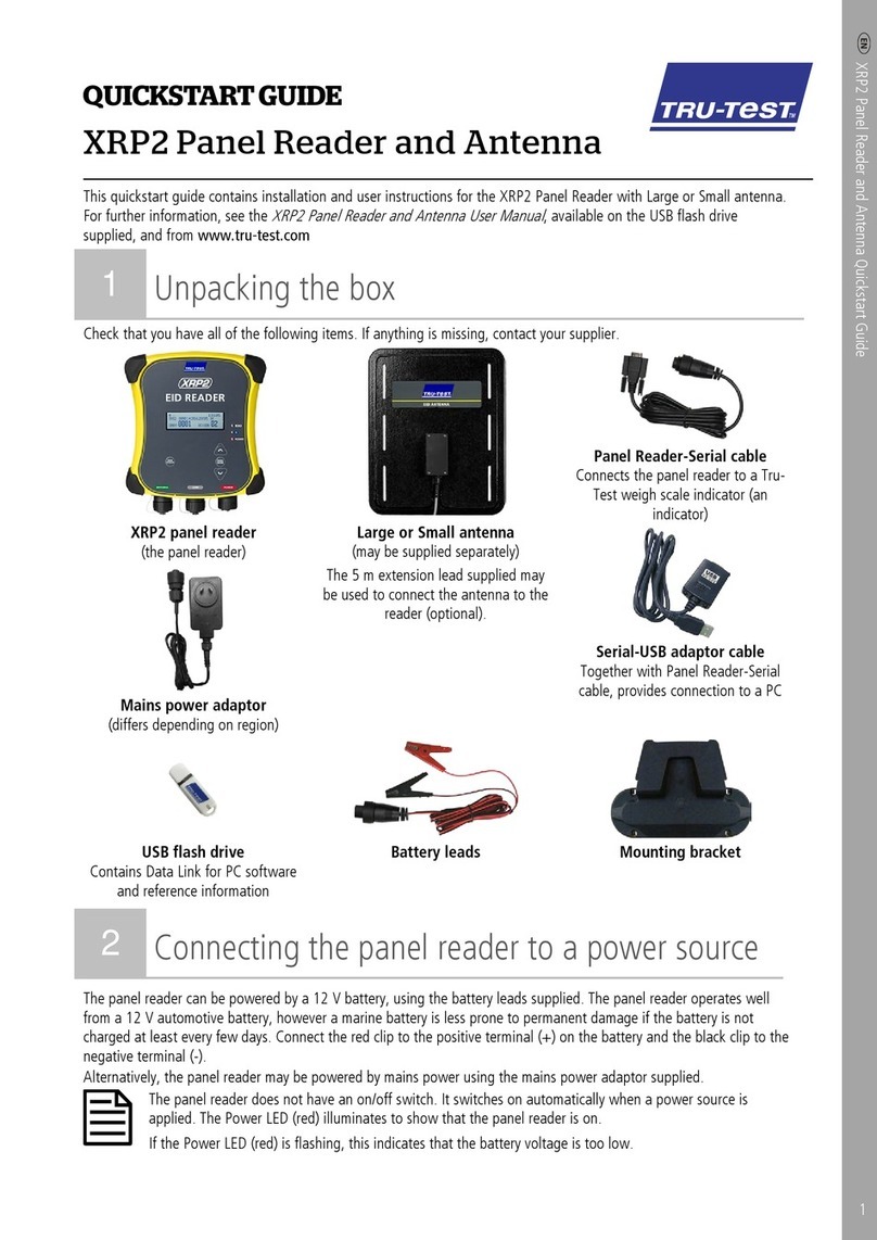
This quickstart guide contains installation and user instructions for the XRP2 Panel Reader with Large or Small antenna.
Contents
Unpacking the box................................................. 1
Connecting the panel reader to a power source ...... 2
Getting around ...................................................... 2
Ways to use the panel reader ................................. 3
Installing the panel reader and antenna.................. 3
Connecting to an indicator (optional)...................... 5
Recording EID tags................................................. 5
Getting information off........................................... 6
Modifying the panel reader settings........................ 6
Troubleshooting..................................................... 8
Further information ................................................ 9
Compliance.......................................................... 10
For further information, see the
XRP2 Panel Reader and
Antenna User Manual
, available on the USB flash drive
supplied, and from www.tru-test.com
1Unpacking the box
Check that you have all of these items. If anything is missing, contact your supplier.
XRP2 panel reader
(the panel reader)
Large or Small antenna
(may be supplied separately)
The 5 m extension lead supplied may be
used to connect the antenna to the reader
(optional).
Panel Reader-Serial cable
Connects the panel reader to a Tru-Test
weigh scale indicator (an indicator).
Serial-USB adaptor cable
Together with Panel Reader-Serial cable,
provides connection to a PC.
Mains power adaptor
(differs depending on region)
USB flash drive
Contains Data Link for PC software and
reference information.
Battery leads Mounting bracket

2
2Connecting the panel reader to a power source
The panel reader can be powered by a 12 V battery, using the battery leads supplied. The panel reader operates well from a 12 V
automotive battery, however a marine battery is less prone to permanent damage if the battery is not charged at least every few
days. Connect the red clip to the positive terminal (+) on the battery and the black clip to the negative terminal (-).
Alternatively, the panel reader may be powered by mains power using the mains power adaptor supplied.
The panel reader does not have an on/off switch. It switches on automatically when a power source is applied. The
Power LED (red) illuminates to show that the panel reader is on.
If the Power LED (red) is flashing, this indicates that the battery voltage is too low.
3Getting around
Parts of the panel reader
Parts of the panel reader's LCD

3
4Ways to use the panel reader
The panel reader can be used in two ways:
1. Standalone - the panel reader saves each scanned tag in its internal memory. These records can be transferred afterwards, as
described in
Section 8 – Getting information off.
2. Connected – the panel reader immediately transmits every scanned tag to a connected device, such as an indicator.
5Installing the panel reader and antenna
Example installation
In this example, a single panel reader is being used as part of a weighing system. The panel reader and antenna are mounted to
a cattle crush and the panel reader is connected to an indicator and load bars. When the animal enters the cattle crush, its EID tag
number is scanned by the panel reader and sent to the indicator.
XRP2 Panel Reader
Tru-TestAntenna
EIDTag
Tru-TestIndicator

4
Installation information
The panel reader and antenna can be mounted onto a flat surface (timber rails, concrete), or onto metal pipe-work, using the
hardware supplied. If you have a large antenna, the panel reader can also be mounted directly on the back of the antenna.
When mounting the antenna, do not damage it by drilling through it or piercing the surface with a screw. Use the
mounting holes provided.
Factors to consider:
•The panel reader and antenna should be installed on the outside of a crush/chute, weigh crate or drafter so that it is not
damaged by animal movement.
•Animal flow must be restricted to ensure that only one animal is within the antenna’s read range.
•The location of the antenna in relation to metal bars or pipes needs to be considered. See the diagram in
Section 10 -
Troubleshooting
.
•The positioning of the antenna is important to obtain an effective read of the EID tag:
Antenna
Front of crush/chute,
weigh crate or drafter Read zone
Animal flow inside
crush/chute, weigh
crate or drafter
Keep animals
out of this area.
Animals inside
this area could
adversely affect
read performance
and may damage
the antenna
Antenna
After you have installed the antenna and reader, connect the antenna to the panel reader. An extension lead may be required
(supplied with the antenna).
Two antennas may be used, or the panel reader may be synchronised and used with another panel reader. For more
information, see the
XRP2 Panel Reader and Antenna User Manual.

5
6Connecting to an indicator (optional)
Connecting to a
Bluetooth
®enabled indicator
To establish a
Bluetooth
wireless connection between the panel reader and a Tru-Test
Bluetooth
enabled indicator, you need to
‘pair’ the two devices. The panel reader can be paired with any Tru-Test
Bluetooth
enabled indicator and to some third party
devices.
When connecting the panel reader wirelessly to a Tru-Test indicator, always turn the indicator on BEFORE the panel
reader.
1. With both devices off, position the panel reader within 5 metres of the indicator.
2. Switch on the indicator and, if necessary, check that its
Bluetooth
setting is enabled.
3. Connect the panel reader to a power source (battery or mains power).
Wait for up to 1 minute until the two devices are paired. When pairing is complete, the panel reader’s
Bluetooth
wireless connection LED (blue) illuminates and the LCD displays the name of the connected
device.
4. Use the panel reader to scan an EID tag in order to test the connection.
Connecting to an indicator that does not offer
Bluetooth
wireless connectivity
Connect the panel reader to the indicator using the Panel Reader-Serial cable supplied. Follow the instructions provided with your
indicator.
7Recording EID tags
The method used to record EID tags differs depending on whether the panel reader is being used ‘standalone’ or ‘connected’ (to
another device such as an indicator). For more information, see
Section 4 – Ways to use the panel reade
r.
Recording EID tags when the panel reader is connected to another device
Refer to example installation diagram in
Section 5 – Installing the panel reader and antenna
.
1. Set up the indicator or other device for a recording session, according to the instructions provided with the device.
2. Move the animal into the cattle crush.
When the animal passes near the antenna, the EID tag will be read by the panel reader and sent to the connected indicator.
The EID tag is recorded in the indicator’s internal memory. The EID tag number will appear on the panel reader’s LCD, the
Read LED (green) will flash and the panel reader will beep to indicate that the tag has been read successfully.
Recording EID tags when the panel reader is being used on its own (standalone)
1. Start a new recording session by pressing . The panel reader beeps and the session number appears on the LCD.
2. Move the animal into the cattle crush.
When the animal passes near the antenna, the EID tag will be read and recorded in the panel reader’s internal memory. The
EID tag number will appear on the panel reader’s LCD, the Read LED (green) will flash and the panel reader will beep to
indicate that the tag has been read successfully.

6
8Getting information off
There are two ways to get information off the panel reader.
Data Link for PC Data Link app for Android* smartphone
You can:
•save session files
•
register a transaction with NAIT or NLIS (New Zealand and
Australia only).
•transfer session files to MiHub Livestock.
You can:
•transfer and share session files
•register a transaction with NAIT or NLIS (New Zealand and
Australia only).
•transfer session files to MiHub Livestock
To do this:
1. Connect the panel reader to a PC using the cable supplied.
2. Launch Data Link on your PC.
3. Click to get information off the panel reader.
To do this:
Launch the app on your smartphone and follow the instructions.
The Tru-
Test Data Link app is available to download for
free from the Google Play* store (Android* devices).
9Modifying the panel reader settings
Accessing panel reader settings
To access the panel reader settings:
Press .
The first three items appear on the LCD.
To scroll through and highlight options, press or repeatedly.
To select a highlighted option, press .
To exit out of the panel reader settings, highlight EXIT, then press .

7
Panel reader settings
Menu name
Options
Description
BLUETOOTH® Auto** The panel reader will automatically connect to previously used devices or other
Tru-Test devices.
Manual This setting should be used when connecting to an Android* smartphone
Off Disables the
Bluetooth
wireless connection.
FIND BT DEVICES Allows you to manually search for other
Bluetooth
enabled devices.
PAIRED DEVICES Lists previously paired devices. Select from this list to connect to another device.
DUPLICATES On** The panel reader
will not
record the same EID twice in the same session.
Off The panel reader
will
record the same EID twice in the same session.
OUTPUT MODE Single** The panel reader will only record and send the same EID
once
.
Cont (Continuous) The panel reader will record only once but send the same EID
each time it is read
.
DATA FORMAT Data format changes the way that EIDs are stored and output from the panel
reader.
Dec 1 (Decimal 1)** Standard decimal format with a space between the country (or a manufacturer's,
possibly shared) code and the national identification (or a manufacturer's unique
within series) code e.g. 826 123456789012.
Dec 2 (Decimal 2) Decimal format used in some countries with no space between the country (or a
manufacturer's, possibly shared) code and the national identification (or a
manufacturer's unique within series) code e.g. 826123456789012.
Hex (Hexadecimal) e.g. 8000F58000000001.
ISO Complies with ISO 24631-6 e.g. 1000000826000000123456.
DIAGNOSTICS There are four diagnostics screens which provide troubleshooting information.
Select NEXT to scroll through the screens. If the values fall outside the normal
range, see
Section 10 - Troubleshooting.
Supply voltage The power supply voltage is displayed and should be followed by (OK).
Antenna voltage and
tuning value
The antenna voltage is displayed and should be followed by (OK). The tuning
value is displayed. The graph should show a dot in the middle band and be
followed by (OK).
Noise level Displays the levels of interference being detected. The noise level should be in the
lower part of the graph.
Read rate Displays the reads per minute for the current location of the tag.
SOFTWARE VERSION The panel reader software version.
LANGUAGE ENGLISH
ESPAÑOL
PORTUGUÊS
FRANÇAIS
DEUTSCH
You can change the language displayed on the panel reader’s LCD.
Default settings marked **

8
10
Troubleshooting

9
11
Further information
Caring for the panel reader and antenna
Do not immerse the panel reader or antenna in water. Store the panel reader in a cool, dry place.
Wipe the panel reader and antenna clean using a damp cloth, warm water and soap. Other cleaners may damage the equipment.
Do not leave the panel reader where it may be exposed to extreme temperatures (e.g. on the dashboard of a vehicle).
Fit the dust caps when there are no cables connected to the panel reader or antenna. This will prevent moisture and dirt from
entering the connectors.
Service and warranty information
For service and warranty information, see www.tru-test.com
More information
For further details, refer to the
XRP2 Panel Reader and Antenna User Manual
, available on the USB flash drive supplied and at
www.tru-test.com
Upgrading the software
To upgrade the panel reader’s software, use Data Link for PC:
1. Connect the panel reader to a PC using the Panel Reader-Serial cable and the Serial-USB adaptor cable supplied.
2. Launch the Data Link application.
3. Wait for the panel reader to connect to the PC (this may take up to a minute).
4. Click Tools / Updates and follow the instructions.
Europe - Instructions for disposal of product
This symbol on the product or its packaging indicates that this product (and its battery) must not be disposed of with
other waste. Instead, it is your responsibility to dispose of your waste equipment by handing it over to a designated
collection point for the recycling of waste electrical and electronic equipment. The separate collection and recycling of
your waste equipment at the time of disposal will help conserve natural resources and ensure that it is recycled in a
manner that protects human health and the environment. For more information about where you can drop off your
waste equipment for recycling, please contact your local city recycling office or the dealer from whom you purchased the
product.
This product incorporates a lithium metal (CR1220 35 mAh) button/coin cell battery.
For instructions on how to dismantle this product for recycling, email contact@trutest.co.nz

10
12
Compliance
FCC notice
This device complies with part 15 of the FCC Rules. Operation is subject to the following two conditions: (1) This device may not cause harmful interference, and (2) this device must accept any interference
received, including interference that may cause undesired operation.
This equipment has been tested and found to comply with the limits for a Class B digital device, pursuant to part 15 of the FCC Rules. These limits are designed to provide reasonable protection against
harmful interference in a residential installation.
This equipment generates, uses and can radiate radio frequency energy and, if not installed and used in accordance with the instructions, may cause harmful interference to radio communications.
However, there is no guarantee that interference will not occur in a particular installation. If this equipment does cause harmful interference to radio or television reception, which can be determined by
turning the equipment off and on, the user is encouraged to try to correct the interference by one or more of the following measures:
- Reorient or relocate the receiving antenna.
- Increase the separation between the equipment and receiver.
- Connect the equipment into an outlet on a circuit different from that to which the receiver is connected.
- Consult the dealer or an experienced radio/ TV technician for help.
- Any changes or modifications not expressly approved by Datamars could void the user's authority to operate the equipment
FCC warning
Note: Users are cautioned that changes or modifications not expressly approved by the party responsible for compliance could void the user’s authority to operate the equipment.
The XRP2 Panel Reader supplied (Tru-Test XRP2-1 Low Frequency Electronic ID (EID) Reader) has been approved for use only with approved external antennas described in this manual; use of any other
antenna may void the user’s authority to operate the equipment. This device and its antenna(s) must not be cohabited or operate in conjunction with any other antenna(s) or transmitter(s).
Responsible party in the USA
This product is supplied by:
Datamars Inc
528 Grant Road
Mineral Wells
Texas 76067
UNITED STATES
Toll free: 800 874 8494
Industry Canada notice
This radio transmitter, the XRP2 Panel Reader (Tru-Test XRP2-1 Low Frequency Electronic ID (EID) Reader) , has been approved by Industry Canada to operate with the antenna types listed below, with the
maximum permissible gain and required antenna impedance for each antenna type indicated. Antenna types not included in this list, having a gain greater than the maximum gain indicated for that type,
are strictly prohibited for use with this device.
•Large EID Antenna, for use with Tru-Test XRP2 Panel Reader – Gain (0 dBi), Impedance (2 kΩ)
•Small EID Antenna, for use with Tru-Test XRP2 Panel Reader – Gain (0 dBi), Impedance (2 kΩ)
Under Industry Canada regulations, this radio transmitter may only operate using an antenna of a type and maximum (or lesser) gain approved for the transmitter by Industry Canada.
This device complies with Industry Canada licence-exempt RSS standard(s). Operation is subject to the following two conditions: (1) this device may not cause interference, and (2) this device must accept
any interference, including interference that may cause undesired operation of the device.
Industry Canada warning
Installation within Canada: To maintain compliance with Industry Canada RF exposure compliance requirements, please follow the operation instructions as documented in this manual. This equipment
should be installed and operated with a minimum distance of 20 cm (8") between the antenna within this device and your body.
EU declaration of conformity
Datamars Limited hereby declares that this EID Reader, when used with both the Large and Small antennas described in this manual, is in compliance with the essential requirements and
other relevant provisions of Directive 2014/53/EU. The declaration of conformity may be consulted at http://livestock.tru-test.com/en/compliance
The
Bluetooth
®word mark and logos are registered trademarks owned by Bluetooth SIG, Inc. and any use of such marks by Datamars SA and its subsidiaries is under license. Other trademarks and trade
names are those of their respective holders.
All trademarks with an * are neither owned by nor licensed to Datamars SA and belong to their respective owners.

11
Esta guía de inicio rápido contiene instrucciones para la instalación y el uso del lector de panel XRP2 con antena grande o
pequeña.
Índice
Instrucciones de desempacado ............................. 11
Conexión del lector de panel a una fuente de
alimentación........................................................ 12
Vistazo general .................................................... 12
Maneras de usar el lector de panel ....................... 13
Instalación del lector de panel y de la antena........ 13
Conexión a un indicador (opcional)....................... 14
Registro de etiquetas IDE ..................................... 15
Transferencia de datos ......................................... 15
Modificación de los ajustes del lector de panel...... 16
Solución de problemas ......................................... 17
Mayor información............................................... 18
Cumplimiento normativo...................................... 18
Para obtener más información, consulte el
Manual de
usuario del lector de panel XRP2 y la antena
, disponible en
la unidad flash USB suministrada o en www.tru-test.com
1Instrucciones de desempacado
Revise que cuente con todos estos artículos. Si falta algo, póngase en contacto con su proveedor.
Lector de panel XRP2
(el lector de panel)
Antena grande o pequeña
(puede suministrarse por separado)
El cable de extensión, de 5 metros de longitud,
puede usarse para conectar la antena al lector
(opcional).
Cables de la batería
Cable serial del lector de panel
Conecta el lector de panel a un indicador de pesaje de
Tru-Test (el indicador).
Cable adaptador serial a USB
Proporciona, junto con el cable serial del lector de
panel, la conexión a una computadora.
Adaptador de alimentación eléctrica
(varía dependiendo de la región)
La unidad flash USB
Contiene el software Data Link para PC y la
información de referencia.
Soporte de montaje
GUÍA DE INICIO RÁPIDO

12
2Conexión del lector de panel a una fuente
de alimentación
El lector de panel puede alimentarse por una batería de 12 V mediante los cables de la batería suministrados. El lector de panel
funciona bien con una batería automotriz de 12 V, aunque una batería marina es menos propensa a sufrir daños permanentes si
no se carga por lo menos cada pocos días. Conecte el borne rojo al terminal positivo (+) de la batería y el borne negro al terminal
negativo (-).
Alternativamente, el lector de panel puede alimentarse por la red eléctrica mediante el adaptador de alimentación suministrado.
El lector de panel no tiene ningún interruptor de encendido y apagado. Se enciende automáticamente tras la conexión
a una fuente de alimentación. El LED de alimentación (rojo) se ilumina para mostrar que el lector de panel está
encendido.
Si el LED de alimentación (rojo) está parpadeando, esto indica que la tensión de la batería es demasiado baja.
3Vistazo general
Partes del lector de panel
Partes de la pantalla LCD del lector de panel

13
Cambio del idioma
¿Cómo cambiar el idioma en el lector de panel?
1. Pulse
2. Pulse
3. Pulse hasta visualizar su idioma.
4. Pulse para resaltar SALIR.
5. Pulse .
↓
4Maneras de usar el lector de panel
El lector de panel puede usarse de dos maneras:
1. Modo independiente: El lector de panel guarda cada etiqueta escaneada en su memoria interna. Estos registros pueden
transferirse posteriormente, como se describe en la
Sección 8 – Transferencia de datos del dispositivo
.
2. Modo conectado: El lector de panel transmite inmediatamente cada etiqueta escaneada a un dispositivo conectado, p.ej. a un
indicador.
5Instalación del lector de panel y de la antena
Ejemplo de instalación
En este ejemplo se usa un único lector de panel como parte
de un sistema de pesaje. El lector de panel y la antena están
montados en un cajón para vacuno y el lector de panel está
conectado a un indicador y barras de carga. Cuando el
animal entra en el cajón, el lector de panel escanea el
número de su etiqueta de identificación electrónica y lo
envía al indicador.
Información de instalación
El lector de panel y la antena pueden montarse en una
superficie plana (barras de madera o placa de hormigón) o
en tubos metálicos mediante el material de fijación
suministrado. Si tiene una antena grande, el lector de panel puede montarse también directamente en la parte trasera de la
antena.
Al montar la antena, tenga cuidado de no dañarla con el taladro o abrirle un agujero a la superficie con un tornillo.
Use los agujeros incluidos.
Factores que deben considerarse:
•El lector de panel y la antena deberían instalarse en la parte exterior del brete o cajón, una jaula o un sistema de clasificación
de manera que no puedan sufrir daños debidos al movimiento de los animales.
•El paso de los animales debe limitarse para asegurar que sólo un animal se encuentre dentro del alcance de lectura de la
antena.
•Se debe considerar la ubicación de la antena respecto a las barras o los tubos de metal. Véase el diagrama en la
Sección
10:Solución de problemas
.
•El posicionamiento de la antena es importante a fin de obtener una buena lectura de la etiqueta de identificación electrónica:
Lector de panel XRP2
AntenaTru-Test
Etiqueta de
identificación
electrónica (IDE)
IndicadorTru-Test

14
Antena
Parte frontal del brete,
de la jaula o del sistema
de clasificación Alcance de lectura
Paso de animales
dentro del brete, de la
jaula o del sistema
de clasificación
Mantenga los animales
fuera de este área.
Los animales que se
encuentran dentro
de este áreapodrián
afectar negativamente
la función de lectura y
ocasionardaños en la
antena.
Antena
Tras la instalación de la antena y del lector, conecte la antena al lector de panel. Puede requerirse un cable de extensión
(suministrado junto con la antena).
Pueden usarse dos antenas o el lector de panel puede sincronizarse y usarse con otro lector de panel. Para obtener
más información, véase el
Manual de usuario del lector de panel XRP2 y la antena
.
6Conexión a un indicador (opcional)
Conexión a un indicador habilitado para
Bluetooth
®
Para establecer una conexión inalámbrica
Bluetooth
entre el lector de panel y un indicador Tru-Test habilitado para
Bluetooth
, los
dos dispositivos deberán sincronizarse. El lector de panel puede sincronizarse con cualquier indicador Tru-Test habilitado para
Bluetooth
y con algunos dispositivos de otros fabricantes.
Cuando conecte el lector de panel de manera inalámbrica a un indicador Tru-Test, encienda el indicador siempre
ANTES que el lector de panel.
1. Con los dos dispositivos apagados, posicione el lector de panel a una distancia inferior a 5 metros del
indicador.
2. Encienda el indicador y, si es necesario, revise que está activada la función
Bluetooth
.
3. Conecte el lector de panel a una fuente de alimentación (batería o red eléctrica).
Espere hasta 1 minuto para que los dos dispositivos se sincronicen. Tras completar la sincronización,
se iluminará el LED (azul) de la conexión inalámbrica
Bluetooth
del lector de panel y la pantalla LCD
indicará el nombre del dispositivo conectado.
4. Use el lector de panel para escanear una etiqueta de identificación electrónica IDE a fin de comprobar
la conexión.
Conexión a un indicador sin conectividad inalámbrica
Bluetooth
Conecte el lector de panel al indicador mediante el cable serial suministrado del lector de panel. Siga las instrucciones facilitadas
junto con su indicador.

15
7Registro de etiquetas IDE
El método usado para registrar etiquetas de identificación electrónica varía dependiendo de si el lector de panel se usa en el
“modo independiente” o en el “modo conectado” (a otro dispositivo, p. ej. a un indicador). Para obtener más información, véase
la
Sección 4: Maneras de usar el lector de panel
.
Registro de las etiquetas de identificación electrónica cuando el lector de panel se conecta a otro
dispositivo
Consulte el diagrama del ejemplo de instalación en la
Sección 5: Instalación del lector de panel y de la antena
.
1. Configure el indicador u otro dispositivo para una sesión de registro conforme a las instrucciones del dispositivo.
2. Suba el animal al cajón para vacunos.
Cuando el animal pasa cerca de la antena, el lector de panel escanea el número de su etiqueta de identificación electrónica
y lo envía al indicador conectado. La etiqueta IDE se registra en la memoria interna del indicador. El número de la etiqueta de
identificación electrónica aparecerá en la pantalla LCD del lector de panel, el LED de lectura (verde) parpadeará y el lector de
panel emitirá una señal acústica para indicar la lectura correcta de la etiqueta.
Registro de las etiquetas de identificación electrónica cuando el indicador de panel se usa en el
modo independiente
1. Inicie una nueva sesión de registro pulsando . El lector de panel emitirá una señal acústica y el número de la sesión
aparecerá en la pantalla LCD.
2. Suba el animal al cajón para vacunos.
Cuando el animal pasa cerca de la antena, el lector de panel leerá y registrará la etiqueta en su memoria interna. El número
de la etiqueta de identificación electrónica aparecerá en la pantalla LCD del lector de panel, el LED de lectura (verde)
parpadeará y el lector de panel emitirá una señal acústica para indicar la lectura correcta de la etiqueta.
8Transferencia de datos
Existen dos maneras de transferir datos del lector de panel.
Data Link para PC Aplicación Data Link para teléfonos Android*
Ud. puede:
•guardar archivos de sesión
•registrar una transacción con SNIG (solo en Uruguay).
•transferir archivos de sesión a MiHub Livestock.
Ud. puede:
•transferir y compartir archivos de sesión
•registrar una transacción con SNIG (solo en Uruguay).
•transferir archivos de sesión a MiHub Livestock.
Para hacer esto:
1. Conecte el lector de panel a la PC a través del cabl
e USB
suministrado.
2. Abra la aplicación Data Link en su PC.
3. Haga clic en para transferir datos del lector de
panel.
Para hacer esto:
Ejecute la aplicación en su teléfono inteligente y siga las
instrucciones.
La aplicación Tru-Test Data Link está disponible para
descargar gratis en la tienda Google Play* (para
dispositivos Android*).

16
9Modificación de los ajustes del lector de panel
Cómo acceder a los ajustes del lector de panel
Para acceder a los ajustes del lector de panel:
Pulse .
Los tres primeros ajustes aparecen en la pantalla LCD.
Para desplazarse por las opciones y resaltarlas, pulse orepetidas veces.
Para seleccionar una opción resaltada, pulse .
Para salir de los ajustes del lector de panel, resalte SALIR y, a continuación, pulse .
Ajustes del lector de panel
Nombre del menú
Opciones
Descripción
BLUETOOTH® Auto** El lector de panel se conectará automáticamente a dispositivos previamente usados o a otros dispositivos de
Tru-Test.
Manual Debe usarse este ajuste para conectarse a un teléfono inteligente Android*
Apagado Desactiva la conexión inalámbrica
Bluetooth
.
BUSCAR DISPOS BT Le permite buscar manualmente otros dispositivos habilitados para
Bluetooth
.
DISPOS SINCRONIZ Ofrece una lista de los dispositivos previamente sincronizados. Seleccione una opción de esta lista para conectarse a otro dispositivo.
DUPLICADOS Enc (Encendido)** El lector de panel
no registrará
dos veces el mismo número de identificación electrónica (IDE) en la misma
sesión.
Apagado El lector de panel
registrará
dos veces el mismo número de identificación electrónica (IDE) en la misma sesión.
MODO SALIDA Único** El lector de panel registrará y enviará sólo
una vez
el mismo número de identificación electrónica (IDE).
Contin (Continuo) El lector de panel registrará el mismo número de identificación electrónica (IDE) sólo una vez y lo enviará
cada
vez que se lee
.
FORMATO DATOS El formato de datos cambia la manera en que se guardan y se muestran los números de las etiquetas de identificación electrónica (IDE)
del lector de panel.
Dec 1 (Decimal 1)** Formato decimal estándar con un espacio entre el código del país (o del fabricante, posiblemente compartido)
y el número de identificación nacional (o un código único del fabricante en caso de diferentes series), p. ej.
826 123456789012. 123456789012.
Dec 2 (Decimal 2) Formato decimal usado en algunos países sin ningún espacio entre el código del país (o del fabricante,
posiblemente compartido) y el número de identificación nacional (o un código único del fabricante si se trata de
la misma serie), p. ej. 826123456789012.
Hex (Hexadecimal) P. ej. 8000F58000000001.
ISO Cumple con la norma ISO 24631-6, p. ej. 1000000826000000123456.
DIAGNÓSTICO Existen cuatro pantallas de diagnóstico que brindan información para resolver problemas. Seleccione SIG. (SIGUIENTE) para desplazarse
por las pantallas. Si los valores quedan fuera del rango normal, véase la
Sección 10: Resolución de problemas
.
Tensión alimentac
(Tensión de
alimentación)
Se indica la tensión de alimentación seguida por (OK).
Tensión de antena y
valor sintoni (Valor de
sintonización)
Se visualiza la tensión de la antena seguida por (OK). Se indica el valor de sintonización. El gráfico debería
mostrar un punto en la franja media seguido por (OK).
Nivel de ruido Indica los niveles de interferencia detectados. El nivel de ruido debería situarse en la parte baja del gráfico.
Indice de lectura Indica las lecturas por minuto de la ubicación actual de la etiqueta.
VER SW (VERSIÓN DE SOFTWARE) Indica la versión de software del lector de panel.
IDIOMA ENGLISH
ESPAÑOL
PORTUGUÊS
FRANÇAIS
DEUTSCH
Se puede modificar el idioma visualizado en la pantalla LCD del lector de panel.
Las opciones predeterminadas están marcadas con un **

17
10
Solución de problemas

18
11
Mayor información
Cuidado del lector de panel y de la antena
No sumerja el lector de panel o la antena en agua. Guarde el lector de panel en un lugar fresco y seco.
Limpie el lector de panel y la antena con un paño húmedo, agua templada y jabón. Otros detergentes pueden dañar el equipo.
No deje el lector de panel en lugares donde pueda quedar expuesto a temperaturas extremas, p. ej. en el tablero de un vehículo.
Coloque los tapones protectores cuando no haya cables conectados al lector de panel o la antena. De esta manera protegerá los
conectores de la humedad y el sucio.
Información sobre la garantía y el servicio
Para mayor información sobre la garantía y el servicio, visite www.tru-test.com
Más información
Para obtener más información, consulte el
Manual de usuario del lector de panel XRP2 y la antena
, disponible en la unidad flash
USB suministrada o en www.tru-test.com
Actualización del software
Para actualizar el software del lector de panel, utilice Data Link para PC:
1. Conecte el lector de panel a una computadora mediante el cable serial del lector de panel y el cable adaptador serial a USB
suministrados.
2. Abra la aplicación Data Link.
3. Espere hasta que el lector de panel se conecte a la computadora (esto puede tardar hasta un minuto).
4. Haga clic en Herramientas / Actualizaciones y siga las instrucciones.
Europa - Instrucciones para la eliminación del producto
Este
símbolo en el producto o en el embalaje indica que no se puede desechar el producto (y su batería) junto con los
residuos domésticos. Es responsabilidad del usuario desechar del aparato entregándolo en un punto destinado al
reciclaje de residuos de aparatos eléctricos y electrónicos. La recolección y el reciclaje por separado de sus residuos en
el momento en el que Ud. se deshace de los mismos ayudarán a preservar los recursos naturales y a garantizar que el
reciclaje se realice de modo inocuo para la salud de las personas y el medio ambiente. Si desea obtener mayor
información sobre los puntos de reciclaje de residuos de aparatos, póngase en contacto con las autoridades locales de
su ciudad, el servicio de eliminación de residuos domésticos o la tienda donde adquirió el producto.
Este producto incorpora una batería de botón de metal de litio (CR1220 35 mAh).
Si desea recibir instrucciones para desarmar este producto para su reciclado, escríbanos a [email protected].nz
12
Cumplimiento normativo
Declaración de la UE de conformidad
Datamars Limited declara por la presente que este lector de identificación electrónica, usado junto con las antenas grandes o pequeñas descritas en este manual, cumple con los requisitos
fundamentales además de otras disposiciones relevantes de la directiva 2014/53/UE. La declaración de conformidad puede consultarse en http://livestock.tru-test.com/en/compliance
La marca
Bluetooth
®y sus logotipos son marcas registradas de Bluetooth SIG, Inc. y el uso por parte de Datamars SA o cualquiera de sus dependencias se hace bajo licencia. Las otras marcas y nombres
comerciales pertenecen a sus respectivos propietarios.
Todas las marcas registradas con un * no son propiedad de Datamars SA ni se cuenta con una licencia, y pertenecen a sus respectivos dueños.

19
MANUAL BÁSICO
O presente guia rápido contém instruções de instalação e do utilizador para o leitor de painel XRP2 com uma antena grande ou
pequena.
Conteúdo
Desembalar a caixa.............................................. 19
Conetar o leitor de painel a uma fonte de energia 20
Conhecer o aparelho............................................ 20
Como usar o leitor de painel................................. 21
Instalação do leitor de painel e da antena............. 21
Conexão com um indicador (opcional) .................. 22
Registrar brincos IDE ............................................ 23
Transferir informações.......................................... 23
Modificar os ajustes do leitor de painel................. 24
Solução de falhas................................................. 25
Informações suplementares.................................. 26
Conformidade...................................................... 26
Para informações mais detalhadas consulte o
Manual do
Usuário do Leitor de Painel XRP2 com Antena
, disponível na
unidade flash USB fornecida e na www.tru-test.com
1Desembalar a caixa
Verifique que haja todos os seguintes itens. Se algo estiver faltando, contate o seu fornecedor.
Leitor de painel XRP2
(o leitor de painel)
Antena grande ou pequena
(é possível que seja fornecida à parte)
O cabo de extensão de 5 m fornecido pode ser
usado para conetar a antena ao leitor (opcional).
Cabos da bateria
Cabo serial do leitor de painel
Coneta o leitor de painel a um indicador de pesagem
da Tru-Test (um indicador).
Adaptador de cabo serial USB
Permite a conexão a um PC, junto com o cabo serial do
leitor de painel.
Adaptador de alimentação de rede
(difere, dependendo da região)
Unidade flash USB
Contém o software Data Link para PC e
informações de referência.
Grampo de montagem

20
2Conetar o leitor de painel a uma fonte de energia
O leitor de painel pode ser alimentado por uma bateria 12 V, usando os cabos de bateria fornecidos. O leitor de painel opera bem
com uma bateria automotiva 12 V, mas uma bateria marinha é mais resistente contra danificação permanente, se a bateria não
for carregada pelo menos de poucos em poucos dias. Fixe o clip vermelho no terminal positivo (+) da bateria e o clip preto no
terminal negativo (-).
Alternativamente, o leitor de painel pode ser alimentado pela rede, usando o adaptador de alimentação de rede fornecido.
O leitor de painel não tem um interruptor para ligar/desligar. Ele liga-se automaticamente, quando uma fonte de
energia é conetada. O LED de energia (vermelho) acende-se para mostrar que o leitor de painel está ligado.
O LED de energia (vermelho) pisca para indicar que a tensão da bateria é fraca.
3Conhecer o aparelho
Partes do leitor de painel
Partes do LCD do leitor de painel
Other manuals for XRP2
3
Table of contents
Languages:
Other Tru-Test Card Reader manuals
Popular Card Reader manuals by other brands

DÖRR
DÖRR DR SuperSpeed USB 3.0 instruction manual
Rosslare
Rosslare CSN SELECT AYC-6355 Series Installation and user manual
Allegion
Allegion Schlage SMR-10 Installation and maintenance instructions
iZettle
iZettle Lite Getting started
IDTECK
IDTECK Star RFK101 Quick installation guide
Sitecom
Sitecom PRO LINE MD-1009 user manual
