Tru-Test Unigizer 12000i User manual

1
ENGLISH.......................................................................... 1
SVENSKA ...................................................................... 14
NEDERLANDS................................................................ 25
DANSK .......................................................................... 37
WARRANTY................................................................... 50
TEMPLATES................................................................... 51
© 2008-2015 Tru-Test Limited
All product names and brand names in this document are trademarks or registered trademarks of their
respective holders.
No part of this publication may be photocopied, reproduced, stored in a retrieval system, or transmitted in
any form or by any means, electronic, mechanical, photocopying, recording or otherwise without the prior
written permission of Tru-Test Limited. Product specifications may change without prior notice.
For more information on other quality Tru-Test Group brands and products, visit www.tru-test.com.
Tru-Test Limited
25 Carbine Road
Mt Wellington
Auckland 1060
New Zealand
Postal address:
P O Box 51078
Pakuranga
Auckland 2140
New Zealand
Tru-Test Ltd thanks the International Electrotechnical Commission (IEC) for permission to reproduce
Information from its International Publication 60335-2-76 ed.2.2(2013). All such extracts are copyright of
IEC, Geneva, Switzerland. All rights reserved. Further information on the IEC is available from www.iec.ch.
IEC has no responsibility for the placement and context in which the extracts and contents are reproduced
by the author, nor is IEC in any way responsible for the other content or accuracy therein.
829767 Issue 1 (to be supplied to Continental Europe [only] with 816260) 08/2015
ENGLISH
Electric fencing and your energizer
Congratulations on the purchase of your energizer. This product has
been constructed using the latest technology and construction
techniques. It has been engineered to give superior performance and
many years of service.
It is important to read these instructions carefully and thoroughly. They
contain important safety information and will assist you in ensuring that
your electric fencing system gives maximum performance and reliability.
How does an electric fence work?
An electric fence system comprises an energizer and an insulated fence.
The energizer puts very short pulses of electricity onto the fence line.
These pulses have a high voltage, but are of very short duration (less
than 3/10,000ths of a second). However, a shock from an electric fence
pulse is very uncomfortable and animals quickly learn to respect electric
fences. An electric fence is not only a physical barrier, but is also a
strong psychological barrier.
What are the benefits of an electric fence?
An electric fence has many benefits over conventional fencing:
•Requires less labour and materials to construct.
•Flexibility to change or add paddocks when required. The use of
strip grazing techniques can allow temporary fencing to be quickly
and easily erected or removed.
•Controls a broader range of animals.
•Minimises damage to expensive livestock when compared with
other fencing mechanisms, for example barbed wire.
Models covered by this manual
This manual covers various energizer models:
12000i, X12i,
412i
12 J energizers. These energizers have an LCD display,
an earth monitoring feature and remote control
capabilities.
6000i, X6i, 406i 6 J energizers. These energizers have an LCD display, an
earth monitoring feature and remote control
capabilities.
6000i-EU, X6i-EU,
406i-EU
6 J energizers sold in Europe. These energizers have an
LCD display, an earth monitoring feature and remote
control capabilities. If the energizer detects a sudden
increase in the load on the fence, a warning is issued.
The energizer may increase its output power to more
effectively energise the fence.
6000, X6, 406 6 J energizers.
6000-EU, X6-EU,
406-EU
6 J energizers sold in Europe. If the energizer detects a
sudden increase in the load on the fence, a warning is
issued. The energizer may increase its output power to
more effectively energise the fence.
Note:
The energizers listed here may not be available in all markets.
Key to symbols on the energizer
Fence earth terminal. Connect the fence earth terminal to the
energizer earth system.
Fence earth monitor terminal
(12000i, X12i, 412i, 6000i, 6000i-
EU, X6i, X6i-EU, 406i and 406i-EU energizers only).
Connect the
fence earth monitor terminal to a separate earth rod. See
Earth
monitoring
on page 5.
Fence half voltage terminal. For use in areas with poor earthing,
see
Bi-polar installation
on page 8 or in areas where a limit of 5 kV
fence voltage is desirable (e.g. where fire risk is present or where
there is a risk of someone touching the fence), see
Reducing the
fence voltage output
on page 9. Connect the fence half voltage
terminal to the fence.
Fence full voltage terminal. Connect the fence full voltage terminal
to the fence.
Risk of electric shock! This energizer should be opened or repaired
only by qualified personnel.
Read full instructions before use.

2
This symbol on the product or its packaging indicates that this
product must not be disposed of with other waste. Instead, it is
your responsibility to dispose of your waste equipment by handing
it over to a designated collection point for the recycling of waste
electrical and electronic equipment. The separate collection and
recycling of your waste equipment at the time of disposal will help
conserve natural resources and ensure that it is recycled in a
manner that protects human health and the environment. For more
information about where you can drop off your waste equipment
for recycling, please contact your local city recycling office or the
dealer from whom you purchased the product.
The energizer has a double-insulated construction.
6000i-EU, X6i-EU, 406i-EU, 6000-EU, X6-EU and 406-EU
energizers only
Energizers marked with this symbol are time delayed electric fence
energizers with a delay time of 50 seconds. See
Fence voltage
on
page 5.
Warning!
-USA and Canada - To reduce the risk of electric shock, the
energizer’s power adaptor may have a polarized plug (one blade is
wider than the other). This plug will fit in a polarized outlet one
way. If the plug does not fit fully in the outlet, reverse the plug. If
it still does not fit, contact a qualified electrician to install the
proper outlet. Do not change the plug in any way.
-Switch the energizer off before installation or performing any work
on the fence.
-Read all the safety considerations carefully. See
Safety
considerations
on page 10.
-Check your installation to ensure that it complies with all local
safety regulations.
-Europe - When the temperature is below 5 °C, the energizer must
be located in a shelter and any cables attached, in particular, must
not be handled.
-Do not connect simultaneously to a fence and to any other device
such as a cattle trainer or a poultry trainer. Otherwise, lightning
striking your fence will be conducted to all other devices.
-Use only the mains/line power adaptor or battery leads supplied
with this energizer or a genuine replacement part.
Notes:
-This product has been designed for use with electric animal fences.
-Keep these instructions in a handy location.
Parts of the energizer

3
Installation
Read all of the safety instructions in this manual and any relevant
government, regional and local safety standards before installing the
energizer.
Selecting a site for the installation
Follow these guidelines when selecting a site for your installation.
Select a site where:
•a good earth can be obtained
•the energizer earth system will be at least 10 m (33’) from other
earth systems (e.g. telephone, mains power or the earth system of
another energizer)
•children and animals cannot interfere with the installation
Make sure the energizer is installed:
•adjacent to the electric fence
•preferably in the middle of the electric fence system
•close to a mains/line power outlet (if using a mains/line supply to
power the energizer)
•at least 1 m (3’) away from and not directly above the battery (if
using a battery to power the energizer)
If your installation is outdoors, also make sure that it is:
•on firm ground away from flooding
•inside a protective fence, if required.
Using the power adaptor and battery leads
The energizer is supplied with a power adaptor (for connection to
mains/line power) and a set of battery leads (for connection to a
battery). Before connecting a power adaptor or battery leads, ensure
the energizer’s selector switch is set to Off .
To use the power adaptor:
1Connect the power adaptor to the Power input socket on the rear
of the energizer.
2Connect the power adaptor to a suitable mains/line power socket,
ensuring there is 25 mm (1”) of clear space around the power
adaptor.
To remove the power adaptor:
1Disconnect the power adaptor from the mains/line power.
2Pull on the white connector to remove the power adaptor plug
from the Power input socket on the rear of the energizer.
To use the battery leads:
1Insert the battery lead into the Power input socket on the rear of
the energizer.
2Connect the energizer to the battery using the battery leads
supplied. Attach the red clip to the positive (+) terminal of the
battery, and the black clip to its negative (-) terminal.
Note:
If the energizer is to be used as part of a permanent outdoor
installation such as a solar installation, the battery lead clips should be
replaced by permanent battery connectors.
To remove the battery leads:
1Remove the clips from the battery terminals.
2Hold the battery lead by the rubber sleeve at the end of the wire.
Pull firmly to remove the connector from the Power input socket
on the rear of the energizer.
Installing the energizer indoors
The energizer must be installed indoors, (under cover) when being
powered by mains/line power.
Warning!
-Do not use a mains/line power extension lead.
-Allow 25 mm (1”) of clear space around the power adaptor.
To install the energizer indoors:
1Select a suitable installation site. See
Selecting a site for the
installation
on page 3.
2Mount the energizer on a wall 1.7 m (5’6”) above ground level.
Use the template printed on the back cover of this manual, if
required.
3Connect the Fence earth terminal (green) to the energizer earth
system.
4
12000i, X12i, 412i, 6000i, 6000i-EU, X6i, X6i-EU, 406i and
406i-EU energizers only:
If earth monitoring is desired, connect
the Fence earth monitor terminal (black) to a separate earth rod.
For more information, see
Earth monitoring
on page 5.
5Connect the Fence full voltage terminal (red) or the Fence half
voltage terminal (yellow) to the fence.
6Connect the energizer to mains/line power using the mains/line
power adaptor provided. See
Using the power adaptor and battery
leads
on page 3.
Note:
For information about using the Fence half voltage terminal for a
bi-polar fence installation, see
Bi-polar installation
on page 8. For
information about using the Fence half voltage terminal to reduce the
fence voltage output, see
Reducing the fence voltage output
on page 9.
Note:
If the energizer is being installed indoors, it may be powered by a
battery instead of mains/line power, if required.
Warning!
If using a battery to power an energizer that is installed
indoors, ensure that there is adequate ventilation to allow battery
gases to disperse.

4
Installing the energizer outdoors
The energizer may be installed outdoors, powered by a battery.
Warning!
USA/Canada - Refer to
Important safety instructions for
Class 2 power units (USA/Canada only)
on page 11. All other
countries - Do not power the energizer with mains/line power if it is
being installed outdoors.
To install the energizer outdoors:
1Select a suitable installation site. See
Selecting a site for the
installation
on page 3.
2Mount the energizer on a post. Use the template printed on the
back cover of this manual, if required.
3Connect the Fence earth terminal (green) to the energizer earth
system.
4
12000i, X12i, 412i, 6000i, 6000i-EU, X6i, X6i-EU, 406i and
406i-EU energizers only:
If earth monitoring is desired, connect
the Fence earth monitor terminal (black) to a separate earth rod.
For more information, see
Earth monitoring
on page 5.
5Connect the Fence full voltage terminal (red) or the Fence half
voltage terminal (yellow) to the fence.
6Connect the energizer to the battery using the battery leads
provided. See
Using the power adaptor and battery leads
on page
3.
Note:
For information about using the Fence half voltage terminal for a
bi-polar fence installation, see
Bi-polar installation
on page 8. For
information about using the Fence half voltage terminal to reduce the
fence voltage output, see
Reducing the fence voltage output
on page 9.
Installing the energizer as part of a solar installation
The energizer may be installed with solar panels as part of a solar
installation.
A solar installation consists of these items:
•The energizer
•A battery (or battery bank)
•One or more solar panels
•An energizer earth system.
For information about the type of batteries to use for a solar
installation, see
Battery selection for a solar installation
on page 7.
The required power rating of the solar panel(s) depends upon the local
conditions. For help with positioning your solar panel correctly, see the
supplier of your solar panel and refer to your local meteorological
service. For more information about solar installations, refer to
www.tru-test.com.
Warning!
Do not power the energizer with mains/line power if it is
being installed outdoors. USA/Canada - Refer to
Important safety
instructions for Class 2 power units (USA/Canada only)
on page 11.
To install the energizer as part of a solar installation:
1Select a suitable installation site. See
Selecting a site for the
installation
on page 3. For solar installations, it is also important
to select a site where the solar panel(s) will not be subject to
shading from the sun at any time.
2Face the solar panel towards true north in the southern
hemisphere and true south in the northern hemisphere.
3Tilt the panel so that it faces directly on to the mid-winter midday
sun. If necessary, to increase efficiency, adjust the tilt angle at
different times of the year.
4When the solar panel is positioned correctly, attach the energizer
to the rear of the panel. Alternatively, mount the energizer on a
fence post. Use the template printed on the back cover of this
manual, if required.
5Connect the Fence earth terminal (green) to the energizer earth
system.
6
12000i, X12i, 412i, 6000i, 6000i-EU, X6i, X6i-EU, 406i and
406i-EU energizers only:
If earth monitoring is desired, connect
the Fence earth monitor terminal (black) to a separate earth rod.
For more information, see
Earth monitoring
on page 5.
7Connect the Fence full voltage terminal (red) or the Fence half
voltage terminal (yellow) to the fence.
8Connect the battery to the solar panel.
9Connect the energizer to the battery using the battery leads
provided, but replace the battery lead clips with permanent
battery connectors. See
Using the power adaptor and battery
leads
on page 3.
Operation
Select the appropriate pulse speed and output power level using the
selector switch.
12000i, X12i, 412i, 6000i, 6000i-EU, X6i, X6i-EU, 406i and 406i-EU
energizers only:
When the energizer is switched on, for the first few seconds the LCD
display and the indicator lights show the firmware version and remote
control address setting (only required for advanced troubleshooting and
servicing). After this, the energizer resumes normal operation. In poor
light conditions, when the selector switch position is changed, the LCD
display illuminates for 20 seconds.
6000, 6000-EU, X6, X6-EU, 406 and 406-EU energizers only:
The energizer begins normal operation within 6 seconds of being
switched on.

5
Using the selector switch
Setting Description
Off The energizer is off and is not operating.
When the selector switch is in the Off
position, the energizer will not respond to
commands from a remote control.
Battery Test The battery voltage is displayed by the
indicator lights (all models) and on the LCD
(12000i, X12i, 412i,, 6000i, 6000i-EU, X6i,
X6i-EU, 406i, 406i-EU energizers only). See
Testing the battery voltage
on page 6.
When this setting is used, the energizer
operates at slow speed (2.5 seconds
between pulses).
Slow Speed - Day
Fast Speed - Night
The energizer operates at slow speed
(2.5 seconds between pulses) during the
day and fast speed (1.5 seconds between
pulses) at night. When this setting is used,
the energizer operates at full power. This
setting is for animals active during the
night and is a useful way of conserving
battery power when a battery is being used
to power the energizer.
Fast Speed - Day
Slow Speed - Night
The energizer operates at fast speed
(1.5 seconds between pulses) during the
day and slow speed (2.5 seconds between
pulses) at night. When this setting is used,
the energizer operates at full power. This
setting is for animals active during the day
and is a useful way of conserving battery
power when a battery is being used to
power the energizer.
Low Power
(12000i, X12i, 412i,
6000i, X6i, 406i,
6000, X6 and 406
energizers only)
The energizer operates at half power and
fast speed (1.5 seconds between pulses).
Low Power (warning
alarm disabled)
(6000i-EU, X6i-EU,
406i-EU, 6000-EU,
X6-EU and 406-EU
energizers only)
The energizer operates at half power and
fast speed (1.5 seconds between pulses).
When the selector switch is on this setting,
the warning alarm will not activate.
Full Power The energizer operates at full power and
fast speed (1.5 seconds between pulses).
Fence voltage
The Indicator lights show the voltage at the energizer’s Fence full
voltage terminal. Each Indicator light segment represents an increment
of approximately 1 kV (1000 V) of output voltage. For example, if the
first eight Indicator light segments are illuminated at each pulse, the
output voltage is approximately 8 kV (8000 V).
Re
d
Green
12345678910k
V
Note:
If ten Indicator light segments are illuminated, the output voltage
may be more than 10 kV (10,000 V).
If you see only red lights at each pulse and no green lights, your fence
line is very heavily loaded, and you will need to look for faults on the
fence line. See
Frequently asked questions/Troubleshooting
on page 11.
12000i, X12i, 412i, 6000i, 6000i-EU, X6i, X6i-EU, 406i and 406i-EU
energizers only:
When the energizer is operating, the large digits on the LCD display
show the output voltage at the energizer’s Fence full voltage terminal.
Note:
If the large digits on the LCD display flash 1.0 kV, this indicates
that the fence voltage is below 1000 V. There is a serious fault on the
fence line. See “How do I locate faults?” in
Frequently asked
questions/Troubleshooting
on page 11.
6000i-EU, X6i-EU, 406i-EU, 6000-EU, X6-EU and 406-EU energizers
only:
If the energizer detects a sudden increase in the load on the fence, a
warning light will flash ( ), the pulse rate will reduce and a warning
buzzer will sound for up to 10 minutes.
For example, this may occur:
•if a cutout switch is closed, connecting a heavily loaded section of
the fence to the energizer
•if a branch falls on the fence
•if the fence or cable connecting energizer to it experiences a
sudden short to ground
•if something becomes entangled in the fence.
50 seconds after the fence becomes heavily loaded, the energizer may
increase its output power to more effectively energise the fence.
When a warning alarm is issued, switch the energizer off, locate and
remedy fault then turn the energizer on again.
Note:
If the energizer is set to ( ), a warning alarm will not be issued
and the output power will not be increased, regardless of the condition
of the fence.
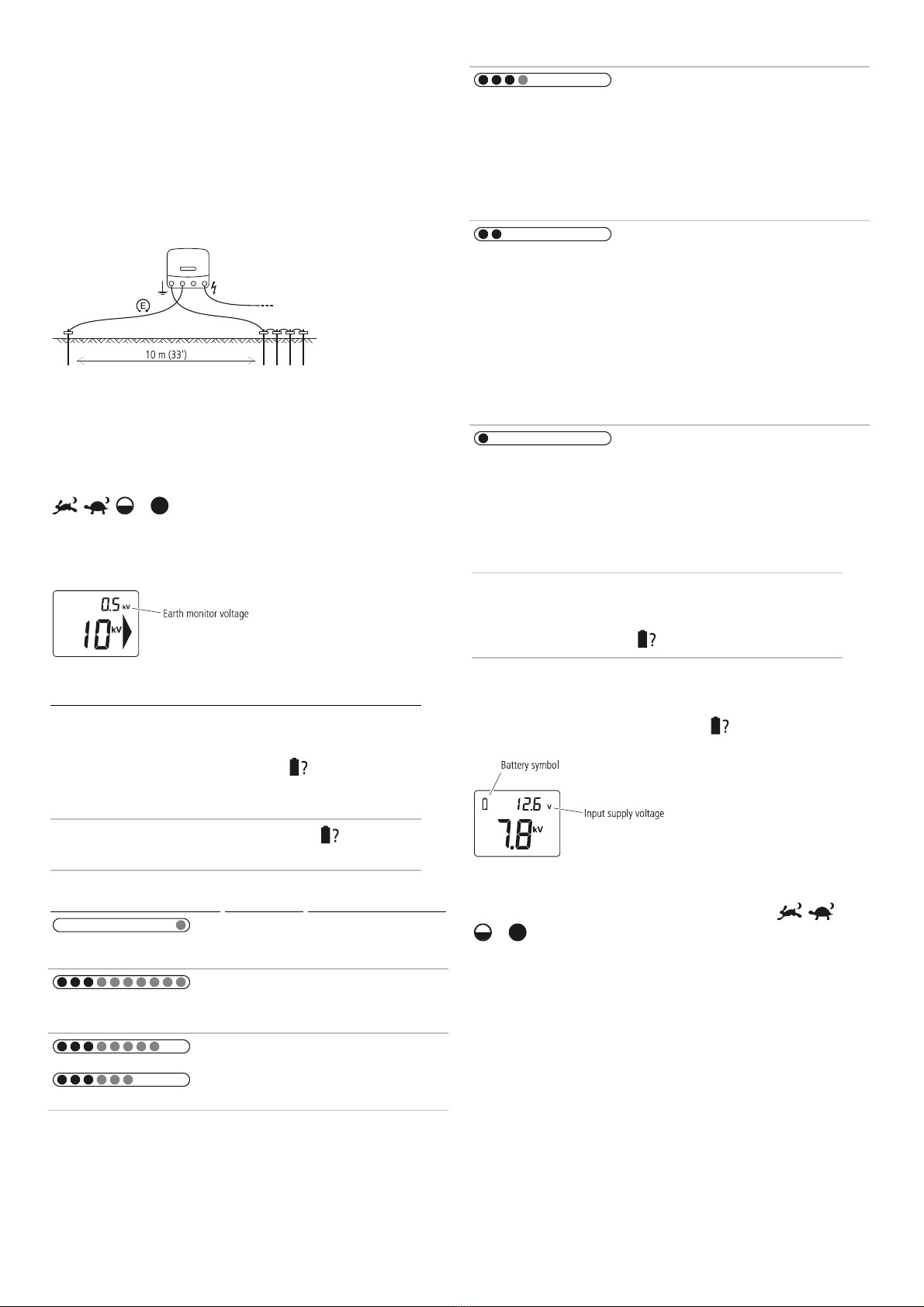
Earth monitoring (12000i, X12i, 412i, 6000i, 6000i-EU,
X6i, X6i-EU, 406i and 406i-EU energizers only)
The quality of the earth affects the fence voltage. The earth monitoring
feature allows you to keep an eye on the earth quality to make the
most of your electric fence. A low voltage on the earth monitor
indicates a good earth connection. A high voltage on the earth monitor
indicates a poor earth connection.
6
Setting up for earth monitoring
The earth monitoring feature works by comparing the voltage of the
energizer’s earth system with that of a separate earth rod. Ensure the
separate earth rod is at least 10 m (33’) away from any other earth
system including the energizer’s main earth system. Locate the earth
rod in the opposite direction to the lead out wire. Drive one 2 m (6’6”)
earth rod into the ground. Use high-voltage, insulated cable and an
earth clamp to connect the earth rod and the energizer’s Fence earth
monitor terminal. Make sure the insulation is stripped back to ensure
good contact between the wire and the earth rod.
Monitoring the earth
If the first Indicator light is illuminated permanently, this indicates that
the earth voltage is over 0.8 kV and that better earthing may be
beneficial. Either add more earth rods or find a better location for the
energizer earth system. The small digits on the LCD display show the
voltage going to the earth system when the selector switch is set to
, , or . The earth voltage should remain below 0.8 kV
at all times. If the earth monitor voltage numbers flash 3.0 kV, this
indicates the earth voltage is above 3.0 kV. See
Installing and testing
an earth system
on page 9 for information about installing an earth
system effectively.
Testing the battery voltage
The energizer’s Battery Test setting can be used to monitor the battery
voltage.
When the selector switch is set to Battery Test , the Indicator lights
show the input supply voltage. This can be useful in order to monitor
the battery charge level.
Note:
When the selector switch is set to Battery Test , the energizer
pulses at slow speed (2.5 seconds between pulses) and the fence is live.
Lights
Input supply
voltage
Battery-only installation
Above 17.0 V Abnormal conditions,
check battery and
connections.
12.6 V-17.0 V Full battery charge
voltage (80-100%):
•No action required.
or
12.3-12.6 V
12.0-12.3 V
Medium battery charge
voltage (50-80%):
•No action required.
11.7-12.0 V Low battery charge
voltage (20-50%):
•Monitor battery
voltage.
•Recharge the battery
to avoid long-term
damage to the
battery.
11.2-11.7 V Bad battery charge
voltage (10-20%):
•Recharge the battery
immediately.
•Energizer will
automatically revert
to Slow Speed and
Low Output Power in
order to preserve the
remaining power and
energy in the battery.
Below 11.2 V Very bad battery charge
voltage:
•Recharge the battery
immediately
•The energizer will not
function in order to
preserve the battery.
Notes:
-In extreme temperatures, these guidelines may not apply.
-The battery test results will display for 30 seconds after the selector
switch is set to Battery Test .
12000i, X12i, 412i, 6000i, 6000i-EU, X6i, X6i-EU, 406i and
406i-EU energizers only
When the selector switch is set to Battery Test , the LCD display also
displays the input supply voltage.
When the voltage is outside the normal range (below 11.8 V or above
17 V), the battery symbol flashes.
During normal operation, when the selector switch is set to , ,
or , if the battery voltage is bad, the battery symbol on the LCD
display flashes. Recharge the battery immediately.
Battery selection and management
This section refers exclusively to 12 V rechargeable batteries.
The batteries you select will depend on whether your installation is a
solar or a battery-only installation. For both types of installation, the
selector switch position you use most frequently will be a factor. Refer
to
Operation
on page 4 for an explanation of the function of the
selector switch.

7
Battery selection for a battery-only installation
As a guide, the amp hour (Ah) rating of the 12 V rechargeable batteries
required is shown below. This table is based on a 21 day operating
period between battery charging. Although operating time can exceed
21 days, this is likely to cause battery damage and will necessitate
frequent replacement of the battery. For best system reliability and long
term battery life, the preferred battery and charging regime is to use a
12 V rechargeable battery and to recharge it when it is half discharged.
For more information on checking the battery voltage, see
Testing the
battery voltage
on page 6.
Selector switch position
Recommended batteries
6 J models 12 J models
450 Ah 700 Ah
575 Ah 900 Ah
575 Ah 900 Ah
or
370 Ah 600 Ah
700 Ah 1100 Ah
Warning!
12 V rechargeable batteries must be used.
Battery selection for a solar installation
The battery and solar panels must be selected carefully to suit the
energizer’s electrical current consumption. As well as the position of the
selector switch position, the battery and solar panels you choose will
depend on the amount of sunshine at the location of the installation.
As a guide, the minimum amp hour (Ah) rating of the 12 V
rechargeable battery required is shown below. This table shows the
battery requirements for up to seven days of operation with little or no
sunlight. It takes into account the variety of solar panel and regulator
types that could be used in a solar installation. For more detailed
information, refer to www.tru-test.com.
Selector
switch
position
Current required (approximately) Minimum battery
capacity (80% discharge)
6 J models 12 J models 6 J models 12 J models
410 mA 700 mA 110 Ah 190 Ah
410 mA (day)
650 mA (night)
530 mA (24
hour average)
700 mA (day)
1100 mA (night)
900 mA (24 hour
average)
140 Ah 240 Ah
650 mA (day)
410 mA (night)
530 mA (24
hour average)
1100 mA (day)
700 mA (night)
900 mA (24 hour
average)
140 Ah 240 Ah
or
330 mA 580 mA 85 Ah 150 Ah
650 mA 1100 mA 170 Ah 290 Ah
Warning!
12 V rechargeable batteries must be used.
Battery management
Warning!
Batteries contain harmful chemicals and when used
incorrectly, may cause injury. Observe the guidelines for battery
care, maintenance and safety in this manual and in the
documentation supplied with your battery.
Battery charging
Warning!
-Do not attempt to recharge a non-rechargeable battery.
-When recharging a battery, ensure that there is adequate
ventilation to allow gases to disperse.
Regular recharging of the battery is essential. Use a suitable safety
approved battery charger and refer to the battery manufacturer’s
recommendations.
1Attach the positive (+) battery charger lead to the positive
terminal of the battery, and the negative (–) battery charger lead
to the negative terminal on the battery.
2Connect the battery charger’s input power plug to a mains or line
socket and turn on the power supply.
Caution!
Over-charging the battery will reduce its life. Do not
exceed the recommendations of the battery manufacturer on
recharging the battery from a mains-powered (line-powered) source.
Battery care and maintenance
•House the battery in a suitably designed battery box, if the battery
is likely to be exposed to the weather.
•When not in use, store the battery fully charged and recharge at
regular intervals (every 8 weeks).
•Recharge a discharged battery as soon as possible. Batteries
should not be left discharged.
•Inspect the battery regularly to ensure that the electrolyte level
does not fall below the surface of the battery plates.
•Top up the battery using distilled water. Do not overfill. Refer to
the battery manufacturer’s recommendations for more
information.
Battery safety
•Ensure that the battery is well ventilated when recharging.
•Avoid temperatures greater than 50 °C (120 °F).
•Ensure the battery is not exposed to naked flame or sparks.
Using a remote control handset
12000i, X12i, 412i, 6000i, 6000i-EU, X6i, X6i-EU, 406i, and 406i-EU
energizers will accept commands from a Tru-Test remote control
handset. No configuration is required. The energizer and remote control
are pre-programmed to communicate.
Note:
6000, 6000-EU, X6, X6-EU, 406 and 406-EU energizers cannot
be used with a remote control handset.

8
Activating the energizer for use with a remote control
handset
During the first 10 minutes of operation, the energizer’s remote control
feature can be activated. During this period, the large arrow on the LCD
display flashes to indicate this. The energizer will otherwise operate
normally.
To activate the remote control feature, turn off the energizer using a
remote control handset (see the remote control handset’s user manual
for details). The energizer will stop pulsing, and the last green light will
flash to indicate that the energizer is in standby mode. The large arrow
on the LCD remains on to indicate that activation has been successful.
Once the energizer’s remote control feature has been activated, you will
not need to perform the activation procedure again.
Note:
-If the energizer is not successfully activated within the first 10
minutes of operation, you will need to switch the energizer off and
on before you can try again.
-You can disable the remote control feature at any time. For
instructions, see the remote control handset’s user manual. If you
do not have a remote control handset, take the energizer to an
authorised service centre to have the feature disabled.
The remote control handset
The remote control handset is three tools in one. It acts as a:
•Remote control – Switching the energizer on or off from remote
locations on the electric fence system.
•Fault finder – Assisting in the location of faults anywhere on the
fence system.
•Voltmeter/Ammeter – Providing instant feedback on fence
performance (voltage and current)
For detailed instructions on using the remote control handset, refer to
the user manual supplied with the handset. Alternatively, the latest
copy of the user manual can be downloaded from www.trutest.com.
Warning!
The energizer will reactivate following a power failure,
even if it was switched off by a remote control handset before the
power failure. The fence should be regarded as live at all times,
regardless of the energizer switch position or the remote control
status. If you are working on a section of fence, isolate the section
with a cut-out switch, or disconnect the energizer from its power
source.
Building a permanent electric fence
Components of an electric fence
An electric fence system comprises the following elements:
•
An energizer.
•
An earth system.
This comprises a number of metal rods inserted
into the ground, which are connected to the Fence earth terminal
on the energizer.
•
Insulated underground cables.
Electric fence wire coated in
insulated plastic, suitable for use underground or going through
walls. Used to connect the energizer to the earth and fence.
•
An insulated fence.
Connected to the Fence output terminal of the
energizer. Fences can be made to a variety of designs (see below).
Other useful components that can be added:
Cut-out switches. Installed at regular intervals, these allow
you to isolate sections of the fence for repair.
Lightning diverter kit. Used to minimise the damage to your
energizer from lightning conducted down the fence line.
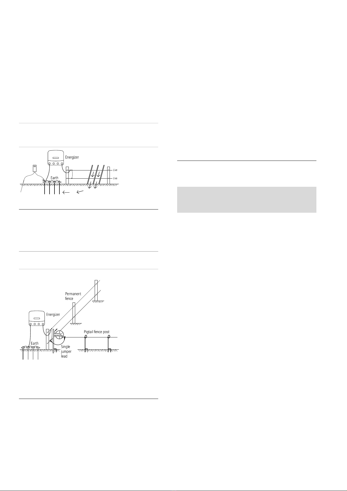
Typical installation
The animal receives a shock when it completes a circuit between the
fence and the earth system. The fence below has all live wires and
requires conductive soils. This type of fence is often referred to as an
‘all-live’ or ‘earth-return’ fence.
Alternative installation
For poor conductivity soils (dry or sandy), a ‘fence-return’ or ‘earth-wire-
return’ system is recommended. With this type of fence, the Fence earth
terminal is connected directly to at least one non-electrified fence wire
(earth wire). The animal gets maximum shock from touching a live wire
and an earth wire at the same time.
Bi-polar installation
In areas with poor earthing conditions, a ‘bi-polar’ installation may be
used to enhance the performance of the fence. With a bi-polar
installation, all fence wires are insulated. Alternate fence wires are
interconnected to form one negatively charged circuit and one positively
charged circuit. The energizer passes half the output voltage to the
negatively charged wires and half the output voltage to the positively
charged wires. The animal gets a shock from touching a positive wire or
a negative wire OR, if touching both a positive and negative wire
simultaneously it gets a stronger shock.
To construct a bi-polar fence:
1Interconnect fence wires so that there are two different circuits, as
shown in the diagram.
2Connect the Fence half voltage terminal (yellow) to the earth
system using insulated cable.
3Connect the Fence earth terminal (green) to the negative wires.
4Connect the Fence full voltage terminal (red) to the positive wires.
Note:
The earth monitoring feature cannot be used with a bi-polar
installation.
9
Reducing the fence voltage output
In some areas, it may desirable to have a reduced fence voltage output,
for example where there is a risk of fire or where there is a chance that
people might come into contact with the electric fence (e.g. around a
house or next to a public roadway).
To reduce the fence voltage, use the Fence half voltage terminal
(yellow) instead of the Fence full voltage terminal to connect the
energizer to the fence. See the
Installation section
on page 3.
When the Fence half voltage terminal (yellow) is used, the fence voltage
will not exceed 5 kV, however the output power remains the same.
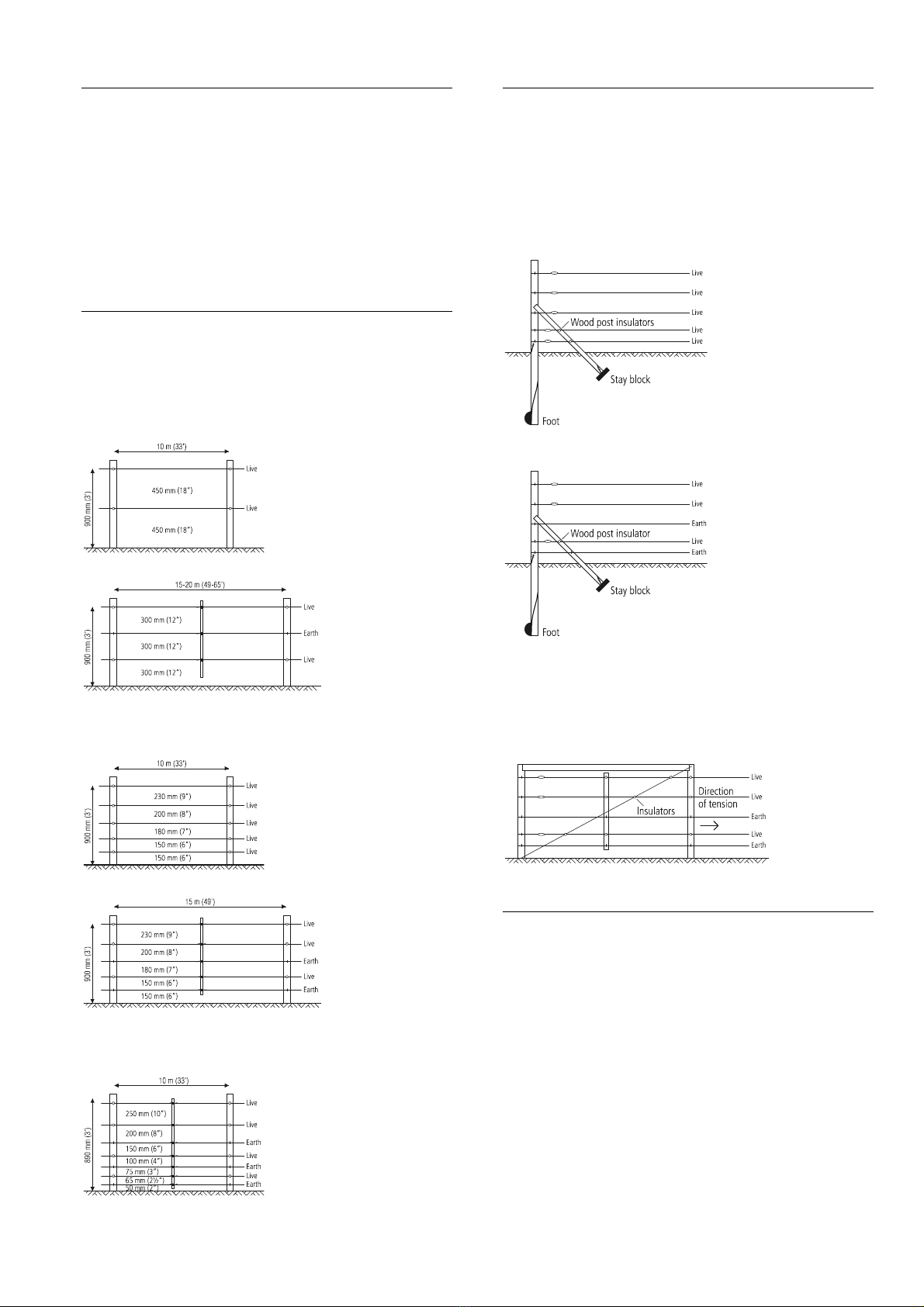
Fence designs
Fences can be constructed to suit the type of livestock and materials
available. Discuss with your reseller which design best suits your needs.
Some suggested fence configurations are below.
Cattle and horses
10-15 m (33-49’) spacing, posts only
15-20 m (49-65’) spacing with droppers
Sheep, goats, cattle and horses
10 m (33’) spacing, posts only
15 m (49’) spacing with droppers
Wild animals
7 wire, 10 m (33’) spacing with droppers
End assemblies
Angle stay
Suitable for field gate, high-tension strainer.
After firmly setting the footed strainer in the ground, dig in the stay
block just below ground level, at a distance to ensure the angle stay will
be held snugly in position. The stay can be levered into position with a
spade.
All-live system
Fence-return system
Horizontal stay
Suitable for field gate, high-tension strainer.
Very simple to erect and most suitable as a high tension strainer,
excellent in areas where the soil gets very wet or where heavy frost
occurs.
Installing and testing an earth system
Select a suitable site for the earth system. Sites need to be:
•At least 10 m (33’) from other earth systems (e.g. telephone,
mains power or the earth system of another energizer).
•Away from stock or other traffic that could interfere with the
installation.
•At a site that can be easily observed for maintenance.
•Ideally at a site that has damp soil (e.g. a shaded or swampy
location). Note that the earth does not need to be directly
adjacent to the energizer installation.
Drive four 2 m (6’6”) earth rods into the ground. Use high-voltage,
insulated cable and earth clamps to continuously connect the earth rods
and the energizer’s Fence earth terminal. Make sure the insulation is
stripped back to ensure good contact between the wire and the earth
rod.
Test the earth system, using the following procedure:
1Turn off the energizer.
10
2At least 100 m (330’) away from the energizer, short circuit the
fence by laying several steel rods or lengths of pipe against the
fence. In dry or sandy conditions, it may be necessary to drive the
rods up to 300 mm (12”) into the earth.
Note:
It is not acceptable to short-circuit a fence return system to
the earth wire of the fence.
3Turn the energizer back on.
4Using an electric fence voltmeter, ensure that the fence voltage is
below 2 kV.
5
Check your earth system.
Insert the voltmeter’s earth probe into
the ground at the full extent of the lead, and clip the other lead to
the last earth rod. The voltmeter should not read more than
0.8 kV. Anything higher than this indicates that better earthing is
required. Either add more earth rods or find a better ground area
to drive in the earth rods.
Note:
When earthing energizers located in dairies, earth at least 20 m
(65’) away from the dairy using double-insulated lead-out wire to avoid
touching the dairy building or equipment.
Temporary electric fencing
A temporary fence can be quickly erected and easily moved allowing the
farmer to:
•Make smaller paddocks (fields)
•Keep herds of animals separated
•Ration feed
Note:
Use more wires for smaller animals and wild animals. Politape
should be used when greater visibility is required (e.g. horses).
An example of a temporary fence is shown below.
Safety considerations
Definition of special terms
Energizer
– An appliance that is intended to periodically deliver voltage
impulses to a fence connected to it.
Fence
– A barrier for animals or for the purpose of security, comprising
one or more conductors such as metal wires, rods or rails.
Electric fence
– A barrier which includes one or more electric
conductors, insulated from earth, to which electric pulses are applied by
an energizer.
Fence circuit
– All conductive parts or components within an energizer
that are connected or are intended to be connected, galvanically, to the
output terminals.
Earth electrode
– Metal structure that is driven into the ground near an
energizer and connected electrically to the Fence earth terminal of the
energizer, and that is independent of other earthing arrangements.
Connecting lead
– An electric conductor, used to connect the energizer
to the electric fence or the earth electrode.
Electric animal fence
– An electric fence used to contain animals within
or exclude animals from a particular area.
Electric security fence
– A fence used for security purposes which
comprises an electric fence and a physical barrier electrically isolated
from the electric fence.
Physical barrier
– A barrier not less than 1.5 m (5’) high intended to
prevent inadvertent contact with the pulsed conductors of the electric
fence. Physical barriers are typically constructed from vertical sheeting,
rigid vertical bars, rigid mesh, rods or chainwire mesh.
Requirements for electric animal fences
Electric animal fences and their ancillary equipment shall be installed,
operated and maintained in a manner that minimises danger to
persons, animals or their surroundings.
Warning!
Avoid contacting electric fence wires especially with the
head, neck or torso. Do not climb over, through or under a multi-
wire electric fence. Use a gate or a specially designed crossing point.
This energizer is not intended for use by persons (including children)
with reduced physical, sensory or mental capabilities, or lack of
experience and knowledge, unless they have been given supervision or
instruction concerning use of the energizer by a person responsible for
their safety.
Children should be supervised to ensure that they do not play with the
energizer.
Electric animal fence constructions that are likely to lead to the
entanglement of animals or persons shall be avoided.
An electric animal fence shall not be supplied from two separate
energizers or from independent fence circuits of the same energizer.
For any two separate electric animal fences, each supplied from a
separate energizer independently timed, the distance between the wires
of the two electric animal fences shall be at least 2.5 m (8’). If this gap
is to be closed, this shall be effected by means of electrically non-
conductive material or an isolated metal barrier.
Barbed wire or razor wire shall not be electrified by an energizer.
A non-electrified fence incorporating barbed wire or razor wire may be
used to support one or more off-set electrified wires of an electric
animal fence. The supporting devices for the electrified wires shall be
constructed so as to ensure that these wires are positioned at a
minimum distance of 150 mm (6”) from the vertical plane of the non-
electrified wires. The barbed wire and razor wire shall be earthed at
regular intervals.
Follow our recommendations regarding earthing. See
Installing and
testing an earth system
on page 9.
A distance of at least 10 m (33’) shall be maintained between the
energizer earth electrode and any other earthing system connected
parts such as the power supply system protective earth or the
telecommunication system earth.
Connecting leads that are run inside buildings shall be effectively
insulated from the earthed structural parts of the building. This may be
achieved by using insulated high voltage cable.
Connecting leads that are run underground shall be run in conduit of
insulating material or else insulated high voltage cable shall be used.

11
Care must be taken to avoid damage to the connecting leads due to the
effects of animal hooves or vehicle wheels sinking into the ground.
Connecting leads shall not be installed in the same conduit as the
mains supply wiring, communication cables or data cables.
Connecting leads and electric animal fence wires shall not cross above
overhead power or communication lines.
Crossings with overhead power lines shall be avoided wherever
possible. If such a crossing cannot be avoided it shall be made
underneath the power line and as nearly as possible at right angles to
it.
If connecting leads and electric animal fence wires are installed near an
overhead power line, the clearances shall not be less than those shown
in the table below.
Minimum clearances from power lines for electric animal fences
Power line voltage Clearance
≤1000 V 3 m (10’)
>1000 V to ≤33,000 V 4 m (13’)
>33,000 V 8 m (27’)
If connecting leads and electric animal fence wires are installed near an
overhead power line, their height above the ground shall not exceed 3
m (10’). This height applies to either side of the orthogonal projection
of the outermost conductors of the power line on the ground surface,
for a distance of:
•2 m (6’6”) for power lines operating at a nominal voltage not
exceeding 1000 V.
•15 m (50’) for power lines operating at a nominal voltage
exceeding 1000 V.
Electric animal fences intended for deterring birds, household pet
containment or training animals such as cows need only be supplied
from low output energizers to obtain satisfactory and safe performance.
In electric animal fences intended for deterring birds from roosting on
buildings, no electric fence wire shall be connected to the energizer
earth electrode. A warning sign shall be fitted to every point where
persons may gain ready access to the conductors.
Where an electric animal fence crosses a public pathway, a non-
electrified gate shall be incorporated in the electric animal fence at that
point or a crossing by means of stiles shall be provided. At any such
crossing, the adjacent electrified wires shall carry warning signs.
Any part of an electric animal fence that is installed along a public road
or pathway shall be identified at frequent intervals by warning signs
securely fastened to the fence posts or firmly clamped to the fence
wires.
•The size of the warning sign shall be at least 100x200 mm (4x8”).
•The background colour of both sides of the warning sign shall be
yellow. The inscription on the sign shall be black and shall be
either:
or the substance of “CAUTION: Electric fence”.
•The inscription shall be indelible, inscribed on both sides of the
warning sign and have a height of at least 25 mm (1”).
Ensure that all mains-operated, ancillary equipment connected to the
electric animal fence circuit provides a degree of isolation between the
fence circuit and the supply mains equivalent to that provided by the
energizer.
Protection from the weather shall be provided for the ancillary
equipment unless this equipment is certified by the manufacturer as
being suitable for use outdoors, and is of a type with a minimum degree
of protection IPX4.
Important safety instructions for Class 2 power units
(USA/Canada only)
When using electrical products, basic precautions should always be
practiced including the following:
1READ AND FOLLOW ALL SAFETY INSTRUCTIONS
2Read and follow all instructions that are on the product or
provided with the product.
3Do not use an extension cord.
4Reference the National Electrical Code, ANSI/NFPA 70, specifically
for the installation of wiring and clearances from power and
lighting conductors.
5Installation work and electrical wiring must be done by qualified
person(s) in accordance with all applicable codes and standards,
including fire-rated construction.
6Do not install or use within 3 m (10’) of a pool.
7Do not use in a bathroom.
8WARNING: Risk of Electric Shock. When used outdoors, install
only to a covered Class A GFCI protected receptacle that is
weatherproof with the power adaptor connected to the receptacle.
If one is not provided, contact a qualified electrician for proper
installation. Ensure that the power adaptor and cord do not
interfere with completely closing the receptacle cover.
9WARNING: Risk of Fire. Installation involves special wiring
methods to run wiring through a building structure. Consult a
qualified electrician.
10 WARNING: Risk of Electric Shock. Mount the unit at a height
greater than 30 cm (1’) from the ground surface.
11 SAVE THESE INSTRUCTIONS – This manual contains important
safety and operating instructions for power adaptors.
Important safety instructions for power adaptors (all
other countries)
DANGER! RISK OF ELECTRIC SHOCK. INDOOR DRY
LOCATIONS ONLY.
Frequently asked
questions/Troubleshooting
What voltage is required to control animals?
4 kV is widely accepted as an adequate voltage to control animals.
However, you also require a well constructed fence system to ensure
that animals cannot push through electrified wires.
The fence voltage is below 4 kV. How do I increase the voltage?
Check the energizer.
Ensure that the energizer is on and set to operate
at full power. Disconnect the fence wire from the energizer’s fence
output terminal. Measure the voltage across the energizer terminals
using a Fault Finder, Digital Voltmeter or a remote control handset. If
the voltage is less than 6 kV, the energizer may require servicing.
Check the energizer earthing.
For 12000i, X12i, 412i, 6000i, 6000i-EU,
X6i, X6i-EU, 406i and 406i-EU energizers, check that the earth monitor
voltage on the LCD display is below 0.8 kV, see
Earth monitoring
on
page 5. For 6000, 6000-EU, X6, X6-EU, 406 and 406-EU energizers,

12
use the procedure described in
Installing and testing an earth system
on
page 9.
Check the fence system for faults.
The most common source of low
voltage is faults on the fence line.
If the fence, earth and energizer are in good condition and the voltage
is still below 4 kV, talk to your nearest reseller. Recent extensions to
your fence, a poor fence layout, or soil conditions may be causing
inadequate voltage.
How do I locate faults?
The recommended tool for locating faults is a Fault Finder or remote
control handset. These have a combined voltage and current meter
which allows you to rapidly locate sources of current leakage.
Alternatively, use a Digital Voltmeter. Use cut-out switches to turn off
the power to different sections of the farm. If the voltage on the fence
increases when a section of the farm is turned off, then investigate that
section for possible faults.
There are no lights flashing on the energizer
Ensure the power supply is on. Check the fence system for faults (see
above). Check the energizer (see above). If the energizer still does not
operate, it may require servicing.
The energizer does not respond to commands from the remote
control handset
See the Frequently Asked Questions/Troubleshooting section in the
remote control handset’s user manual.
I want to disable the energizer’s remote control feature
If you have a remote control handset, see the remote control handset’s
user manual for instructions. If not, take the energizer to an authorised
service centre to have the feature disabled.
Identifying faults using the LCD display
and the indicator lights
If... This means that...
The energizer is not pulsing
and the first red Indicator light
is flashing...
The battery connections may be faulty.
Check all battery connections. Check the
battery voltage immediately using the
battery test setting. See
Testing the
battery voltage
on page 6.
The first red Indicator light is
flashing and other indicator
lights are on...
The energizer has a fault. If the display
persists and does not return to normal,
contact your service agent for advice.
The energizer is pulsing slowly
and has a reduced output
voltage...
The battery voltage may be low and the
energizer has reverted to Slow Speed and
Low Output Power in order to preserve
the remaining power and energy in the
battery.
If... This means that...
(6000i-EU, X6i-EU, 406i-EU,
6000-EU, X6-EU and 406-EU
energizers only)
The warning light is flashing
and a warning buzzer is
sounding…
The energizer has detected a sudden
increase in the load on the fence.
Switch the energizer off, locate and
remedy fault then turn the energizer on
again.
For example, this may occur:
•if a cutout switch is closed,
connecting a heavily loaded section
of the fence to the energizer
•if a branch falls on the fence
•if the fence or cable connecting
energizer to it experiences a sudden
short to ground
•if something becomes entangled in
the fence.
(12000i, X12i, 412i, 6000i,
6000i-EU, X6i, X6i-EU, 406i
and 406i-EU energizers only)
The output voltage digits (large
digits on the LCD display) flash
1.0 kV...
The fence voltage is below 1000 V. There
is a serious fault on the fence line. See
“How do I locate faults?” in
Frequently
asked questions/Troubleshooting
on
page 11.
(12000i, X12i, 412i, 6000i,
6000i-EU, X6i, X6i-EU, 406i
and 406i-EU energizers only)
The first red Indicator light is
illuminated permanently...
The earth monitor voltage is too high.
Use the earth monitoring feature to
monitor the earth. See
Earth monitoring
on page 5.
(12000i, X12i, 412i, 6000i,
6000i-EU, X6i, X6i-EU, 406i
and 406i-EU energizers only)
The battery symbol on the LCD
is flashing...
The battery voltage is bad. Check the
battery voltage immediately, using the
battery test setting. See
Testing the
battery voltage
on page 6.
(12000i, X12i, 412i, 6000i,
6000i-EU, X6i, X6i-EU, 406i
and 406i-EU energizers only)
The right arrow on the LCD is
flashing...
During the first 10 minutes of operation,
the energizer’s remote control feature
can be activated. During this period, the
large arrow on the LCD display flashes to
indicate this. This occurs each time the
energizer is switched on when the
energizer’s remote control feature has
not been activated This is part of normal
operation.
(12000i, X12i, 412i, 6000i,
6000i-EU, X6i, X6i-EU, 406i
and 406i-EU energizers only)
The energizer is not pulsing
and the last green Indicator
light is flashing...
The energizer has been switched off by a
remote control handset. If you think your
energizer might be being controlled by a
neighbour’s remote control handset and
you own a remote control handset
yourself, change your energizer’s address
setting (see the remote control handset’s
user manual). If you do not have a
remote control handset, take the
energizer to an authorised service centre
to have the remote control feature
disabled.

13
Servicing
This energizer uses Double Insulation, where two systems of insulation
are provided instead of grounding. No equipment grounding means is
provided in the supply cord of a double-insulated energizer, nor should
a means for equipment grounding be added to the energizer. Servicing
a double-insulated energizer requires extreme care and knowledge of
the system and should only be done by qualified service personnel.
Replacement parts for a double-insulated energizer must be identical to
the parts they replace. A double-insulated energizer is marked with the
words DOUBLE INSULATION or DOUBLE INSULATED and/or the symbol
below.
Product specifications
6 J models 12 J models
Power supply 12 V battery,
or approved power adaptor 100-120 V or
100-240 V
Power consumption using
a power adaptor
10 W 15 W
Current consumption using a 12 V rechargeable battery
Battery Test 410 mA 700 mA
Slow Speed-Day/
Fast Speed-Night
410 mA (day)
650 mA (night) or
530 mA (24 hour
average)
700 mA (day)
1100 mA (night) or
900 mA (24 hour
average)
Fast Speed-Day/
Slow Speed-Night
650 mA (day)
410 mA (night) or
530 mA (24 hour
average)
1100 mA (day)
700 mA (night) or
900 mA (24 hour
average)
Half Output Power 330 mA 580 mA
Full Output Power 650 mA 1100 mA
Maximum output voltage 9.5 kV 9.2 kV
Maximum output energy 6.2 J at 100 Ω12.4 J at 75 Ω
Maximum stored energy 9 J 16 J
Values are typical and normal production tolerances of ±10% should be allowed for.

14
SVENSKA
Elstängsel och ditt aggregat
Gratulerar till ditt köp av aggregatet. Produkten har konstruerats enligt
den senaste teknologin och konstruktionstekniken. Den har utformats
för att ge en överlägsen prestation och för många års användning.
Det är viktigt att du läser instruktionerna noggrant. De innehåller viktig
säkerhetsinformation och hjälper dig se till att elstängselsystemet ger
maximal prestanda och pålitlighet.
Hur fungerar ett elstängsel?
Ett elstängselsystem omfattar ett aggregat och ett isolerat stängsel.
Aggregatet lägger mycket korta elektriska pulser på stängselledningen.
Dessa pulser har hög spänning men mycket kort varaktighet (mindre än
3/10 000-dels sekund). En stöt från en elektrisk stängselpuls är dock
mycket obehaglig, och djuren lär sig snabbt att respektera elstängsel.
Ett elstängsel är inte bara en fysisk barriär utan också en stark
psykologisk barriär.
Vilka är fördelarna med ett elstängsel?
Det finns många fördelar med ett elstängsel jämfört med konventionella
stängsel.
•Kräver mindre arbete och material för att konstruera.
•Flexibelt att lägga till fler beteshagar när de behövs. Avbetning i
smala strängar kan tillåta att temporära stängsel sätts upp snabbt
och lätt.
•Kontrollerar flera olika slags djur.
•Minimerar skada på dyrbar boskap jämfört med andra
stängselmekanismer, till exempel taggtråd.
Modeller som täcks av denna bruksanvisning
Denna bruksanvisning täcker olika aggregatmodeller:
12000i,
X12i, 412i
12 J-modeller. Dessa aggregat har en LCD-display, en
jordningsövervakningsfunktion och kan användas med
fjärrkontroll.
6000i, X6i,
406i
6 J-modeller. Dessa aggregat har en LCD-display, en
jordningsövervakningsfunktion och kan användas med
fjärrkontroll.
6000i-EU,
X6i-EU,
406i-EU
6 J-modeller sålda i Europa. Dessa aggregat har en LCD-
display, en jordningsövervakningsfunktion och kan användas
med fjärrkontroll. Om aggregatet detekterar att stängslets
belastning plötsligt stiger avges en varning. Aggregatet kan
öka utgångseffekten för att på ett effektivare sätt förse
stängslet med ström.
6000, X6,
406
6 J-modeller.
6000-EU,
X6-EU,
406-EU
6 J-modeller sålda i Europa. Om aggregatet detekterar att
stängslets belastning plötsligt stiger avges en varning.
Aggregatet kan öka utgångseffekten för att på ett
effektivare sätt förse stängslet med ström.
OBS:
De aggregat som räknas upp här finns inte tillgängliga på alla
marknader.
Förklaring av symboler på aggregatet
Stängslets jordningsuttag. Anslut stängslets jordningsuttag till
aggregatets jordningssystem.
Stängslets jordningsövervakningsuttag
(endast aggregat 12000i,
X12i, 412i, 6000i, 6000i-EU, X6i, X6i-EU, 406i och 406i-EU).
Anslut stängslets jordningsövervakningsuttag till en separat
jordningsstake. Se
Jordningsövervakning
på sidan 18.
Stängslets halvspänningsuttag. För användning i områden med
dålig jordning, se
Bipolär installation
på sidan 20 eller i områden
där en gräns på 5 kV stängselspänning önskas (t.ex. där det
finns risk för brand eller att någon kan ta på stängslet), se
Minskning av stängslets spänningsutgång
på sidan 21. Anslut
stängslets halvspänningsuttag till stängslet.
Stängslets helspänningsuttag. Anslut stängslets
helspänningsuttag till stängslet.
Risk för elchock! Detta aggregat får endast öppnas eller
repareras av behörig personal.
Läs alla instruktionerna innan användning.
Denna symbol på produkten eller dess förpackning indikerar att
denna produktion inte får kasseras med vanliga sopor. Det är i
stället din skyldighet att kassera utrustningen genom att lämna
in den på en särskild återvinningscentral för elektrisk och
elektronisk utrustning. Den separata insamlingen och
återvinningen av utrustningen hjälper till att bevara naturliga
resurser och se till att den återvinns på ett sätt som skyddar
människa och miljö. För mer information om var du kan lämna in
utrustningen för återvinning, kontakta din lokala
återvinningsstation eller handlaren där du köpte produkten.
Aggregatet har en dubbelisolerad konstruktion.
Endast aggregat 6000i
-
EU, X6i
-
EU, 406i
-
EU, 6000
-
EU, X6
-
EU
och 406
-
EU
Aggregat markerade med denna symbol är aggregat med
tidsfördröjning avsedda för elektriska stängsel med en
fördröjning på 50 sekunder. Se
Stängselspänning
på sidan 17.
Varning!
-Stäng av aggregatet innan installation eller utförande av arbeten
på stängslet.
-Läs alla säkerhetsbeaktanden noga. Se
Säkerhetsåtgärder
på
sidan 22.
-Kontrollera din installation för att försäkra dig om att den
överensstämmer med lokala säkerhetsbestämmelser.
-Europa - Om temperaturen ligger under 5 °C måste aggregatet
placeras under ett skydd och alla eventuella kablar som är
anslutna får inte hanteras.
-Anslut inte samtidigt till ett stängsel och till en annan installation
såsom en boskaps- eller fågelinhägnad. I annat fall kan
blixtnedslag i ditt stängsel spridas till alla andra enheter.
-Använd endast den eluttagsadapter eller de batteritrådar som
medföljer aggregatet eller en originalreservdel.
Anmärkningar:
-Denna produkt har konstruerats för användning med eldjurstängsel.
-Ha alltid denna bruksanvisning nära till hands.

15
Aggregatets delar
Installation
Läs igenom alla säkerhetsinstruktioner i bruksanvisningen och alla
relevanta gällande nationella, regionala och lokala säkerhetsstandarder
innan aggregatet installeras.
Välja en plats för installationen
Följ dessa riktlinjer när du väljer plats för installationen.
Välj en plats där:
•en god jordning kan erhållas
•aggregatets jordledningssystem finns minst 10 m från andra
jordledningssystem (t.ex. telefon, kraftnät eller jordledningssystem
från ett annat aggregat).
•barn och djur får inte kan komma i kontakt med installationen
Försäkra dig om att aggregatet installeras:
•intill det elektriska stängslet
•företrädesvis i mitten på det elektriska stängselsystemet
•i närheten av ett nät-/ledningseluttag (om en nät-
/ledningsförsörjning för att ge ström till aggregatet används)
•minst 1 m från och inte direkt ovanför batteriet (om ett batteri
används för att försörja aggregatet med ström)
Om din installation finns utomhus måste du även se till att:
•den finns på en jämn yta på avstånd från vattendrag
•inuti en skyddsstängsel, om nödvändigt.
Använda strömadaptern och batteristift
Aggregatet försörjs med en strömadapter (för anslutning till nät-
/ledningsström) och en uppsättning batteristift (för anslutning till ett
batteri). Innan en strömadapter eller batteristift ansluts, säkerställ att
aggregatets väljarbrytare är inställd på Av .
För att använda strömadaptern:
1Anslut strömadaptern till strömingångsuttaget på baksidan av
aggregatet.
2Anslut strömadaptern till ett lämpligt nät-/ledningsuttag och
försäkra dig om att det finns 25 mm utrymme runt
strömadaptern.
För att avlägsna strömadaptern:
1Koppla från strömadaptern från nät-/ledningsströmmen.
2Dra i den vita kopplingen för att avlägsna strömadapterkontakten
från strömingångsuttaget på baksidan av aggregatet.
Använda batteristiften:
1Sätt i batteristiftet i strömingångsuttaget på baksidan av
aggregatet.
2Anslut aggregatet till batteriet med hjälp av batteristiften som
fanns med i leveransen. Fäst fast den röda klämman på den
positiva (+) sidan på batteriet och den svarta klämman på dess
negativa (-) sidan.
Observera:
Om aggregatet ska användas som en del av en permanent
installation utomhus, som t.ex. för en solinstallation, måste
batteristiftsklämmorna bytas ut mot permanenta batterianslutningar.
Avlägsna batteristiften:
1Avlägsna klämmorna från batteripolerna.
2Håll fast batteristiftet med gummihylsan vid slutet av ledningen.
Dra ordentligt för att få ut anslutningen från strömingångsuttaget
på baksidan av aggregatet.

16
Installera aggregatet inomhus
Aggregatet måste installeras inomhus, (under ett skydd) om den försörjs
av ett eluttag.
Varning!
-Använd inte förlängningssladd.
-Ha 25 mm utrymme runt eladaptern.
Installera aggregatet inomhus:
1Välj en lämplig monteringsplats. Se
Välja en plats för
installationen
på sidan 15.
2Montera aggregatet på en vägg 1,7 m över marken. Använd
mallen som finns tryckt på baksidan av denna bruksanvisning, om
nödvändigt.
3Anslut stängslets jordningsuttag (grönt) till aggregatets
jordningssystem.
4
Endast aggregat 12000i, X12i, 412i, 6000i, 6000i
-
EU, X6i,
X6i
-
EU, 406i och 406i
-
EU:
Om jordningsövervakning önskas,
anslut stängslets jordningsövervakningsuttag (svart) till en separat
jordningsstake. För mer information, se
Jordningsövervakning
på
sidan 18.
5Anslut stängslets helspänningsuttag (rött) eller stängslets
halvspänningsuttag (gult) till stängslet.
6Anslut aggregatet till eluttaget med hjälp av den medlevererade
eluttagsadaptern. Se
Använda strömadaptern och batteristift
på
sidan 15.
OBS!
För information om hur stängslets halvspänningsuttag används
för en tvåpolig stängselmontering, se
Bipolär installation
på sidan 20.
För information om hur stängslets halvspänningsuttag används för att
reducera stängslets spänningsutgång, se
Reducera stängslets
utgångsspänning
på sidan 21.
OBS!
Om aggregatet installeras inomhus kan det försörjas med ett
batteri istället för el från eluttaget, om nödvändigt.
Varning!
Om ett batteri används för att försörja ett aggregat som är
installerat inomhus, se till att det finns tillräcklig ventilation för att
tillåta gaser att upplösas.
Installera aggregatet utomhus
Aggregatet kan installeras utomhus och försörjas av ett batteri.
Varning!
Försörj inte aggregatet med el från eluttaget om det
installeras utomhus.
Installera aggregatet utomhus:
1Välj en lämplig monteringsplats. Se
Välja en plats för
installationen
på sidan 15.
2Montera aggregatet på en stolpe. Använd mallen som finns tryckt
på baksidan av denna bruksanvisning, om nödvändigt.
3Anslut stängslet till jordningsuttaget (grönt) på aggregatets
jordningssystem.
4
Endast aggregat 12000i, X12i, 412i, 6000i, 6000i
-
EU, X6i,
X6i
-
EU, 406i och 406i
-
EU:
Om jordningsövervakning önskas,
anslut stängslets jordningsövervakningsuttag (svart) till en separat
jordningsstake. För mer information, se
Jordningsövervakning
på
sidan 18.
5Anslut stängslets helspänningsuttag (rött) eller stängslets
halvspänningsuttag (gult) till stängslet.
6Anslut aggregatet till batteriet med de medlevererade
batteritrådarna. Se
Använda strömadaptern och batteristift
på
sidan 15.
OBS:
För information om hur stängslets halvspänningsuttag används för
en tvåpolig stängselmontering, se
Bipolär installation
på sidan 20. För
information om hur stängslets halvspänningsuttag används för att
reducera stängslets spänningsutgång, se
Reducera stängslets
utgångsspänning
på sidan 21.
Montera aggregatet som en del av en
solpanelsinstallation
Aggregatet kan installeras med solpaneler som en del av en
solpanelsinstallation.
En solpanelsinstallation består av följande delar:
•Aggregatet
•Ett batteri (eller batteribank)
•En eller flera solpaneler
•Ett jordningssystem för aggregatet.
För information om vilken typ av batterier som ska användas för en
solpanelsinstallation, se
Välja batteri för en solpanelsinstallation
på
sidan 19.
Den strömkapacitet som krävs för solpaneler beror på de lokala
villkoren. För att få hjälp med att placera solpanelen rätt, se
leverantören av din solpanel och hänvisa till din lokala väderlekstjänst.
För mer information om solpanelsinstallationer, se www.tru-test.com.
Varning!
Försörj inte aggregatet med el från eluttaget om det
installeras utomhus.
Montera aggregatet som en del av en solpanelsinstallation:
1Välj en lämplig monteringsplats. Se
Välja en plats för
installationen
på sidan 15. För solpanelsinstallationer är det viktigt
att välja en plats där solpaneler inte utsätts för skugga.
2Vänd solpanelen norrut i den södra hemisfären och söderut i den
norra hemisfären.
3Luta panelen så att den är vänd direkt mot midvinter
middagssolen. Om nödvändigt för att öka effektiviteten, justera
lutningsvinkeln vid olika tider på året.
4När solpanelen är rätt placerad, fäst aggregatet på baksidan av
panelen. Eller montera aggregatet på en stolpe. Använd mallen
som finns tryckt på baksidan av denna bruksanvisning, om
nödvändigt.

17
5Anslut stängslet till jordningsuttaget (grönt) på aggregatets
jordningssystem.
6
Endast aggregat 12000i, X12i, 412i, 6000i, 6000i
-
EU, X6i,
X6i
-
EU, 406i och 406i
-
EU:
Om jordningsövervakning önskas,
anslut stängslets jordningsövervakningsuttag (svart) till en separat
jordningsstake. För mer information, se
Jordningsövervakning
på
sidan 18.
7Anslut stängslets helspänningsuttag (rött) eller stängslets
halvspänningsuttag (gult) till stängslet.
8Anslut batteriet till solpanelen.
9Anslut aggregatet till batteriet med de batteritrådar som medföljer
men byt ut batteritrådsklämmorna mot permanenta
batterianslutningar. Se
Använda strömadaptern och batteristift
på
sidan 15.
Användning
Välj lämplig pulshastighet och nivå på utgångseffekten med
väljaromkopplaren.
Endast aggregat 12000i, X12i, 412i, 6000i, 6000i
-
EU, X6i, X6i-EU,
406i och 406i
-
EU:
När aggregatet sätts på visar LCD-displayen och indikatorlamporna
firmwareversion och fjärrkontrolladressinställningar (krävs endast för
avancerad felsökning och underhåll) i några sekunder. Efter detta
återgår aggregatet till normal drift. I dåliga ljusförhållanden när
väljaromkopplarens position ändras tänds LCD-displayen i 20 sekunder.
Endast aggregat 6000, 6000-EU, X6, X6-EU, 406 och 406-EU:
Aggregatet påbörjar normal drift inom 6 sekunder efter påsättning.
Använda väljaromkopplaren
Inställning Beskrivning
Av Aggregatet är avstängt och inte i drift.
När väljaromkopplaren är i positionen
Av reagerar aggregatet inte på
kommandon från en fjärrkontroll.
Batteritest Batteriets spänning visas av
indikatorlamporna (alla modeller) och
på LCD:n (endast aggregat 12000i,
X12i, 412i, 6000i, 6000i-EU, X6i,
X6i-EU, 406i, 406i-EU). Se
Test av
batteriets spänning
på sidan 18. När
denna inställning används drivs
aggregatet med långsam hastighet
(2,5 sekunder mellan pulserna).
Långsam hastighet - dag
Snabb hastighet - natt
Aggregatet drivs med långsam
hastighet (2,5 sekunder mellan pulser)
på dagen och snabb hastighet (1,5
sekunder mellan pulser) på natten. När
denna inställning används drivs
aggregatet med full energi. Denna
inställning är för djur som är aktiva på
natten och är ett lämpligt sätt att
spara på batteriet när ett batteri
används för att ge energi åt
aggregatet.
Snabb hastighet - dag
Långsam hastighet - natt
Aggregatet drivs med snabb hastighet
(1,5 sekunder mellan pulser) på dagen
och långsam hastighet (2.5 sekunder
mellan pulser) på natten. När denna
inställning används drivs aggregatet
med full energi. Denna inställning är
för djur som är aktiva på dagen och är
ett lämpligt sätt att spara på batteriet
när ett batteri används för att ge
energi åt aggregatet.
Låg energi
(endast aggregat 12000i,
X12i, 412i, 6000i, X6i,
406i, 6000, X6 och 406)
Aggregatet drivs med halv effekt och
snabb hastighet (1,5 sekunder mellan
pulser).
Låg effekt (varningslarm
visas)
(endast aggregat
6000i
-
EU, X6i-EU,
406i
-
EU, 6000-EU, X6
-
EU
och 406
-
EU)
Aggregatet drivs med halv effekt och
snabb hastighet (1,5 sekunder mellan
pulser). När väljaromkopplaren är
inställd så här är varningslarmet inte
aktiverat.
Full effekt Aggregatet drivs med full effekt och
snabb hastighet (1,5 sekunder mellan
pulser).
Stängselspänning
Indikatorlamporna visar spänningen vid stängslets helspänningsuttag
på aggregatet. Varje indikatorlampsegment representerar en ökning på
ungefär 1 kV (1 000 V) utgångsspänning. Om exempelvis de åtta första
segmenten är upplysta vid varje puls är utgångsspänningen ungefär 8
kV (8 000 V).
OBS:
Om tio lampsegment är upplysta vid varje puls kan
utgångsspänningen vara mer än 10 kV.
Om du ser röda lampor vid varje puls och inga gröna är
stängselledningen mycket starkt belastad och du måste leta efter fel i
stängselledningen. Se
Vanliga frågor/Felsökning
på sidan 23.
Endast aggregat 12000i, X12i, 412i, 6000i, 6000i
-
EU, X6i, X6i-EU,
406i och 406i
-
EU:
När aggregatet används visar de stora
siffrorna på LCD-displayen
utgångseffekten vid stängslets
helspänningsuttag på aggregatet.
OBS!
Om de stora siffrorna på LCD-displayen blinkar 1,0 kV innebär det
att stängslets spänning är under 1 000 V. Det har uppstått ett allvarligt
fel på stängselledningen. Se “Hur hittar jag fel?” i
Vanliga
frågor/Felsökning
på sidan 23.

18
Endast aggregat 6000i
-
EU, X6i
-
EU, 406i
-
EU, 6000
-
EU, X6
-
EU och
406
-
EU:
Om aggregatet detekterar att belastningen plötslig ökar på stängslet
börjar en varningslampa blinka ( ), pulshastigheten minskar och en
varningsklocka ljuder i upp till 10 minuter.
Detta händer exempelvis om:
•en frånslagsbrytare är stängd som ansluter ett starkt belastat
avsnitt till aggregatet
•en gren faller ner på stängslet
•stängslet eller kabeln som ansluter aggregatet till det utsätts för
en plötslig kortslutning till jorden
•något fastnar i stängslet
50 sekunder efter att stängslet blir mycket starkt belastat kan
aggregatet komma att öka utgångseffekten för att på ett effektivare
sätt förse stängslet med energi.
När ett varningslarm avges, stäng av aggregatet, ta reda på och
åtgärda felet och sätt sedan på aggregatet igen.
OBS:
Om aggregatet är inställt på ( ) kommer ett varningslarm inte
att avges och utgångseffekten kommer inte att öka, oavsett tillståndet
på stängslet.
Jordningsövervakning (endast aggregat 12000i, X12i,
412i, 6000i, 6000i-EU, X6i, X6i-EU, 406i och 406i-EU)
Kvaliteten på jordningen påverkar stängslets spänning.
Jordningsövervakningsfunktionen tillåter dig att hålla ett öga på
jordningskvaliteten för att få ut det mesta möjliga av ditt elektriska
stängsel. En låg spänning på jordningsövervakningen indikerar en god
jordanslutning. En hög spänning på jordningsövervakningen indikerar
en dålig jordanslutning.
Inställning för jordledningsövervakning
Jordledningsövervakningsfunktionen arbetar genom att jämföra
spänningen på aggregatets jordningssystem med den på en separat
jordledningsstav. Försäkra dig om att den separata
jordningsledningsstaven är på minst 10 m avstånd från ett annat
jordledningssystem, inklusive aggregatets nätjordningssystem. Leta reda
på jordledningsstaven i motsatt riktning jämfört med utgångstråden.
Sätt i en 2 m lång jordledningsstav i marken. Använd isolerade
högspänningskablar och en jordningsklämma för att skapa kontakt med
jordningsstavarna och aggregatets jordningsuttag. Se till att isoleringen
skalas tillbaka för att få god kontakt mellan tråden och
jordledningsstaven.
Övervakning av jordningen
Om den första indikatorlampan lyser permanent indikerar detta att
jordspänningen är över 0,8 kV och att bättre jordning kan vara till en
fördel. Använd antingen fler jordningsstavar eller hitta en bättre plats
för aggregatets jordledningssystem. De små siffrorna på LCD-displayen
visar spänningen som går till jordledningssystemet när väljarbrytaren
inställs in på , , eller . Den jordade spänningen bör
alltid ligga under 0,8 kV. Om jordledningsövervakningens
spänningsnummer blinkar 3,0 kV talar detta om att den jordade
spänningen ligger över 3,0 kV. Se
Installation och testning av
jordledningssystem
på sidan 15 för
information om hur ett jordledningssystem
installeras på ett effektivt sätt.
Test av batteriets spänning
Aggregatets batteritestinställningar kan användas för att övervaka
batteriets spänning.
När väljaromkopplaren ställs in på Batteritest visar indikatorlampan
ingångsmatarspänningen. Detta är användbart för att övervaka
batteriets laddningsnivå.
OBS:
När väljaromkopplaren är inställd på Batteritest pulserar
aggregatet med långsam hastighet (2,5 sekunder mellan pulser) och
stängslet förses med energi.
Lampor
Ingångsmatar-
spänning
Installation
endast batteri
Över 17,0 V Onormala tillstånd,
kontrollera batteri och
anslutningar.
12,6 V-17,0 V Full
batteriladdningsspänning
(80-100 %):
•Ingen åtgärd
nödvändig.
eller
12,3-12,6 V
12,0-12,3 V
Medium
batteriladdningsspänning
(50-80 %):
•Ingen åtgärd
nödvändig.
11,7-12,0 V Låg
batteriladdningsspänning
(20-50 %):
•Övervaka
batterispänning.
•Ladda batteriet för att
undvika långfristig
skada på batteriet.
11.2-11,7 V Dålig
batteriladdningsspänning
(10-20 %):
•Ladda batteriet genast.
•Aggregatet går
automatiskt till långsam
hastighet och låg
utgångseffekt för att
spara på den
återstående effekten
och energin i batteriet.
Under 11,2 V Mycket dålig
batteriladdningsspänning:
•Ladda batteriet genast
•Aggregatet kommer
inte att fungerar för att
kunna spara på
batteriet.
Anmärkningar:
-I extrema temperaturer gäller dessa riktlinjer inte.
-Resultat av batteritestet visas i 30 sekunder efter att
väljaromkopplaren ställts in på Batteritest .
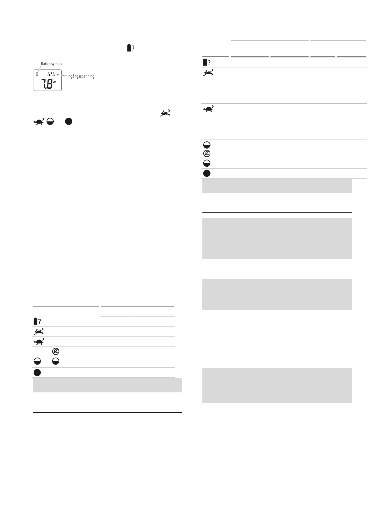
19
Endast aggregat 12000i, X12i, 412i, 6000i, 6000i-EU, X6i,
X6i-EU, 406i och 406i-EU
När väljaromkopplaren ställs in på Batteritest visar LCD-displayen
också ingångsmatarspänningen.
När spänningen ligger utanför det normala området (under 11,8 eller
över 17 V) blinkar batterisymbolen.
Under normal användning, när väljaromkopplaren ställs in på ,
, eller , om batterispänningen är dålig, blinkar
batterisymbolen på LCD-displayen. Ladda batteriet genast.
Val av batteri och hantering
Det här avsnittet avser enbart 12 V återuppladdningsbara batterier.
De batterier som du väljer beror på om din installation är en soldriven
installation eller en som enbart drivs med batteri. För båda typer av
installationer kommer den väljarbrytarposition som du oftast väljer vara
en faktor. Se vidare i
Användning
på sidan 17 för en förklaring av hur
väljarbrytaren fungerar.
Välja batteri för installation enbart med batteri
Som en hjälp visas amp hour-värdet (Ah) för det 12 V
återuppladdningsbara batteriet nedan. Denna tabell baseras på en
driftperiod på 21 dagar mellan batteriladdningarna. Även om
användningstiden kan överskrida 21 dagar är det troligt att detta
orsakar skada på batteriet, vilket för med sig att batteriet måste bytas
ut oftare. För att systemet ska fungera så pålitligt som möjligt och
batteriet hålla länge är det bästa att använda ett 12 V
återuppladdningsbart batteri och att ladda upp det när det är halvtomt.
För mer information om hur batterispänning kontrolleras, se
Test av
batteriets spänning
på sidan 18.
Väljaromkopplarens position
Rekommenderade batterier
6 J-modeller 12 J-modeller
450 Ah 700 Ah
575 Ah 900 Ah
575 Ah 900 Ah
eller
370 Ah 600 Ah
700 Ah 1100 Ah
Varning!
12 V återuppladdningsbara batterier måste användas.
Välja batteri för en solpanelsinstallation
Batteriet och solpanelerna måste väljas med omsorg för att passa
aggregatets elektriska strömförbrukning. Liksom positionen för
väljaromkopplarens position kommer batteriet och solpanelerna du
väljer att bero på hur mycket solsken platsen för installationen utsätts
för.
Som en hjälp visas amp hour-värdet (Ah) för det 12 V
återuppladdningsbara batteriet nedan. Tabellen visar batterikraven för
upp till sju dagars drift med lite eller inget solljus. Den tar med olika
solpanels- och regulatortyper i beräkningen som skulle kunna användas
i solpanelsinstallationen. För mer detaljerad information, se
www.tru-test.com.
Väljarom-
kopplarens
position
Ström som krävs
(ungefärlig)
Minsta batterikapacitet
(80 % urladdning)
6 J-
modeller
12 J-
modeller
6 J-
modeller
12 J-
modeller
410 mA 700 mA 110 Ah 190 Ah
410 mA (dag)
650 mA (natt)
530 mA (24
timmars
genomsnitt)
700 mA (dag)
1 100 mA (natt)
900 mA (24
timmars
genomsnitt)
140 Ah 240 Ah
650 mA (dag)
410 mA (natt)
530 mA (24
timmars
genomsnitt)
1 100 mA (dag)
700 mA (natt)
900 mA (24
timmars
genomsnitt)
140 Ah 240 Ah
eller 330 mA 580 mA 85 Ah 150 Ah
650 mA 1 100 mA 170 Ah 290 Ah
Varning!
12 V återuppladdningsbara batterier måste användas.
Batterihantering
Varning!
Batterier innehåller skadliga kemikalier och om de
används på ett felaktigt sätt kan de orsaka skada. Observera
riktlinjerna för hur batteriet ska skötas, underhållas och om
batterisäkerhet i den här bruksanvisningen och i dokumentation
som medföljer batteriet.
Batteriladdning
Varning!
-Försök inte återuppladda ett icke-återuppladdningsbart batteri.
-När ett batteri återuppladdas, försäkra dig om att det finns
tillräcklig ventilation så att gaser kan avvika.
Det är viktigt med regelbunden återuppladdning av batteriet. Använd
en säkerhetsgodkänd batteriladdare och läs igenom batteritillverkarens
rekommendationer.
1Fäst fast den positiva (+) batteriladdarledningen till den positiva
sidan på batteriet och den negativa (-) batteriladdarledningen till
den negativa sidan på batteriet.
2Anslut batteriladdarens ingångsströmkontakt till ett nät- eller
ledningsuttag och sätt på strömmen.
Varning!
Om batteriet överladdas reduceras dess livslängd.
Överskrid inte rekommendationerna från batteritillverkaren
avseende återuppladdning av batteriet från en nätdriven
(ledningsdriven) källa.
Batteriskötsel och -underhåll
•Placera batteriet i en lämpligt utformad batterilåda om batteriet
kan komma att utsättas för väderväxlingar.
•När batteriet inte används ska det förvaras fulladdat och
återuppladdas regelbundet (var 8:e vecka).
•Återuppladda ett urladdat batteri så snart som möjligt. Batteriet
får inte lämnas urladdat.
•Undersök batteriet regelbundet för att kontrollera att
elektrolytnivån inte sjunker under ytan på batteriplattorna.
•Fyll på batteriet med destillerat vatten. Fyll inte på för mycket. Se
vidare i batteritillverkarens rekommendationer för mer
information.

20
Batterisäkerhet
•Försäkra dig om att batteriet ventileras väl när det återuppladdas.
•Undvik temperaturer över 50°C.
•Försäkra dig om att batteriet inte utsätts för öppna flammor eller
gnistor.
Använda en fjärrkontrollerad handenhet
Aggregat 12000i, X12i, 412i, 6000i, 6000i-EU, X6i, X6i-EU, 406i, och
406i-EU tar emot kommandon från en fjärrkontrollerad handenhet från
Tru-Test. Ingen konfigurering krävs. Aggregatet och fjärrkontrollen har
förprogrammerats för kommunikation.
OBS:
Aggregat 6000, 6000-EU, X6, X6-EU, 406 och 406-EU kan inte
användas med en fjärrkontrollerad handenhet.
Aktivera aggregatet för användning med en
fjärrkontrollerad handenhet
Under de första 10 minuterna i drift kan aggregatets
fjärrkontrollfunktion aktiveras. Under denna period blinkar den stora
pilen på LCD-displayen för att indikera detta. Aggregatet fungerar
annars normalt.
För att aktivera fjärrkontrollfunktionen, stäng av aggregatet med den
fjärrkontrollerade handenheten (se handboken för den
fjärrkontrollerade handenheten för detaljer). Aggregatet slutar pulsera
och den sista gröna lampan kommer att blinka för att indikera att
aggregatet befinner sig i Beredskapsläge. Den stora pilen på LCD:n
fortsätter att lysa för att indikera att aktiveringen har genomförts.
När aggregatets fjärrkontrollerade handenhet har aktiverats behöver du
inte genomföra aktiveringsproceduren igen.
OBS:
-Om aggregatet inte aktiveras inom de första 10 minuterna det
används måste du stänga av aggregatet innan du kan försöka på
nytt.
-Du kan avaktivera fjärrkontrollsfunktionen när som helst. För
instruktioner, se handboken för den fjärrkontrollerade
handenheten. Om du inte har en fjärrkontrollerad handenhet, ta
aggregatet till en auktoriserad serviceverkstad för att avaktivera
funktionen.
Den fjärrkontrollerade handenheten
Den fjärrkontrollerade handenheten är tre redskap i ett. Den fungerar
som en:
•Fjärrkontroll – Sätter på och stänger av aggregatet från en plats
var som helst på elstängslet.
•Felsökare – Hjälper till att hitta fel var som helst på
stängselsystemet.
•Voltmätare/Ammätare – Ger omedelbar feedback om stängslets
prestanda (spänning och strömstyrka)
För detaljerade instruktioner om hur den fjärrkontrollerade handenheten
används, se vidare i bruksanvisningen som medföljer handenheten.
Alternativt kan den senaste kopian av bruksanvisningen laddas ner från
www.trutest.com.
Varning!
Aggregatet återaktiveras efter ett strömavbrott även om
det stängdes av av den fjärrkontrollerade handenheten innan
strömavbrottet. Stängslet måste alltid anses vara strömförande,
oavsett aggregatets omkopplarposition eller fjärrkontrollens status.
Om du arbetar på ett stängselavsnitt, isolera avsnittet med en
strömbrytare eller koppla bort aggregatet från strömkällan.
Att bygga ett permanent elstängsel
Komponenter i ett elstängsel
Ett elstängselsystem omfattar följande delar:
•
Ett aggregat.
•
Ett jordledningssystem.
Detta innehåller ett antal metallstavar
nedstuckna i jorden, som är anslutna till jordningsuttaget på
aggregatet.
•
Isolerade underjordskablar.
Elektriska stängsel täckta med isoleras
plast, lämpliga för användning underjord eller genom väggar.
Används till att ansluta aggregatet till jordledningen och stängsel.
•
Ett isolerat stängsel.
Anslutet till aggregatets stängseluttag.
Stängsel kan vara tillverkade i många utföranden (se nedan).
Andra användningsbara komponenter kan läggas till:
Frånslagsbrytare. Installerade i regelbundna intervaller ger
dessa möjlighet att isolera sektioner av stängslet för
reparation.
Åskavledarsats. Används för att minska skadan på aggregatet
från blixtnedslag som leds nedåt stängselledningen.
Typisk installation
Djuret får en stöt när en krets sluts mellan stängslet och
jordledningssystemet. Stängslet nedan har spänningsförande ledningar
och kräver fuktig jord (alltså med god ledningsförmåga). Dessa
stängseltyper kallas ibland “spänningsförande” eller “med återgång
genom jord”.
Alternativ installation
Till jordar med låg ledningsförmåga (torra eller sandiga)
rekommenderas ett system av typen ‘återgång genom stängslet’ eller
‘återgång genom jordledningen’. Med den här typen av stängsel är
stängslets jordningsuttag anslutet direkt till minst en ej elektrifierande
stängselledning (jordledning). Djuret får en maximal stöt vid beröring
med en spänningsförande ledning och jordledning samtidigt.
Bipolär installation
I områden med svaga jordningsförhållanden kan en “bipolär”
installation användas för att förbättra stängslets prestanda. Med en
bipolär installation är alla stängseltrådar isolerade. Alternerade
stängseltrådar är sammanlänkade för att forma en negativt laddad krets
och en positivt laddad krets. Aggregatet skickar vidare halva
utgångsspänningen till de negativt laddade trådarna och halva
utgångsspänningen till de positivt laddade trådarna. Djuren får en stöt
vid beröring med en positiv tråd eller en negativ tråd, ELLER om det
kommer i beröring med både en positiv och negativ tråd samtidigt, får
de en kraftigare stöt.
This manual suits for next models
14
Table of contents
Languages:
Other Tru-Test Power Supply manuals


