True & Paramount XFT-100 User manual
XFT-100
F
UNCTIONAL
T
RAINER
A
SSEMBLY
M
ANUAL
AM-XFT-100

2
A MESSAGE TO OUR CUSTOMERS
Thank you for your purchase ofthe Paramount Fitness XFT-100 Functional Trainer. Because of the
many unique features included inthis machine, this manual was created to provide you with
information on how to properly install and maintain your equipment. Proper maintenance will
ensure that your newequipment will last for years.
For your convenience, product questions can be answered byan Authorized Paramount Dealer
orby contacting a TRUE Fitness Customer Service Representative at:
1-800-883-8783 or 1-800-721-2121
Office hours are Monday-Friday, 8:00am - 5:00pm CST
Thank You for your patronage.
TRUE Fitness
865 Hoff Road
O'Fallon, MO 63366
IMPORTANT
REVIEW THE GENERAL MAINTENANCE MANUAL FOR IMPORTANT SAFETY AND
MAINTENANCE TIPS. THE MANUAL HAS BEEN INCLUDED WITH YOUR MACHINE ORDER
AND CAN ALSO BEDOWNLOADED FROM OUR WEBSITE AT:
http://www.truefitness.com
PLEASE RETAIN THIS MANUAL FOR FUTURE REFERENCE.

3
S
AFETY
.......................................................................................................................................... 4
G
ENERAL
C
ARE
AND
M
AINTENANCE
................................................................................................. 5
M
ACHINE
S
PECIFICATIONS
.............................................................................................................. 6
P
REPARATION
................................................................................................................................7
C
ARTON
C
ONTENTS
........................................................................................................................ 8
S
TEP
1: A
SSEMBLE
T
HE
A
DJUSTMENT
D
ISCS
.................................................................................... 10
S
TEP
2: A
SSEMBLE
THE
F
OOT
E
XTENSIONS
....................................................................................... 11
S
TEP
3: A
SSEMBLE
THE
C
ROSS
B
RACES
........................................................................................... 12
S
TEP
4: A
SSEMBLE
THE
W
EIGHT
P
LATES
.......................................................................................... 13
S
TEP
5: A
TTACH
THE
W
EIGHT
S
TACK
L
ABELS
.................................................................................... 14
C
ABLE
R
OUTING
D
IAGRAM
.............................................................................................................. 15
M
ACHINE
L
ABELS
........................................................................................................................... 16
S
ERVICE
........................................................................................................................................ 17
P
ARTS
D
IAGRAMS
.......................................................................................................................... 18
W
ARRANTY
..................................................................................................................................... 27
TABLE OF CONTENTS

4
SAFETY
1. Review and understand all of the warning labels affixed to this machine and on the facility safety sign.
Replace any warning label at first sign of wear. Labels and the Facility Safety Sign may be obtained from
Paramount free of charge.
2. Be certain that the machine operation is understood before it is used. Refer to the instructional Procedure
Label provided with the machine. Use only for the intended exercise. DO NOT invent or perform exercises
not included on the Instructional Procedure Label. DO NOT modify the machine.
3. Keep children away from this equipment. Supervise use by teenagers.
4. It is recommended that users receive a thorough medical exam before commencing an exercise program.
All medical issues should be reviewed to ensure that weight training will not aggravate pre-existing
medical conditions.
5. Check the function of your machine daily by verifying the following:
• Cables and end fittings are intact.
• All adjustments are possible and carried out with ease.
• The proper selector pin is in the weight stack.
• The exercise is performed smoothly, free of noise and/or binding.
• If the machine appears damaged or inoperable, DO NOT USE until it is repaired. Only use Paramount
supplied components to service this machine.
6. Instruct Users not to wear loose or dangling clothes or have headphone wire hanging when using this
equipment.
7. Instruct Users not to use the cable end fittings as a handle or means of performing an exercise. Only use
Paramount provided handles or attachments, properly connected to the cable end.
8. DO NOT ALLOW users to use straps, resistance bands or other means to do stretching or body weight
exercises from the framework of this machine.
9. Cables: Inspect the entire cable weekly and the end fittings daily. Pay close attention to the area going
over pulleys and to the end connections. Replace all cables at first signs of wear and on an annual basis.
Use only Paramount supplied replacement cables.
10. Nuts, Bolts, and Fasteners: Check tightness weekly. If any hardware has become loose, retighten and/or
use Loctite
™
Threadlocker 242.
11. Use ONLY Paramount weight selector pins. Other manufacturer’s pins may work free of the weight stack
causing possible injury. Be certain the pin is completely inserted prior to use.
12. DO NOT high-pin or double-pin the weight stack. DO NOT allow the machine to be used if the top plate or
weight stack is pinned in a raised position. Use an assistant and carefully return the machine to the
proper position with the cap plate resting on the top weight. Inspect the cable to ensure that it is seated in
all of the pulleys.
13.Use ONLY the Paramount adder weight system specifically designed for this machine.
14. DO NOT attempt to free any jammed assemblies by yourself as this may cause injury.
15. Adjustment Pins: check the function of the position selector pins on the adjustable arms. Make sure that
the selector pin inserts completely into each position without binding.
16. Frames and Lifting Arms: Inspect weekly for integrity and function. Replace any component at first signs
of wear. Use only Paramount supplied components.
17. Follow the installation guidelines provided with the products.
18.The Maximum user weight for this equipment is 300 lbs. (136 kg.)
19. Retain these instructions for future reference.
20. If you have any questions, do not hesitate to contact your Paramount dealer or Paramount Fitness Corp.
at (800)721-2121 or (323) 721-2121 or nasales@paramountfitness.com.
21. Refer to Maintenance Schedule label on the machine and this manual for when to perform maintenance.

5
GENERAL CARE AND MAINTENANCE
IMPORTANT
Preventative maintenance is crucial to maintaining the function and safety of this equipment. Your
facility MUST establish written guidelines for preventative maintenance and keep written or online
records of the maintenance performed on these products. As a minimum, the items presented in
the SAFETY section of this document and the items that follow here, should be included in your
maintenance program. Be certain that you use only Paramount provided replacement parts when
servicing this equipment.
1. Cable Ends: Inspect end fittings daily for wear. Replace cables at the first sign of wear and on an
annual basis. Be certain that the cable locking nut is tight at threaded cable fitting connections.
2. Nuts, Bolts, and Fasteners: Check tightness weekly. If any hardware has become loose, retighten
and/or use Loctite
TM
brand Threadlocker 242.
3. Frames: Wipe all machines down with a damp cloth and dry completely each day. This includes
painted parts, chrome parts and upholstered pads.
4. Painted and chrome plated parts: Use Simple Green or similar cleaner for light dirt and grime. Use
Turtle Wax Polishing Compound or a good car polish to remove heavier dirt and grease as well as
for polishing. DO NOT use solvents, lacquer thinner, acetone or finger nail polish remover. For
scuffs and marks that are not removed by the above methods use a soft scrub cleanser. Make
sure all parts are dry upon completion.
5. Weight stack enclosures (shrouds): Wipe down with a damp cloth as needed.
6. Exercise instruction labels: Clean with soap and water as needed.
7. Guide rods: Wipe all dirt and dust from the guide rods before applying a light application of Tri-
Flow
TM
or other teflon spray lubricant. Spray the Tri-Flow
TM
on a rag and then wipe the guide rods
with the rag. DO NOT use oil lubricants such as WD-40. Caution: Tri-Flow
TM
will stain carpet and
clothing.
8. Bronze bushings: Check monthly for signs of wear and replace as needed. Lubricate monthly with
Tri-Flow
TM
.
9. Please refer to the General Maintenance Manual (part number: AM-GMM) for other important
safety and maintenance information.
10. Be sure all hardware is tight before using the machine.
11. When replacing any component, use only Paramount supplied parts.
I
NSTALLATION
G
UIDELINES
• DO NOT install any fitness equipment near a pool, hot tub or other damp locations. Corrosion
caused by installation in these locations can lead to premature failure of components.
• If the machine is placed in an open room, leave at least 2 feet [60 cm] of clearance around the
machine.
• Install the machine on a solid, level surface as defined and required by local building and
architectural codes.
• This machine has provisions to allow it to be anchored to the floor. If you choose to anchor it to
the floor, consult a qualified, licensed contractor to perform the installation due to the wide
variation of flooring available. Use a fastener system that will provide a minimum of 500 lbs of
pull out force using 3/8” hardware.

6
F
EATURES
• Two 130lb. [59 kg.] fully independent weight stacks.
• The cable/pulley arrangement on this machine provides a 2:1 weight reduction. This
means that the handle pull force required to raise the entire 130 lb. weight stack is
actually 65 lb. The advantage of this for functional training is that the weight stack has
1/2 the momentum and 2 times the cable travel of a conventional 1:1 ratio machine.
Lower weight stack momentum translates to smoother and more consistent resistance
feel when performing burst or ballistic movements.
• (12) weight stack settings. Pull force increments are 5.0lbs [2.3 kg].
• 65 lb. [29.5 kg.] max resistance at cable end (per handle).
• Cable travel is 6.4 feet (77 inches)[194 cm.] per handle.
• Machine weight = 553 lbs. [251 kg.]
• Floor loading = 44 lbs/ft
2
[211 kg/m
2
]
• 20 vertical arm adjustments labeled “A” through “T”.
• 14 horizontal arm adjustments labeled “1” through “14”
MACHINE SPECIFICATIONS
LQ
FP
LQ
FP
LQ
FP
$UPV2XW
$UPV,Q
LQ
FP
LQ
FP
LQ
FP
LQ
FP
*Max height shown with standard chin-up bar. For low ceiling applications (under 84”),
order optional cross brace XFT100-CBR200ALT to replace chin-up bar.
*

7
REQUIRED TOOLS
CARTONS REQUIREMENTS
Your XFT-100 is shipped partially assembled in 2 main cartons. Carton 1 contains the right side
frame and Carton 2 contains the left side frame.
Each machine requires (6) boxes of weight plates, (3) boxes per weight stack. Each box contains
four 10 lb. weight plates.
It is strongly recommended that at least two people are used to assemble this machine.
Ratchet Handle
Socket Extension, (8” or longer)
note: 2 or more shorter extensions may be used to
achieve the necessary length for assembly.
Hex Bit Sockets
-7/32” (or 5.5mm)
-5/16” (or 8mm)
9/16” Socket or 9/16” wrench
Allen wrench (supplied with unit):
- 1/8”
- 7/32” (or 5.5 mm)
Plastic or Rubber Mallet
Step ladder (highly recommended)
or
10 LB. Weight Plate Box
Part Number: B1602 Comprised
of
(4) x 10 lb. Weight Plates
LEFT SIDE RIGHT SIDE
PREPARATION

8
CARTON CONTENTS
I
TEM
P
ART
N
UMBER
D
ESCRIPTION
Q
TY
.
1 XFT100-HFA000X FRAME ASSEMBLY, RIGHT SIDE 1
2 XFT100-CBR000X CROSS BRACE, LOWER 1
3 XFT100-CBR100X CROSS BRACE, UPPER 1
4 XFT100-MFR200X FOOT EXTENSION, RIGHT SIDE 1
5 XFT100-ADJ000X ADJUSTMENT DISC, RIGHT 1
6 XFT100-HW HARDWARE BOX 1
CARTON 1 (XFT100-CTN1)
1
3
26
4
CARTON 2 (XFT100-CTN2)
I
TEM
P
ART
N
UMBER
D
ESCRIPTION
Q
TY
.
1 XFT100-HFA100X FRAME ASSEMBLY, LEFT SIDE 1
2 XFT100-CBR200 CHIN UP BAR 1
3 XFT100-MFR300X FOOT EXTENSION, LEFT SIDE 1
4 XFT100-ADJ100X ADJUSTMENT DISC, LEFT 1
1
2
3
5
4

9
CARTON CONTENTS
H
ARDWARE
B
OX
C
ONTENTS
(XFT100-HW)
OPTIONAL ACCESSORY KIT
An optional accessory kit is available for your XFT-100 Functional Trainer, part #XFT-100-ACC-KIT.
An assortment of handles and cable attachments are included to allow users to perform more
diverse exercises and target specific muscles and movements more completely.
OPTIONAL ADDER WEIGHT KIT
An optional adder weight kit is available for this machine. The kit contains (2) 5 lb. adder weights,
each of which will provide 2.5 lbs. of resistance at the handle. Part number is XFT-100-ADR.
P
ART
N
UMBER
D
ESCRIPTION
Q
TY
.
C 624 Socket Head Screw, 3/8”-16 x 1-1/4” 4
C 657ZP Flat Head Screw, 3/8”-16 x 3/4”, ZINC 8
C 659ZP Flat Head Screw, 3/8”-16 x 1-1/4”, ZINC 4
C 678ZP Button Head Screw, 3/8”-16 x 1”, ZINC 8
C 749 Split Lock Washer, 3/8” 12
C 754C Flat Washer, 3/8” 16
C 766A Lock Nut, 3/8-16, low height 8
IT90013800 End Plug, 50 x 100 Oval 2
LBL-WSEM-01065 Label, Weight Stack, 12 position, 65 lbs
with 29.5 kg.
2
B1005 Carabiner, snap link 2
B1110A Strap Handle, molded with logo 2
10
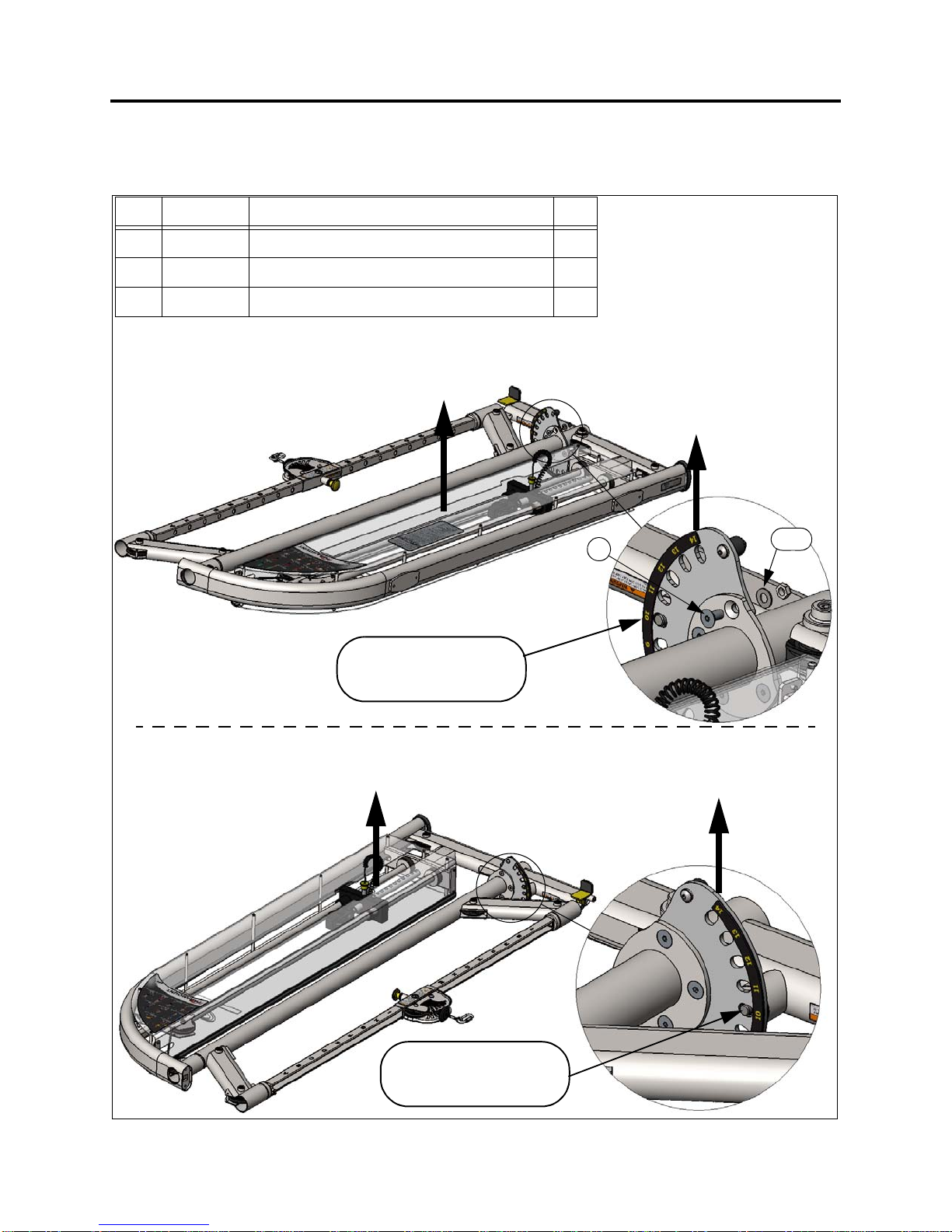
The lower adjustment discs can be assembled while the unit is still horizontal in the box. This will
make it easier to handle the frame assembly when it is out of the box.
STEP 1: ASSEMBLE ADJUSTMENT DISCS
I
TEM
P
ART
#D
ESCRIPTION
Q
TY
.
1 C 657ZP Flat Head Screw, 3/8”-16 x 3/4”, ZINC 8
2 C 754C Flat Washer, 3/8” 8
3 C 766A Lock Nut, 3/8-16, low height 8
12, 3
#14 on Adjustment
LEFT SIDE FRAME
CARTON 2
Weight Stack Shroud
Opening facing UP.
Disc facing UP.
Place Adjustment Pin
in position #10 on the
Adjustment Disc.
RIGHT SIDE FRAME
CARTON 1
#14 on Adjustment
Disc facing UP.
Weight Stack Shroud
Opening facing UP.
Place Adjustment Pin
in position #10 on the
Adjustment Disc.
PROPER ORIENTATION!
PROPER ORIENTATION!
PROPER ORIENTATION!
PROPER ORIENTATION!

11
1. Assemble the base frame FOOT
EXTENSIONS on the Right and Left
Side frames as shown.
Align the edges of the tubes and
fully tighten hardware.
STEP 2: ASSEMBLE FOOT EXTENSIONS
I
TEM
P
ART
#D
ESCRIPTION
Q
TY
.
1 C 749 Split Lock Washer, 3/8” 4
2 C 624 Socket Head Screw, 3/8”-16 x 1-1/4” 4
12
NOTE CUT-OUT IN TUBE
FOR PEDAL CLEARANCE
8” Long Extension
with 5/16” Hex Bit
RIGHT SIDE FRAME
RIGHT FOOT EXTENSION
LEFT SIDE FRAME
LEFT FOOT EXTENSION

12
1. Assemble the upper and lower cross braces as shown. Note that the upper cross brace has
accessory hooks on the front. Loosely assemble the hardware, DO NOT TIGHTEN!
2. Assemble the Chin-up bar and loosely assemble the hardware.
3. Verify that all (4) feet of the machine are sitting on the floor. Incrementally tighten the hardware
on all of the braces and chin-up bar.
4. Assemble the end plugs into the foot extension tubes.
STEP 3: ASSEMBLE THE CROSS BRACES
I
TEM
P
ART
#D
ESCRIPTION
Q
TY
.
1 C 659ZP Flat Head Screw, 3/8”-16 x 1-1/4”, ZINC 4
2 C 754C Flat Washer, 3/8” 8
3 C 749 Split Lock Washer, 3/8” 8
4 C 678ZP Button Head Screw, 3/8”-16 x 1”, ZINC 8
1
2, 3, 4
2, 3, 4 LOWER CROSS BRACE
UPPER CROSS BRACE
CHIN-UP BAR
END PLUG
13
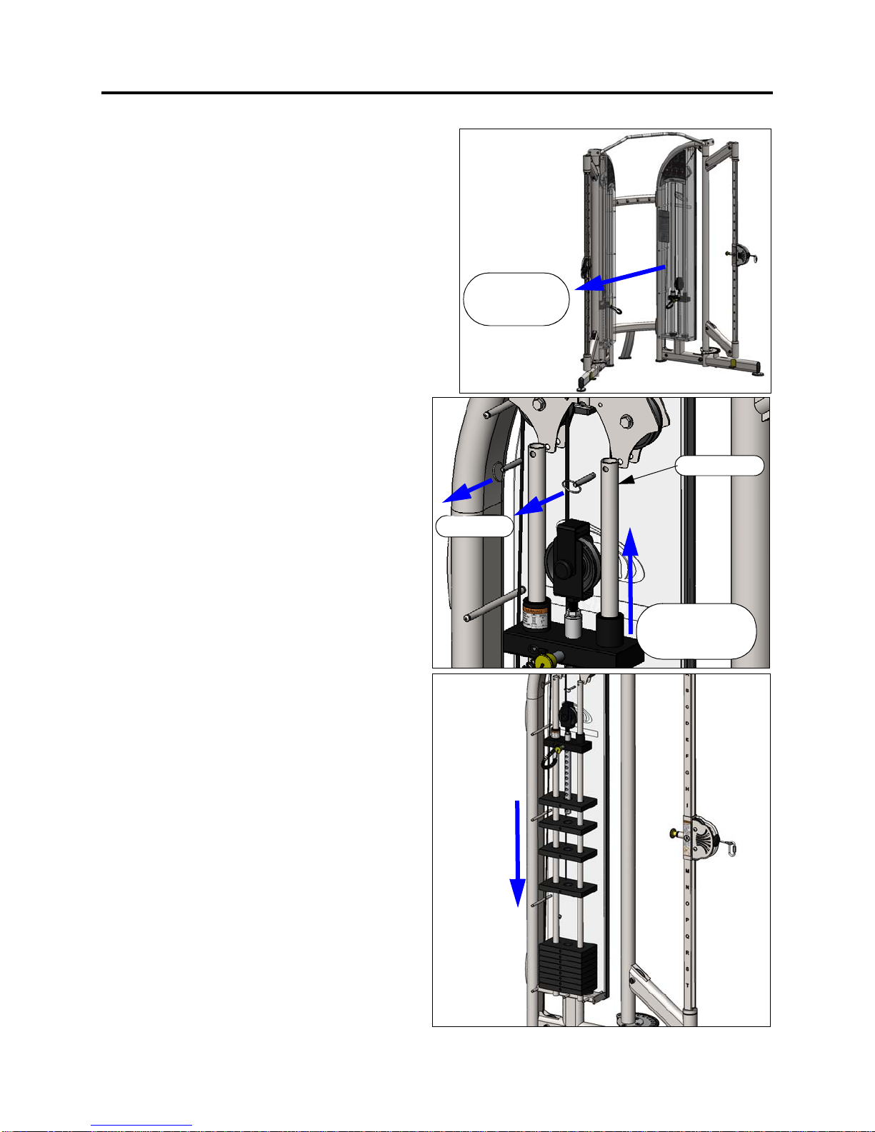
1. The machine should be in its final position.
Depending upon the space surrounding your
machine, either the front or rear shrouds will need
to be removed to install the weight plates. These
instructions will show weight plate installation
with the front shroud removed.
2. Remove the screws securing the front shrouds
(12 per shroud). Lay the shroud down on a flat
surface. DO NOT STAND it up against a wall as it
can easily slide and become damaged.
3. Pull the pins holding the guide rods in place.
4. Tilt the guide rods to the side then forward
as shown.
5. Carefully slide the top plate/selector bar
assembly up and off of the guide rods.
NOTE: It is not necessary to remove the pulley
or cable from the top plate/selector bar
assembly. Have someone hold the top
plate/selector bar assembly to the side while
the weight plates are installed.
6. Install the weight plates, 12 plates per side.
7. Re-assemble the top plate/selector bar
making sure that the cable is not twisted.
8. Re-attach the guide rods to the frame with
the pull pins.
9. You can re-assemble the shroud now or
after you attach the weight plate labels as
shown on the following page.
STEP 4: ASSEMBLE THE WEIGHT PLATES
Remove
Front Shroud
Remove Top
Plate/Selector
Bar.
Pull Pins
Guide Rods
14
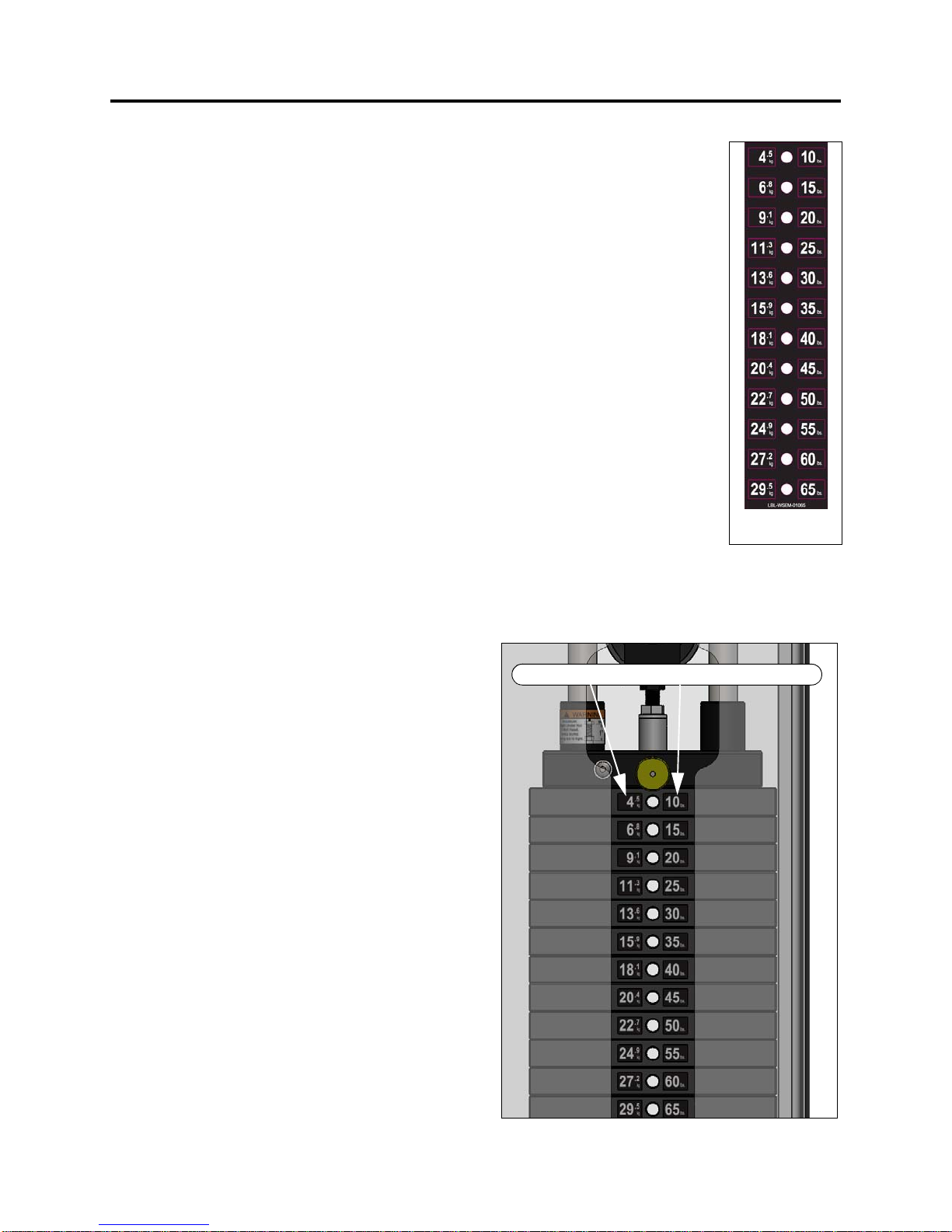
1. Verify that there are 12 weight plates installed on each stack.
2. Wipe the front surface of the weights, in the area that the label will be
installed, with isopropyl alcohol. Allow to dry completely before proceeding.
3. Shown to the right is the proper weight stack label for this machine. It contains
both LB and KG designations for each plate.
There are (3) options for installation.
A) Install just the LB labels.
B) Install just the KG labels
C) Install both the LB and KG labels.
NOTE that the designations on the label for each plate are the PULL
RESISTANCE at the handle and NOT the weight of the individual weight plates.
See the MACHINE SPECIFICATIONS section earlier in this manual for a brief
discussion on this.
4. The backing that covers the adhesive is cut in a series of vertical strips. If you
just want to install the LB stickers, only remove the backing strip directly
behind the area of the LB stickers. Likewise, if you intend to install the KG stickers, remove the
backing directly under the KG stickers. DO NOT REMOVE the backing from the area behind the
center section with the holes.
5. Carefully align the top hole in the label with the
hole in the top weight plate, then align the
bottom hole in the label with the hole in the
bottom weight plate.
6. Once the label is aligned, lightly press the
individual stickers into place. DO NOT rub the
area surrounding the individual labels.
7. Carefully press each sticker with your finger as
you peel away the surrounding material.
8. Once you are left with the individual stickers on
each plate, press and rub the sticker firmly to
the face of the plate.
9. Allow the adhesive to cure for 48 hours. DO NOT
attempt to “test” the integrity of the labels after
they have been installed.
10. The part number for the label sheet is LBL-
WSEM-01065.
STEP 5: ATTACH THE WEIGHT STACK LABELS
Attach KG stickers, LB stickers, or both.
LBL-WSEM-01065
PART NUMBER:

15
XFT-100 CABLE ROUTING DIAGRAM
Correct
ENSURE THAT THE CABLE
IS NOT ROUTED ON THE
OUTSIDE OF THE CABLE
RETAINER PIN. TYPICAL
ALL PULLEYS.
Wrong
Cable Retainer Pin
SCREW TO RETAIN
CABLE END.
REPLACE CABLES at the first sign of wear OR on an annual basis.
Part number: XFT100-CBL000X
16
If this machine is tobe installed in a
public use facility, ASTM F1749
requirements specify that the facility
sign shown tothe right is tobeinstalled
in plain view.
If you did not receive thefacility sign with
your order, youcan obtain one free of
charge bycalling 1-800-883-8783 or
1-800-721-2121.
BE ALERT!
THE FITNESS EQUIPMENT IN THIS FACILITY
PRESENTS HAZARDS WHICH, IF NOT AVOIDED,
COULD CAUSE SERIOUS INJURY OR DEATH.
PRIOR TO USING THE EQUIPMENT, READ THE WARNING LABELS
AND INSTRUCTION PLACARDS AFFIXED TO EACH MACHINE.
IF YOU ARE UNSURE ON HOW TO USE A MACHINE, SEEK THE
ASSISTANCE OF OUR FLOOR PERSONNEL. WE WILL BE HAPPY
TO INSTRUCT YOU ON HOW TO USE THE EQUIPMENT PROPERLY.
IMMEDIATELY REPORT ANY PIECE OF EQUIPMENT THAT IS NOT
FUNCTIONING PROPERLY TO OUR FLOOR PERSONNEL SO THAT
IT MAY BE EVALUATED AND SERVICED PROMPTLY.
DO NOT ATTEMPT TO USE OR FIX ANY PIECE OF EQUIPMENT
THAT IS NOT FUNCTIONING PROPERLY
ASTM F1749-96
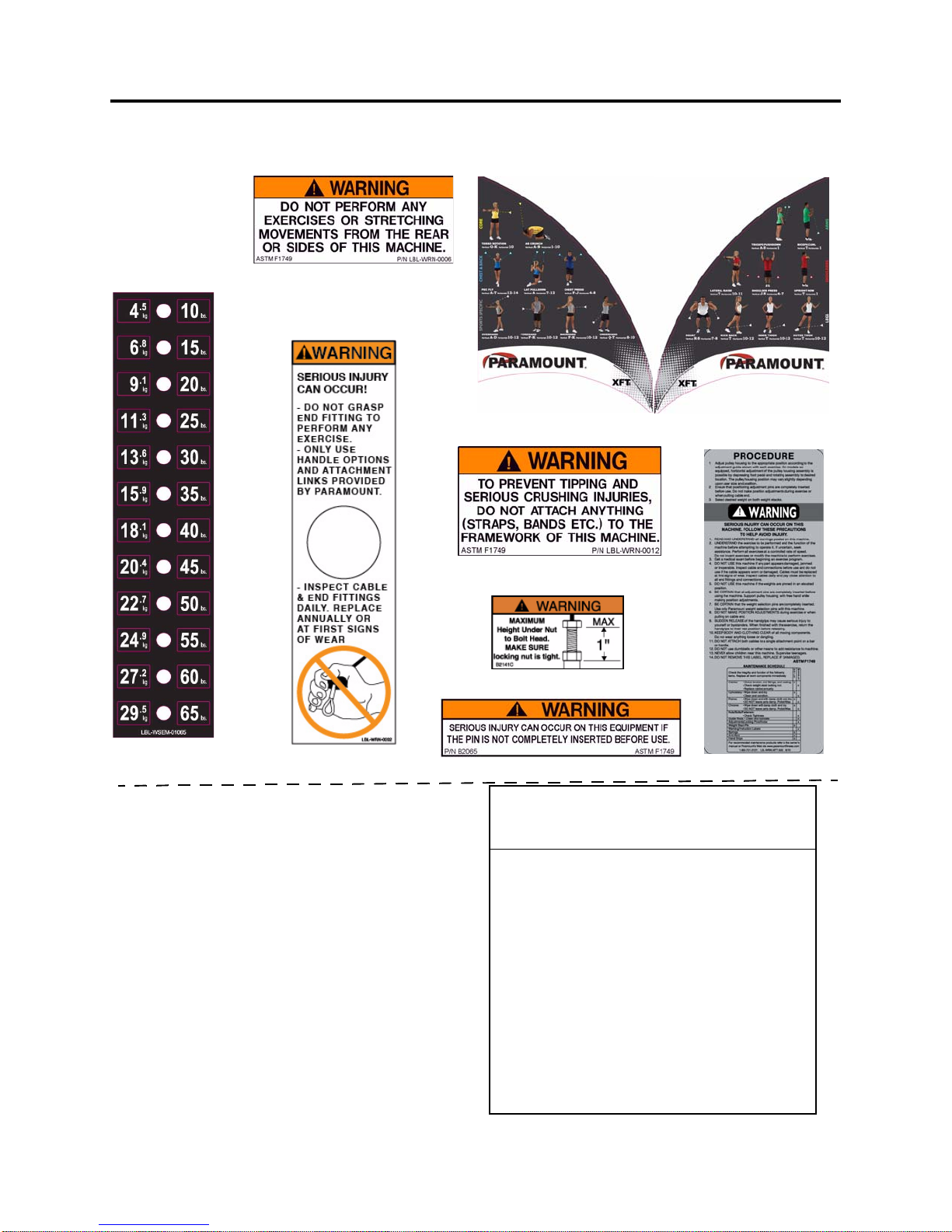
LBL--WSEM-01065
LBL-WRN-0202 B2065
LBL-PR-XFT100R
LBL-PR-XFT100L
(contains LB. & KG.)
LBL-WRN-XFT300
B2141C
LBL-WRN-0012
LBL-WRN-0006
MACHINE LABELS
The following are the Warning labels required for this XFT-100. If any of these labels are
missing or become damaged contact Paramount. Note: these labels are not to scale.
17
SERVICE
H
OW
TO
O
BTAIN
S
ERVICE
For warranty service, contact an Authorized Paramount Dealer or a TRUE Fitness Customer
Service representative at1-800-883-8783 or 1-800-721-2121. You can also email us at
Before you call, please havethe following information ready:
• Model Number: _______________________
• Serial Number: ________________________
• Date of Installation: ____________________
• A brief description of the problem
F
INAL
C
HECK
1. Verify that all hardware is tight.
2. If you haven’t already done so, lubricate all of the guide rods with a teflon spray lubricant.
Paramount recommends using TriFlow
TM
brand for excellent results.
3. On the vertical columns, verify that the adjustment pins can be fully engaged into each position (A
through T).
4. Depress the pedal and verify that the arm rotates through its full range of 180 degrees. Verify that
the adjustment pin fully engages into each position. Perform this procedure on both sides of the
machine.
5. Verify that the selector pin can be fully inserted into each weight plate.
6. Place the selector pin into the holder on the top plate/selector bar. Slowly pull the handle through
its full range of travel and let it retract. Verify that the cable moves freely, without any binding.
Repeat this procedure for the other side.
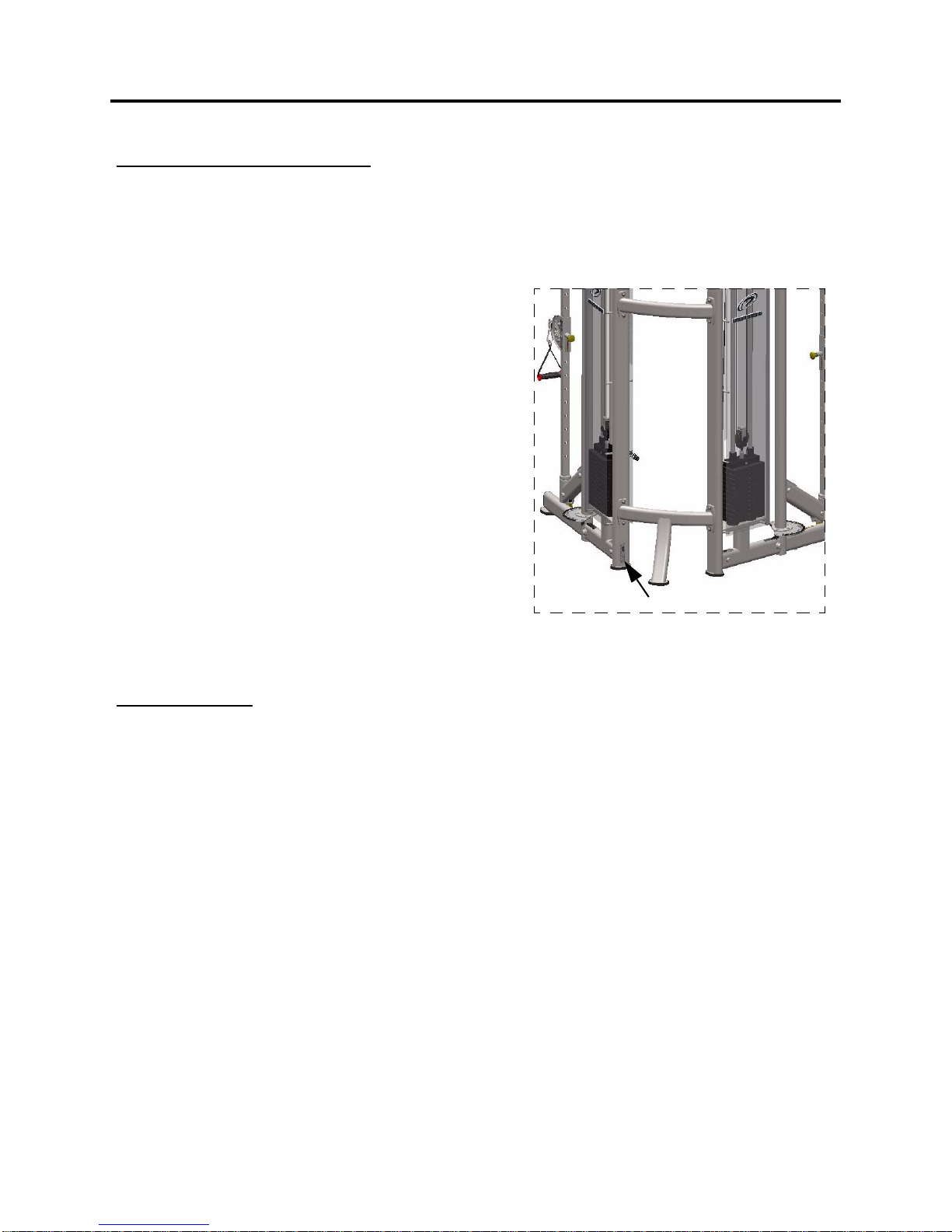
Serial Number
The serial number tag is located on the back of
the right upright.
XFT-100
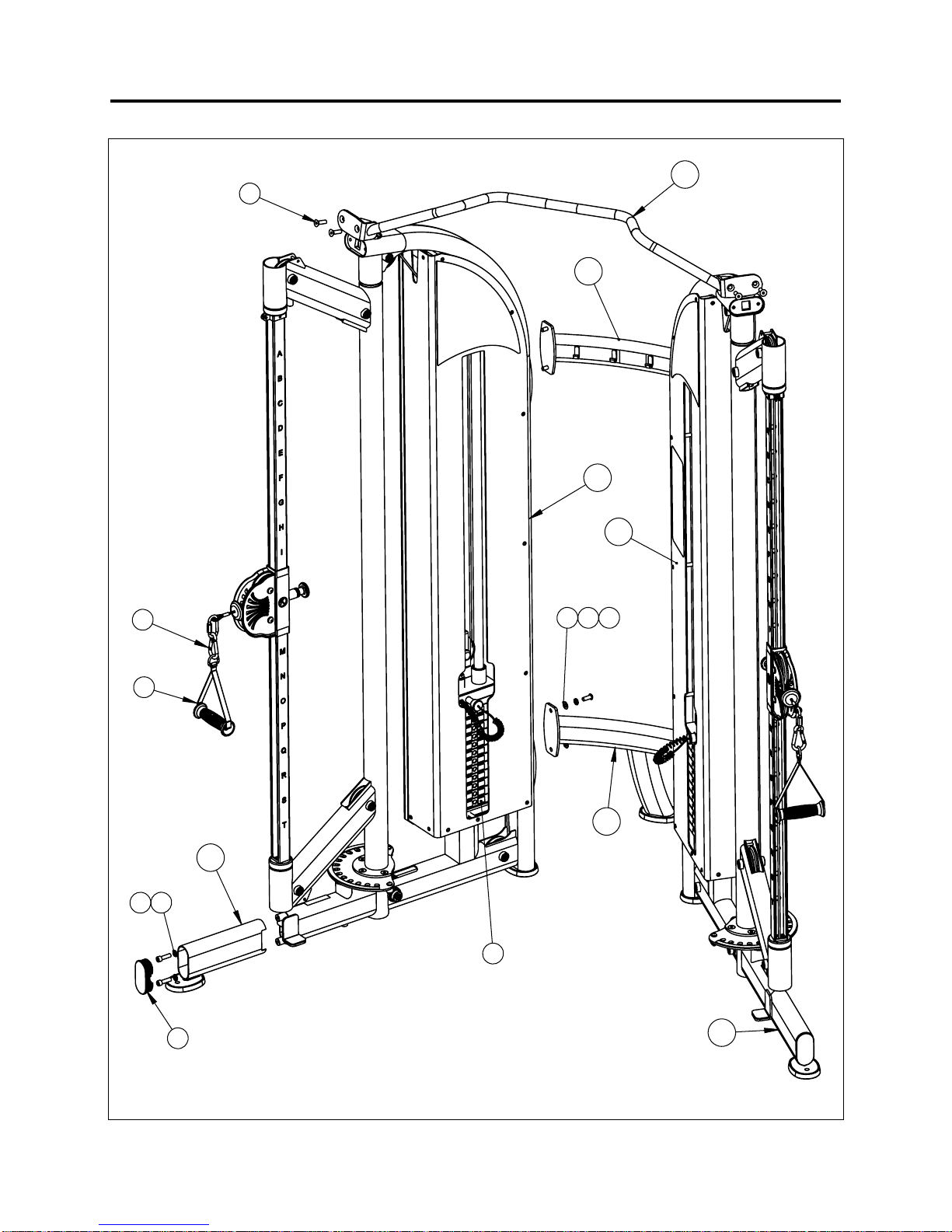
18
PARTS DIAGRAM

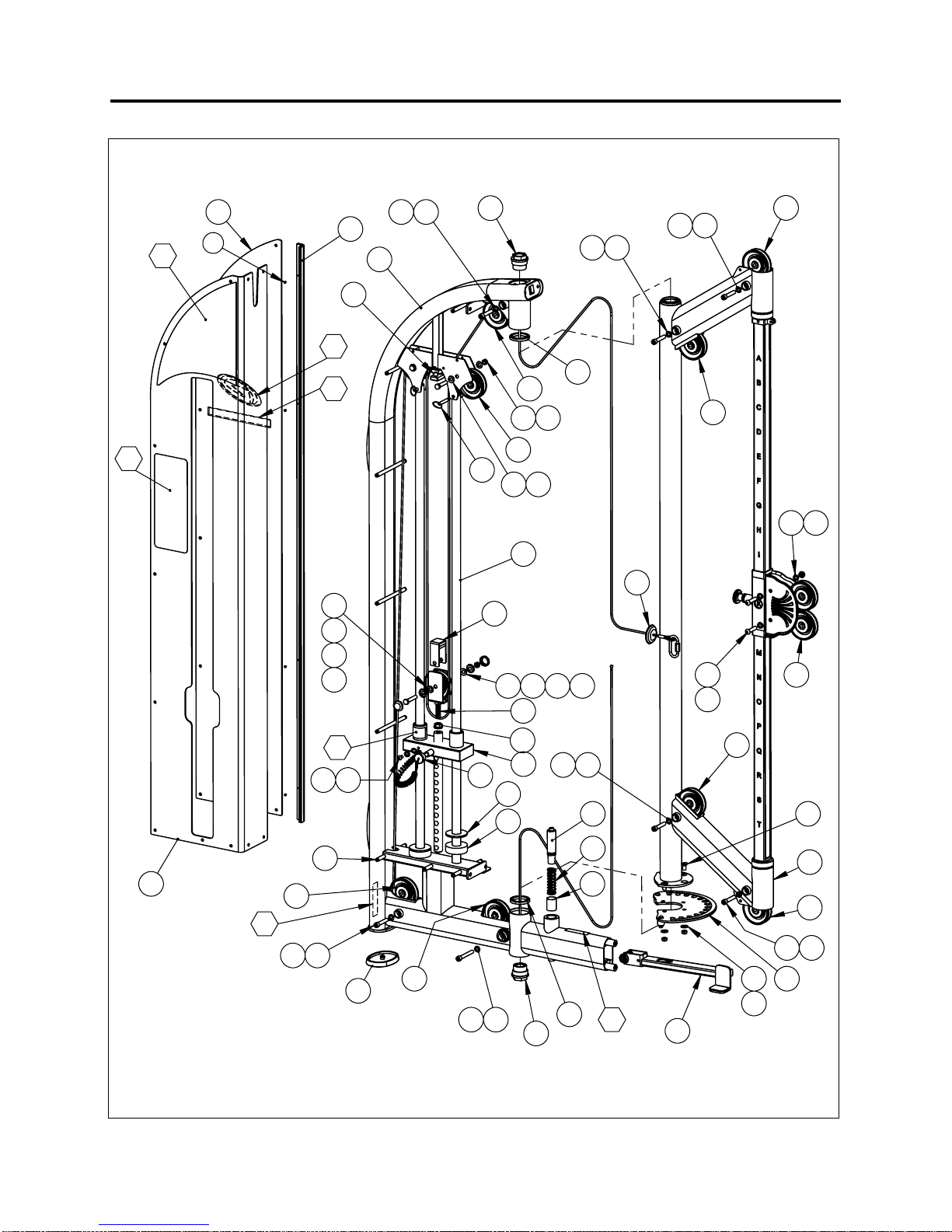
19
PARTS DIAGRAM
237,21$/833(5&5266%5$&(6+2:1$%29(,6$9$,/$%/(
725(3/$&(67$1'$5'&+,183%$5)25/2:&(,/,1*$33/,&$7,216
3$57180%(5
;)7&%5$/7
0$&+,1(+(,*+7:,7+67$1'$5'&+,183%$5,6
0$&+,1(+(,*+7:,7+237,21$/833(5&5266%5$&(,6
127()25/2:&(,/,1*$33/,&$7,216
,7(0
3$57180%(5
'(6&5,37,21
'HIDXOW47<
%
61$3+22.=,1&
%$ +$1'/(1</21675$3:,7+/2*2
&
6+6&5(:
&=3
)+6&5(:=,1&
&=3
%+6&5(:=,1&
&
/:0('63/,7/2&.:$6+(5
&&
):6$()/$7:$6+
,7
(1'3/8*;5$&(75$&.29$/
/%/:6(0
/$%(/:(,*+767$&.;/%.*
:(,*+767$&.
:(,*+767$&./%;3/$7(6
;)7&%5;
$66(0%/</2:(5&5266%5$&(
;)7&%5;
$66(0%/<833(5&5266%5$&(
;)7&%5
&+,183%$5
;)7+)$;
$66<)5$0(5,*+76,'(
;)7+)$;
$66<)5$0(/()76,'(
;)70)5;
$66<)227(;7(16,215,*+7
;)70)5;
$66<)227(;7(16,21/()7
20
PARTS DIAGRAM
$66(0%/<
;)7+)$;
5,*+76,'()5$0(
Table of contents
Other True & Paramount Home Gym manuals

Popular Home Gym manuals by other brands

RP3 Rowing
RP3 Rowing MODEL-T operating manual

Image Fitness
Image Fitness 312flat-incline Bench manual

NordicTrack
NordicTrack E8200 Competition Bench Manuel de l'utilisateur

Impex
Impex PHC -265 owner's manual

Bodymax Infiniti
Bodymax Infiniti R70I owner's manual

Northern Lights
Northern Lights NL-WCB Assembly instructions


