TOORX MSX50 User manual

Ed : Rev : Cod :
INSTRUCTION
08/18 GRLDTOORXMSX5000

•Free area shall be not less than 0.6m greater than the training area in the directions from which
the equipment is accessed. The free area must also include the area for emergency dismount.
Where equipment is positioned adjacent to each other the value of the free area may be shared.
Keep unsupervised children away from the equipment.
Safety Information

Note: Some of the smaller components may be pre-fitted to larger components. Please check carefully
before contacting us regarding any missing components.
Components - Parts
Please check you have all parts listed below
4

Note: Some of the smaller components may be pre-fitted to larger components. Please check carefully
before contacting us regarding any missing components.
Components - Parts
5
Please check you have all parts listed below

Note: The quantities below are the correct amount to complete the assembly. In some cases more
hardware may be supplied than is actually required. Someof thesmaller components may be pre-fittedto
thelargercomponents.
Components - Fixings
6
Please check you have all fixings listed below

Assembly instructions
Step 1
a. Insert the Guide rods (22#) into the holes of
the Rear stabilizer (2#). Fix them using 2 pcs
M10 x 25mm Allen bolts (37) and 2 pcs
Ø10mm Washers (44#).
b. Attach the Base frame (1#) to the Rear
stabilizer (2#). Secure them with 2 pcs M10x
70mm Carriage bolts (27#), the U-shape
bracket (104#), 2 pcs Ø10mm Washers (44#)
and 2 pcs M10 Aircraft nuts (46#).
Note:□50X1.5 End cap(56#), □38X1.5 End
cap(59#),□50 End cap(65#) were fixed in
the factory already.
7

Step 2
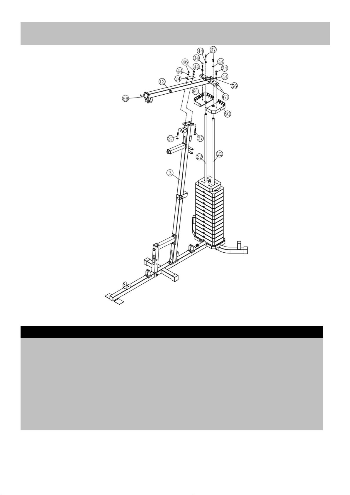
Attach the front vertical frame(3#) onto the
base frame(1#). Carefully align the holes and
secure them with 2 pc M10*70 carriage
bolt(27#), 1 pc bracket(24#),2pcs φ10
washers(44#) and 2pcs M10 Aircraft nuts(46#) .
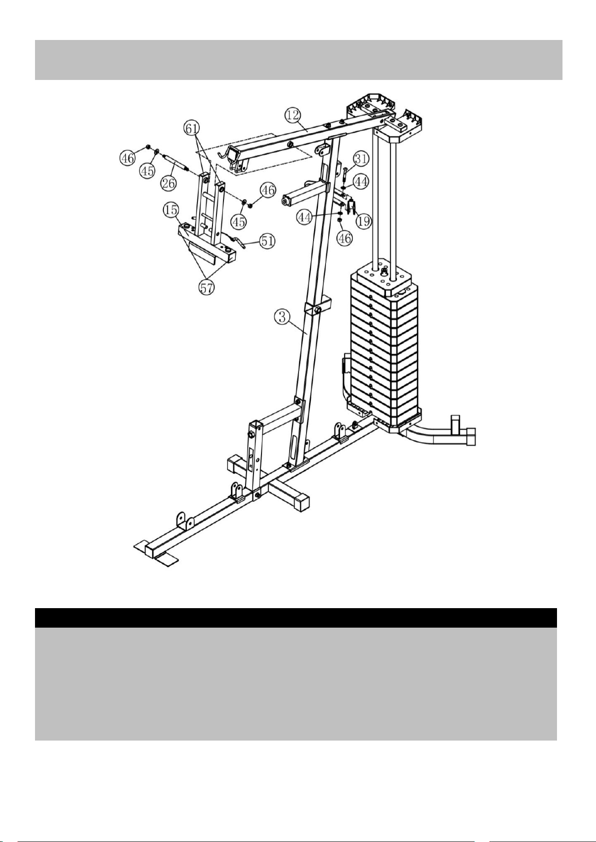
Attach one end of the seat pad support(6#) to
the front vertical frame(3#) and secure them
with 2pcs M10*70 Carriage bolt(27#),1pc
bracket(24#),2pcs φ10 washers(44#),2pcs
M10 Aircraft nuts(46#) .
Attach another end of the seat pad support(6#)
to the base frame(1#), Secure them with 1 pc
M10*70 Carriage bolt(27#),1pc φ10
washers(44#),1pc M10 Aircraft nuts(46#) .
note:□45X□38 Sleeve(68#), Rubber bumper(70#)
were fixed in the factory already.
Assembly instructions
8

9
Assembly instructions
Place 2pcs bottom weight stack cover
bracket along the guide rod and secure
them with 2pcs M10*25 Allen bolt (37#)
and 2pcs φ10 washers(44#).
Place 2pcs rubber bumper(82#) along
the guide rod from the top to the bottom.
Place 14pcs weight plate(100#) along
the guide rods(22#) from the top to the
bottom, Insert the Selector Rod(17#)
into the center hole of the weight plates.
And then place the weight stem(101#)
again.
Make sure that all the grooves face
backwards and frontly.
note:Φ25X2.0 End cap (64#) was fixed
in the factory already.
Step 3

Assembly instructions
Place 2pcs upper weight stack cover bracket(91#) along the guide rods and then place the upper
frame(12#) onto the front vertical frame(3#) and guide rods(22#).
Secure the end of the upper frame with the guide rod and upper weight stack cover bracket together
with the 2pcs M10*50 Allen bolt (34#),2pcs M10*25 Allen bolt (37#) and 4pcs φ10 washers(44#).
(44#).
Secure the upper frame with the guide rod together with the 2pcs M10*70 Carriage bolt (27#),1pc
bracket(24#),2pcs φ10 washers(44#)and 2pcs M10 aircraft nut(46#).
Note:□50X1.5 End cap(56#), 0X40X1.5 End cap (61#)were fixed in the factory already。
Step 4
10

Attach the Front Press Frame(15#) to the Upper Frame(12#), Secure them with 1pcs axle(26#),2pcs φ
25×φ10.5×б1.5 washer(45#)and 2pcs M10 Aircraft nut (46#).
Attach the swivel pulley bracket(19#) to the support as the diagram shows, and secure it with 1pc
M10X65Allen Bolt (31#) ,2X φ10 washer (44#) and 1pc M10 Aircraft nut (46#). Repeat the same way to
install another.
note:20X40X1.5 End cap (61#)was fixed in the factory already。
Step 5
Assembly instructions
11

Attach the Front support frame (5#) onto the base frame, Secure them with 1pcs M10*80 Allen
bolt(30#),2pcs φ10 washers(44#),1 pc M10 Aircraft nuts(46#) .
Insert the seat pad adjustment support(9#) into the hole of the seat pad support, Select the desired
height with the lock knob(83#).
Insert the backrest pad support(18#) into the hole and select the desired location with the Lock knob
(83#).
Note:20X50X1.5 End cap (60#), □50X□45 Sleeve (66#),Rubber bumper (82#)were fixed in the
factory already.
Step 6
Assembly instructions
12

Attach the Right butterfly(8#) to the front press base,Secure them together with big Ø10 Washer
(45#),1pc M10 Aircraft nut(46#) .Push 1pc butterfly foam roll(78#) as the diagram shows.
Repeat the same way to install the left butterfly(7#).
Attach the leg developer(13#) as the diagram shows and secure them with swivel axle(25#), 2pcs Ø10
washer (44#) and 2pcs M10*16 Allen bolt (38#).
note:Φ50X1.5 End cap (62#), □45XΦ26 Sleeve (67#),Handle grip(76#)were fixed in the
factory already.
Step 7
Assembly instructions
13

Attach the 2pcs handle(4#) to the right and left butterfly frame as the diagram shows. Secure them with
2pcs M10*25 Allen bolt(37#) and 2pcs Ø10 washer (44#).
Insert the leg press frame(10#) into the hole as the diagram shows and select the desired height with
the lock knob(84#).
Insert the leg press adjustment (105#) into the leg press frame(10#) and select the desired length with
the lock knob(83#).
note:□50X□45 Sleeve (66#),□45X1.5 End cap (58#)were fixed in the factory already.
Step 8
Assembly instructions
14

15
Assembly instructions

Step 8
A Attach one end of the 3150mm Upper cable (94#) through the opening of the upper frame , Make
sure that the ball stopper should be in front of the U shape bracket. Place the 1 st Pulley (79#) below
the cable and secure the 1st pulley using 1PCM10 × 45 Allen bolt (35#) ,2PC φ10 washers(44#)and
1XM10 Aircraft nut (46#).
B Draw the cable backwards and place the 2st pulley below the cable , Secure the pulley with the same
way in A.
C Draw the cable around the pulley and front , Place the 3st pulley below the cable and secure them
with 1PC M10×140Allen bolt (28#), 2pcs φ10 washers(44#),and 1 pc M10 Aircraft nut(46#).
D Draw the cable around the pulley and backwards,Place the 4st pulley below the cable and secure it
with the same way in A.
E Draw the cable around the pulley and downwards,Place the 5st pulley onto the cable, Secure the
pulley with double floating pulley bracket(23#) together with the 1pc M10*50 Allen Bolt(33#),2pcs φ10
washers(44#),2 pcs bushing(81#), 2 pcs retainer(80#),and 1 pc M10 Aircraft nut(46#).
F Draw the cable around the pulley and upwards ,Place the 6st pulley below the cable and secure
them with 1PC M10*65 Allen bolt(31#), 2PC bushing(47#) and 1 pc M10 Aircraft nut(46#).
G Draw the cable around the pulley and downwards,thread the end of the upper cable to the top
opening of the selector rod at least 5 laps to keep safe.
Select the desired weight when exercising using the L shape Lock pin.
16
Step 9

A. Attach the end of the 3020 MM butterfly cable(96#) to the hook and place 1X pulley below the cable ,
Secure the pulley to the swivel pulley bracket(19#) with 1X M10X45 Allen bolt (35#),2X φ10 washer
(44#) and 1pcM10 Aircraft nut (46#).
B Draw the cable around the pulley and downwards ,Place 1X pulley onto the cable , Secure the pulley
with cross double floating pulley bracket(16#) together with the 1pc M10*50 Allen Bolt(33#),2pcs φ10
washers(44#),bushing(81#), 2 pcs retainer(80#),and 1 pc M10 Aircraft nut(46#).
C Draw the cable around the pulley and upwards, Install another pulley with the same way in above A
and B.
Step 10
Assembly instructions
17

Assembly instructions
18

A Attach the 4600 mm lower cable(95#) through the opening of the leg developer,place 1st pulley onto
the cable and secure the pulley with 1PC M10X65 Allen bolt (31#),2pcs Bushing (47#)and 1pc M10
Aircraft nut (46#).
B Draw the cable backwards and place the 2st pulley below it , Secure the pulley with the same way in
A.
C Draw the cable around the pulley and backwards again, place 3st pulley onto it , Secure the pulley
with the same way with M10*45 Allen bolt (35#) and 2 PCS φ10 washers (44#) and 1 pc M10 Aircraft
nut (46#).
D Draw the cable around the pulley and place the 4 st pulley below the cable,Secure the pulley with the
way C.
E Draw the cable around the pulley and downwards,Place the 5st pulley onto the cable and secure the
pulley with 1PC M10X60 Allen bolt (32#),2pcs Bushing (48#)and 1pc M10 Aircraft nut (46#).
F Draw the cable around the pulley,Place the 6 st pulley onto the cable and secure the pulley with the
same way C.
G Draw the cable around the pulley and place the 7 th pulley below the cable, ,Secure the it with the
same way in Step 10 B procedure.
H Draw the cable around the pulley and repeat the F to secure the pulley .
I Draw the cable around the pulley and upwards,Secure the puley with the double floating pulley
bracket together with the same way in STEP 9 E.
J Draw the cable around the pulley and reach the U shape Bracket ,Secure it with 1pcM10*28 Allen
bolt(36#),2 PCS φ10 washers (44#) and 1 pc M10 Aircraft nut (46#).
Step 11
19

Attach the foot plate(11#) to the leg press adjustment frame (105#) and secure them with 1pc M10*90
Allen bolt (29#), 2pcs φ10 washers(44#)and M10 aircraft nut(46#).
Attach the plastic bracket(93#) into the upper and bottom hole of the weight stack cover(102#) as the
diagram show . attach weight stack cover(102#) to the upper weight stack cover bracket(91#) and
bottom weight stack cover bracket (92#) with 6pcs ST6×20 philips screw(41#) and 6pcs φ6 washers
(42#).
Repeat the same way to another weight stack weight cover.
Tighten the 2pcs M10*50 Allen bolt (34#) to adjust the weight stack cover if you feel it loose.
Step 12
Assembly instructions
20

Attach the seat pad (98#) onto the adjustment support (9#)and secure them with 4pcs M8*18 Allen bolt
(39#) and 4pcs φ8 washer(43#).
Attach the backrest pad (97#) to the backrest pad support(18#) and secure them with 2pcs M8*40 Allen
bolt(40#) and 2pcs φ8 washer(43#).
Attach the arm curl pad(99#) to the arm curl pad support (14#)and secure them with 2pcs M8*18 Allen
bolt(39#) and 2pcs φ8 washer(43#).
Insert the 2pcs foam roll tube(103#) as the diagrams show. And then push 4pcs Foam roll(77#) and
4pcs End Caps(85#) from both ends.
Step 13
Assembly instructions
21
Table of contents
Other TOORX Home Gym manuals