TRUE MODS PIM-00000152-V002 User manual
Installation:
4˝ Round 30W LED Retrot Fog Light Assembly
•
•
www.truemods.com
US Toll Free: 1-855-533-6654
International: 1-909-212-0993
Fax: (909) 575-6722
E-mail: [email protected]
True Mods © 2012-2021 All Rights Reserved
WARNING: When working with electricity make sure all relevant safety procedures are followed.
Always turn the key o and disconnect the battery before working on vehicle electronics,
neglecting to do so may result in bodily harm and damage to sensitive electronic components.
Never cut or splice a wire without rst consulting a vehicle specic manual and using a digital
multimeter (DMM) to verify the identity and purpose of the wire.
This product contains strobe light(s), halogen light(s), high-intensity LEDs, or a combination of
these components. Do not look directly into the lights. Momentary blindness and/or injury to the
eyes could result.
IMPORTANT: READ CAREFULLY BEFORE ASSEMBLY AND USE.
•
•
Installer of this product must have a good understanding of automotive electronics, systems, and
procedures.
WARNING! Whether it is replacing the headlight low beam, headlight high beam, or fog lights,
always refer to the vehicle’s owner’s manual for detailed instruction on how such lights can be
replaced. The instructions listed in this guide serves as a general reference and the steps detailed
may not apply to your specic vehicle’s make and model. Seek professional assistance when in doubt.
Manual ID: PIM-00000152-V002
TIP: In many newer Jeeps the hood can be opened completely and laid against the windshield
making it much easier to work under the hood. When doing this always make sure any nished
surfaces are protected to avoid damage.
TIP: The center portion of the rivet does not have to come completely out to be able to remove the
entire rivet. The center portion can be easily reassembled when reinstalling if removed completely.
TIP: A towel may be placed between the grille assembly and the bumper to help prevent damage to
the grill.
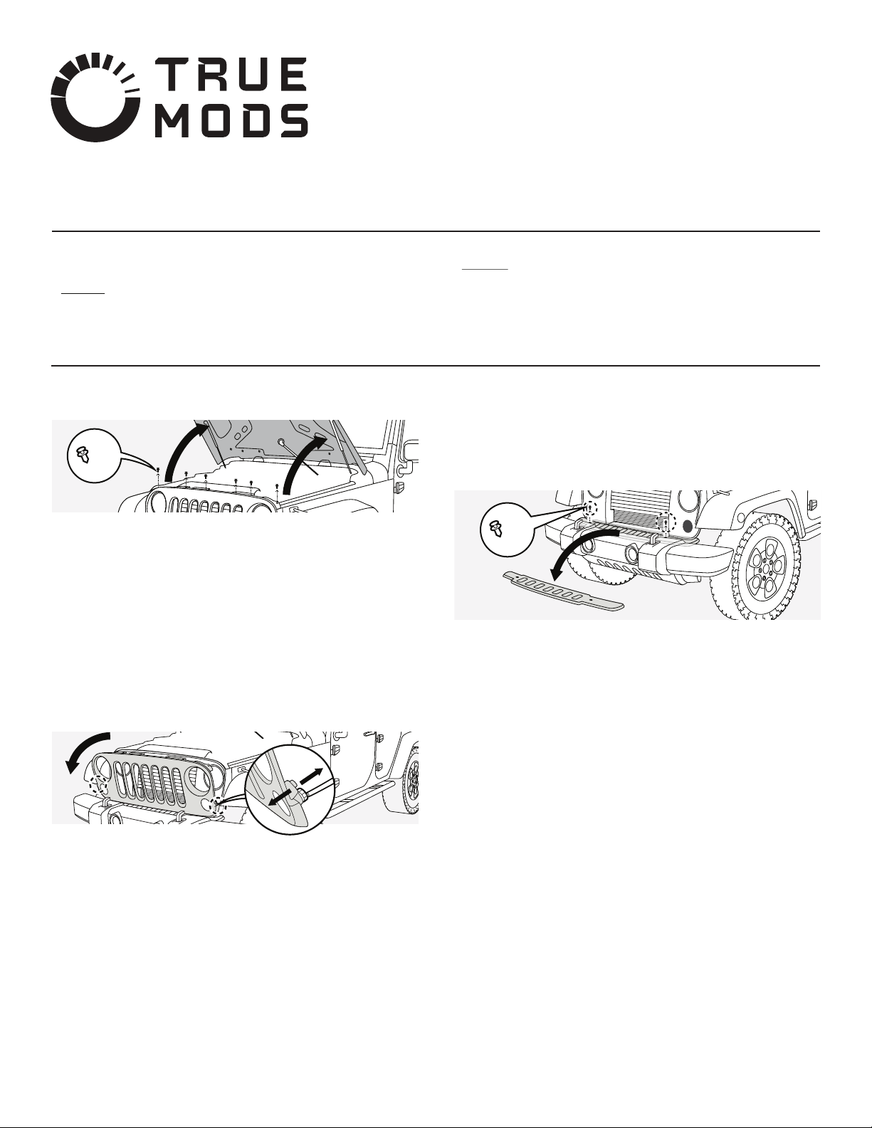
1.1 Open the hood.
1.2
1.3
Locate the six black plastic rivets along the top facing edge of the grille.
Remove all six rivets by using a at head screwdriver to pry up on and remove
the center section followed by the body of each rivet.
NOTE: If your vehicle comes with locking style connectors, carefully slide the red locking tab
toward the rear of the connector and then push the retaining tab to remove the connector.
1.6
1.7
Inspect for any other wires or lights attached to the grille and remove.
Remove grille from vehicle and place in a safe location.
1.4 Grab hold of the grille close to the base and pull it away from the vehicle with
a rm tug being careful not to pull the grille too far away from the vehicle as
the wiring for the turn/parking lights will still be attached at this point.
1.5 Tip the top edge of the grille away from the vehicle and carefully disconnect
the wiring harness from the back of the two factory turn/parking lights.
2.1
2.2
Locate the two black plastic rivets in the top of the bumper valance.
Remove both rivets by using a at head screwdriver to pry up on and remove
the center section followed by the body of each rivet.
NOTE: Your vehicle may have screw style rivets. If this is the case, the center section may be
removed with a Phillips screwdriver.
2.3 Grab the edge of the valance that is closest to the vehicle and carefully lift.
Once it clears the radiator supports it can be lifted away and removed.
Step 1: Remove the Grille Assembly
x6
x2
Step 2: Remove the Bumper Valance

True Mods © 2012-2021 All Rights Reserved
x6
3.1
3.2
Disconnect the vehicle harness from the back of the fog lights.
Locate and remove the four screws securing each fog light to the back side
of the bumper.
3.3 Remove the fog lights.
4.3
4.4
4.5
4.6
4.7
Take note of the location of the angle adjustment screw as you will need to
adjust this later when the lights are installed in the vehicle.
Attach each new fog light to the back side of the bumper using the four
screws removed from the original fog light.
Plug wiring harness adapter into each fog light.
Use zip ties to secure any hanging wires away from moving parts and pinch
points.
Using a screwdriver, turn the adjustment screw until the lights are correctly
adjusted.
Step 3: Remove the Fog Lights
5.1
5.2
5.3
5.4
5.5
5.6
5.7
5.8
5.9
Replace lower skid plate (air dam) if it was removed.
Replace bumper valance and its two plastic rivets by reversing the removal
procedure.
Position grille on top of the bumper in preparation for installation.
Plug wiring harness into parking lights making sure the red locking tabs are
pushed forward into the locked position.
Line the bottom of the grille up against the front of the vehicle making sure
the centering pin aligns with the centering hole while making sure that all of
the metal retaining clips line up with their respective holes.
Push rmly but carefully on the bottom of the grille so that all of the clips
seat in their holes.
Put all six plastic rivets back into the top of the grille.
Carefully inspect the work area for anything that may have been unplugged
on not reinstalled.
Close the hood and enjoy your new fog lights!
Input Voltage: 10 – 32 V DC
Input Current @ 12V DC:
Fog Light: 1.15A
DRL: 75mA (CAZLEDHDL1021, 1022, and 1032 only)
Turn Signal: 165 mA (CAZLEDHDL1021, 1022, and 1032 only)
Step 5: Replace All Removed Parts
Suggestions for Electrical Installation:
Splicing Location
Specications:
NOTE: The screws in the driver side fog lamp might be hard to reach with a regular Phillips
screwdriver. Consider using a stubby screwdriver instead.
TIP: A high quality dielectric grease may be used inside any electrical connector that may be
exposed to moisture in order to create a more weather resistant connection
TIP: At this point it is advisable to plug in and test the fog lights for correct operation before they
are installed in the vehicle.
TIP: At this point the fog lights can be removed. However, for better access and visibility while
working on the lights the lower plastic skid plate (air dam) may also be removed. To do so, locate the
six plastic rivets or screws holding the plate to the vehicle. There will be four across the front edge
and two at the back edge on the top side of the plate. Once these are removed the plate can be
dropped out and set aside.
Step 4: Install and Adjust New Fog Lights
4.1
4.2
Use the included blue and yellow extension wires to tap into the vehicles turn
signal and running light wiring (CAZLEDHDL1021, 1022, and 1032 only). For
suggestions on how to accomplish this refer to the Suggestions for Electrical
Installation section.
Plug the included adapter into the vehicle wiring harness.
•
•
•
•
•
•
•
•
The BLUE daytime running light (DRL) wire will need power supplied from a
ACC switched power source (power is on when the car is on but o when the
car is turned o). (CAZLEDHDL1021, 1022, and 1032 only)
The YELLOW turn signal wire will need power supplied from the power side
of the turn signal switch or a turn signal lamp. (CAZLEDHDL1021, 1022, and
1032 only)
The above requirements can often be met by tapping into the wiring of the
parking light harness behind the grille assembly. See step 1.5.
The parking light usually has a three-wire harness with one black wire and
two lighter colored wires. In most cases, the center wire in the harness is
switched power while the wire farthest from the black wire is power for the
turn signal.
Always use a multimeter to verify power is present on each wire only at the
appropriate times.
When power has been veried the correct wires can be spliced into the
factory harness using the method of your choice. Don’t forget, BLUE is DRL
and YELLOW is turn signals. (CAZLEDHDL1021, 1022, and 1032 only)
Since there are two fog lights and two parking lights, each fog light can be
wired into the closest parking light. This will reduce the amount of wire
needed and reduce the risk of wire damage.
Any exposed metal connectors should be protected with heat shrink tubing.
Wire Routing:
•
•
•
•
Always route wiring away from any moving parts and pinch points.
Never use more wire than necessary. Leave slack for movement but avoid
excess wiring. Not only does it look bad but it also increases the risk of
damage.
Never leave wires hanging. Use zip ties or other methods to secure wires to
a nonmoving part of the vehicle or an existing wiring harness.
Always consider using wire loom to protect wires from chang.
Other TRUE MODS Automobile Accessories manuals

Popular Automobile Accessories manuals by other brands

STROBES N MORE
STROBES N MORE Triple Threat Dual installation guide

Kolpin Outdoors
Kolpin Outdoors 25-8810 Assembly & owners manual

SkyLine
SkyLine Movo Evolution user manual

Whispbar
Whispbar K072W Fitting instructions

Axxess
Axxess AXDSPX-HN3 installation instructions

TOP VEHICLE TECH
TOP VEHICLE TECH KWPOR11 installation manual


