............ www.truemfg.com ............
True Food Service Equipment, Inc.
8 8
REMOTE UNITS (This section applies to remotes only!)
• Remote cabinets must be ordered as remote.
We do not recommend converting from a
standard self contained to remote system.
• All remote cabinets must be hard wired.
• No castors available.
• All remote cabinets come standard using 404A
refrigerant.
• All remote units come standard with expansion
valve, liquid line solenoid, heated condensate
pan, and defrost timer when applicable.
• Contact True Technical Service for BTU
requirements.
• No wiring necessary between cabinet and
condensing unit.
• All remote condensing units purchased from
True are 208/230 volts single phase.
If you have any questions regarding this section,
please call True at 1-(800)-325-6152.
INSTALLATION / OPERATION INSTRUCTIONS
SEALING CABINET TO FLOOR
Optional
A. It may be necessary to seal the deli case to the
floor for local sanitary codes or if the customer
so desires. TRUE recommends either of the
following methods.
B. Using a vinyl cover base trim as produced by
Armstrong, Johnson, or Kentile (available at floor
covering suppliers) or
C. Using mastics available at hardware stores.
D. When applying the cove base trim, thoroughly
clean both the cabinet and floor of dirt and
grease. Apply a recommended contact cement
to the cove base trim. After cove base trim has
dried, fill in cracks and joints with a caulking
material.
E. When applying a mastic, draw an outline of the
cabinet on the floor. Raise and block the front
side of the cabinet. Apply a bead of mastic to
the floor 1/2” inside the outline drawn. Lower
the cabinet. Raise and block the rear side of the
cabinet. Apply the bead of mastic, lower the
cabinet.
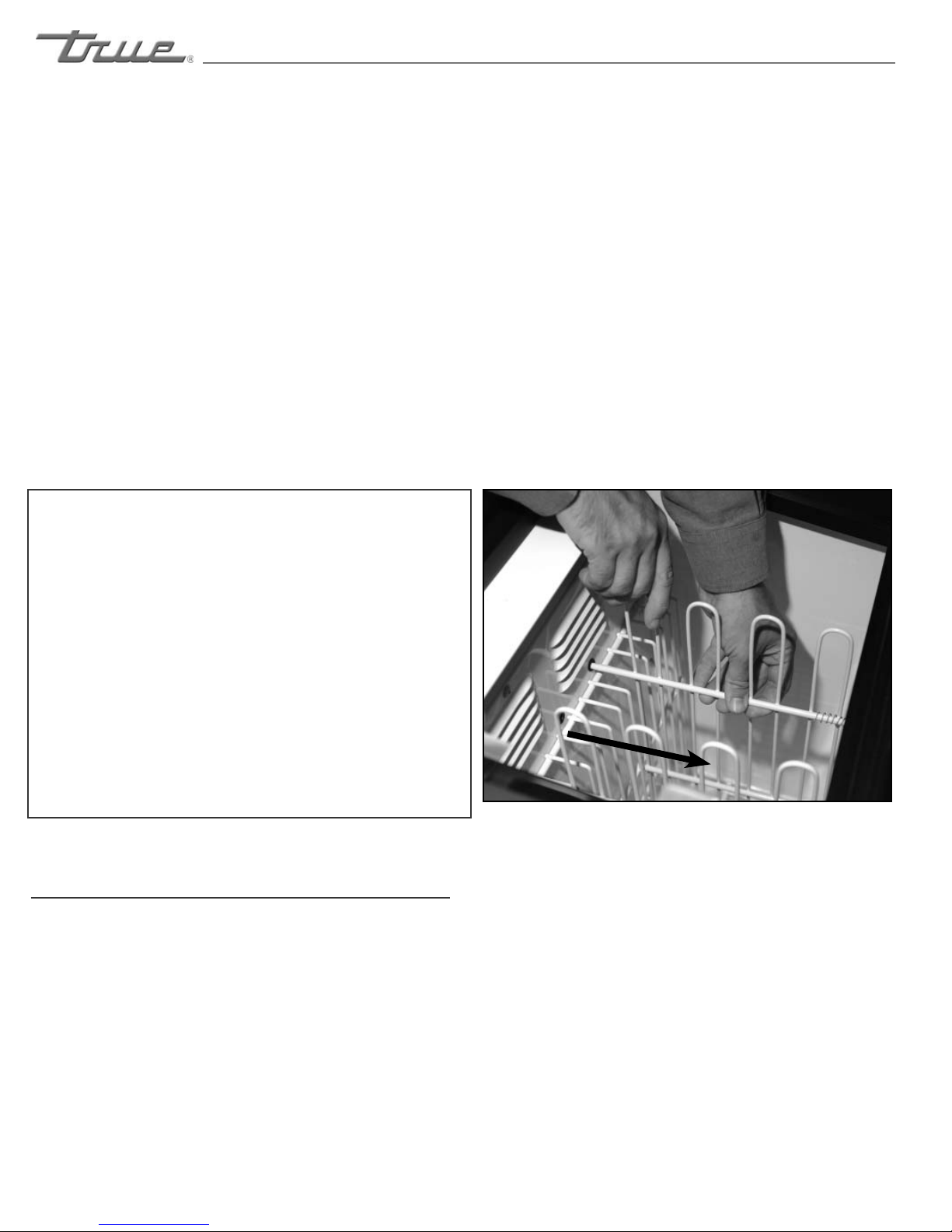
BIN DIVIDER INSTALLATION
STAINLESS STEEL
SHELF INSTALLATION
NOTE
Convenience merchandisers
are shipped with bin dividers
in place. If it is necessary to
adjust spacing the following
procedure is recommended.
Step 1
A. Dividers are spring loaded
- push divider towards front
of the cooler to release from
rear grommeted holes.
B. Lineup divider front pegs
with desired holes and punch
through interior tape lining
of both top and bottom holes
- bottom peg first (front holes
are taped over to improve
insulation values).
Remove divider from the
front holes and line up
regular and spring loaded
rear pegs with holes in line
with those desired in front.
Insert as far as possible and
maneuver front pegs in place.
Figure 1