TrueHVLP Apollo 7500 AtomiZer User manual

A
..
Apollo Sprayers
HVLP
Instruction Manual
7500
Series
••
•
•
tom
Apollo Sprayers
lnt'l.,
Inc.
1040
Joshua Way
Vista, CA
92081
760-727-8300
www.hvlp.com

1.
Safety
....................................................................................................................
3
2.
Introduction
.........................................................................................................
4
2.1 About Your New Spray
Gun............................................................................
4
2.2 The 7500 AtomiZer® & Turbine Systems
.......................................................
4
2.3 O.S. – Overspray Control/TexturingFeature
(Optional)
...............................
5
2.4 The 7500 AtomiZer®As A Bleeder Type Spray
Gun
.....................................
5
3.
Setup
........................................................................................................................
6
3.1 Installing Air Relief Mechanism (Turbine Systems
Only).............................
6
3.2 Installing And Using The O.S. (Overspray)
Control......................................
7
3.3 Cup Assemblies And Turbine Air
...................................................................
7
3.4 Installing A One Quart Cup Assembly (Turbine Air)
.....................................
9
3.5 Assembly Of Your Pressure Pot System
.....................................................
12
3.6 The 7500 AtomiZer® & Compressed Air
......................................................
13
3.7 Preparation Of 7500 AtomiZer For Production
Spraying
...........................
19
3.8 Installing Cup Air Regulator And Gauge (Compressor
Only)....................
20
3.9 Using Your 7500 AtomiZer With An Optional Handle Air
Regulator.
.........20
4.
Operation
.............................................................................................................
21
4.1 Spray Patterns
...............................................................................................
21
4.2 Spray Gun
Technique....................................................................................
22
4.3 Using The 7500 AtomiZer With A Turbine System
......................................
23
4.4 Using The 7500 AtomiZer With Compressed Air
........................................
23
4.5 Selecting Nozzles, Needles And Air Caps
...................................................
24
4.6 UnderstandingYour Viscosity Meter
...........................................................
25
4.7 Know Your Coating Properties
.....................................................................
25
4.8 Apollo HVLP Turbine
Properties...................................................................
26
4.9 Cleaning Your 7500 AtomiZer Spray
Gun
....................................................
26
5. Record Of Spray Gun Use
............................................................................
31
6. Record Of Spray Gun Maintenance
...........................................................
31
7.
Troubleshooting
...............................................................................................
32
8. Diagram & Parts List
.......................................................................................
33
9.
Warranty
.............................................................................................................
35
1. Safety
Read all instructions and safety precautions before operation.
Indicates a hazardous situation, which, if not avoided, will result in death or serious injury.
Indicates a hazardous situation, which, if not avoided, could result in death or serious injury.
Indicates a hazardous situation, which, if not avoided, could result in minor or moderate injury.
NOTIC
E
Indicates a situation that could result in damage to the equipment or other property.
• Risk of fire or explosion! Solvent and paint fumes can explode or ignite,
causing severe injury and property damage.
• Paints and solvents containing HALOGENATED HYDROCARBONS can react
explosively with aluminum. Always check the product’s label before using
these materials in the unit.
• Hazardous vapors: Paint, solvents, insecticides and other materials may be
harmful if inhaled, causing severe nausea, fainting or poisoning.
• Make sure the room is well ventilated. Avoid all ignition sources, such as
static electricity, sparks, open flames, hot objects, sparks from connecting
and disconnecting power cords, and working light switches.
• Follow the material and solvent manufacturers’ safety precautions and
warnings. Do not use liquids with flash points less than 100° F (38° C).
• Static electricity can be produced by HVLP spraying. Make sure any
electrically conductive object being sprayed is grounded to prevent static
sparking. The sprayer is grounded through the electrical cord to prevent
static sparking.
• Use a respirator or mask whenever there is a chance that vapors may be
inhaled. Read all instructions with the mask to ensure that the mask will
provide the necessary protection against the inhalation of harmful vapors.
NOTIC
E
Tipping the spray gun causes the spray gun to clog. Dried spray material also clogs the pressure
delivery tube and fittings. The spray gun does not function when clogging occurs.

2. Introduction
You are about to experience a unique, superb performing
TrueHVLP™ spray gun. The Apollo 7500 AtomiZer® offers
the most modern and advanced HVLP technology available
today. Special features are our new Xpansive™ Fan Control,
and MicroTech™ Atomization Technology. Please take a few
minutes to read about these features so that you can
experience the ease and benefits of TrueHVLP™ spray
finishing. The Apollo 7500 AtomiZer® spray gun comes pre-
tested and packaged in a custom spray gun case for proper
storage and protection.
You should have the following items in the case:
• A 7500 AtomiZer® spray gun with 1.0mm nozzle and
needle paired with a “B”Air Cap (Gold) installed.
• Wrench (Spanner)
• Cleaning Brush
• Air Feed Connector (#22)
• Non-return valve
• 1 x 1 quart (1 liter) cup top gasket OR 1 x 250cc/600cc/1000cc (dependent on the cup size) cup top gasket OR 1 x 8
ounce cup top gasket
• Sample bottle – spray gun lube
• Instruction manual
2.1 About Your New Spray Gun
The Apollo 7500 AtomiZer HVLP spray gun is a multi-use, multi-purpose HVLP spray gun. The 7500 AtomiZer will operate
on most professional HVLP turbine systems or as a TrueHVLP™ spray gun on any air compressor (3hp – 20 gal [75 liter]
tank or larger). The 7500 AtomiZer is designed to operate as a production spray gun from a fluid feed system, a bottom
mounted cup gun or as a top mounted cup gun.
2.2 The 7500 AtomiZer® & Turbine Systems
The 7500AtomiZer is a standard turbine spray gun – non-bleed type. When the turbine is turned on, NO air will flow through
the spray gun. When the trigger is partially pulled, air will flow through the air cap. When the trigger is fully pulled, paint will
flow through the nozzle (tip) to meet the air flow, atomize and project to your work surface. It is most important that your
turbine system be equipped with a proper internal air relief valve to
handle the back pressure when the trigger is released and the turbine
is running.
All Apollo models manufactured after 2007 which includes; 725, 825, 835,
835VR, 1025, 1035, 1040VR, 1050, 1050VR, Power-3, Power-4, Power-5,
Precision-5 and Precision-6 are equipped with an internal air relief valve. All
otherApollo models manufactured prior to 2007 and not previously listed will
require an external relief valve that must be attached to the air outlet on the
turbine before using the 7500 Atomizer spray gun. Failure to install part
number A7538A when using the 7500 AtomiZer spray gun with older turbine
systems can cause premature failure of the turbine motor due to excessive
back pressure and will void your warranty.
If you are using the Apollo 7500 AtomiZer spray gun with a turbine system other than one manufactured by APOLLO, it is
advised to inquire with the turbine manufacturer to determine if your unit is configured to accept a non-bleed spray gun. If
you are not sure, or if you cannot get accurate information it is strongly advised that you install Apollo part number A7538
prior to using the 7500AtomiZer spray gun.

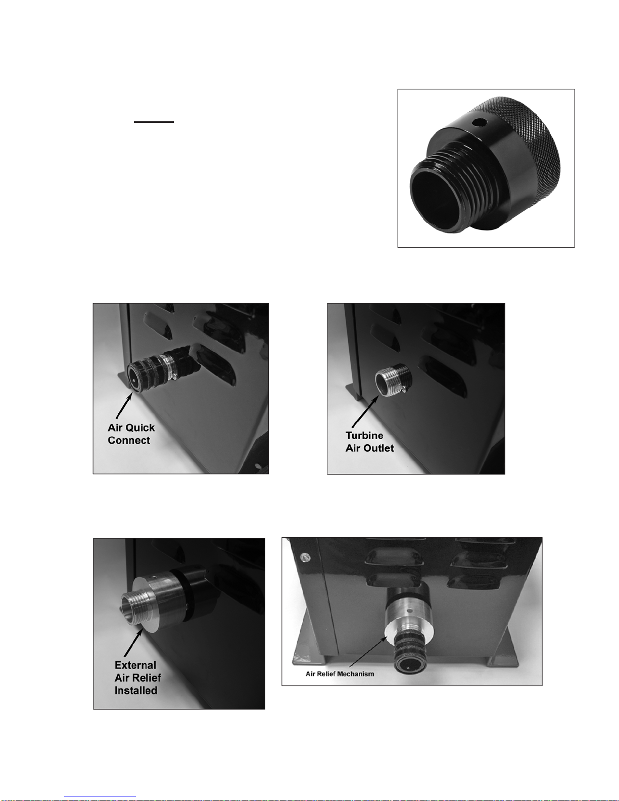
2.3 O.S. – Overspray Control/TexturingFeature (Optional)
The O.S. control will permit the safe reduction of air flow and air pressure fromthe turbine, when necessary. The O.S. control
should be used if an extremely thin coating or low viscosity product is being sprayed and you desire to reduce atomizing
pressure to achieve maximum efficiency and the least amount of overspray for your turbine unit. The O.S. control can also
be used to create a textured or splatter effect with selected coatings.
NOTE: O.S. Control is not needed when using an 835VR, 1050VR or Precision 5 variable speed
turbine system.
2.4 The 7500 AtomiZer®As A Bleeder Type Spray Gun
With the appropriate optional adapter, the 7500 AtomiZer can be operated as a bleeder type spray gun. Note there is a
blanking cap (#12B page 33) above the material adjusting screw (#19, page 33), this is where the upper port air hose coupler
(#12C, page 33) fits. Make sure you also blank the bottom of the handle with part (#28, page 33). This arrangement will
bypass the non-bleeder valve assembly and allow you to operate your 7500T spray gun as a “bleeder” style gun.
Sometimes it’s not convenient to have the hose connected to the bottom of the handle. This option also allows you to hold
the hose in a different position, by connecting your air hose to the top of the spray head and running the hose over your
shoulder. This is especially nice when spraying, hoods on cars, tables, or inside bathtubs.
3. Setup
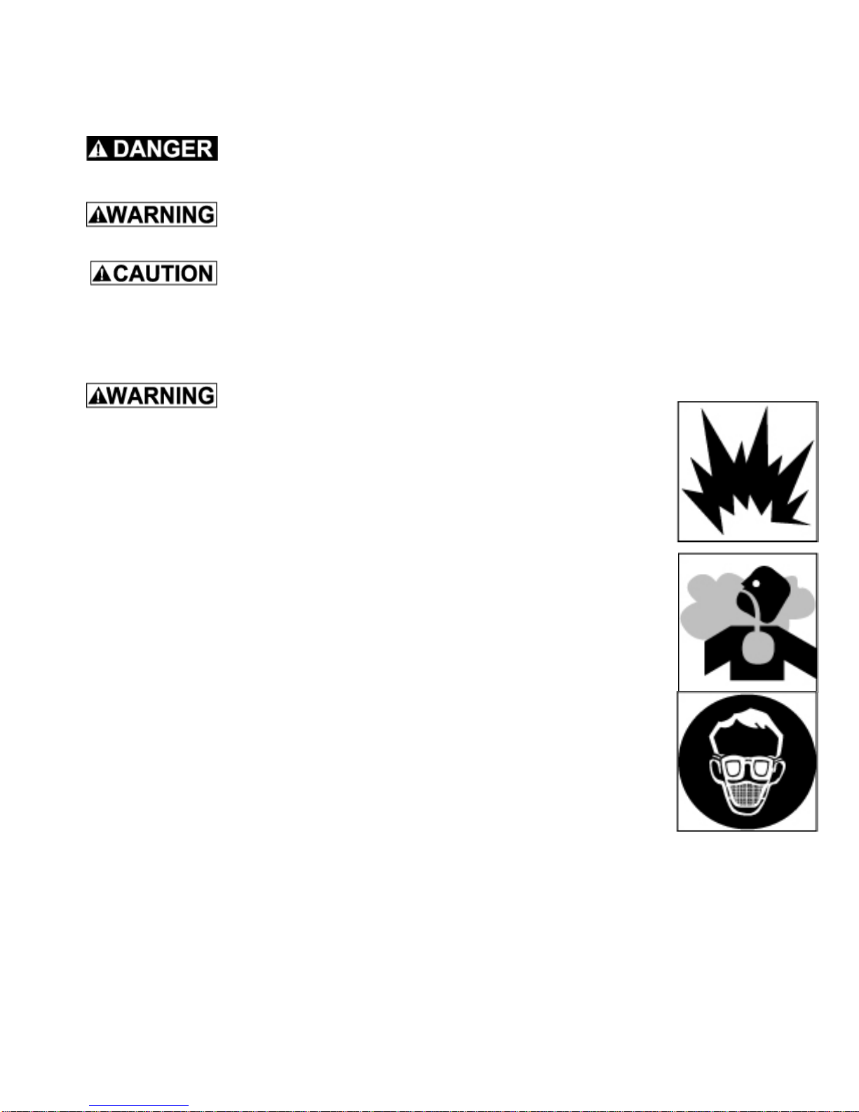
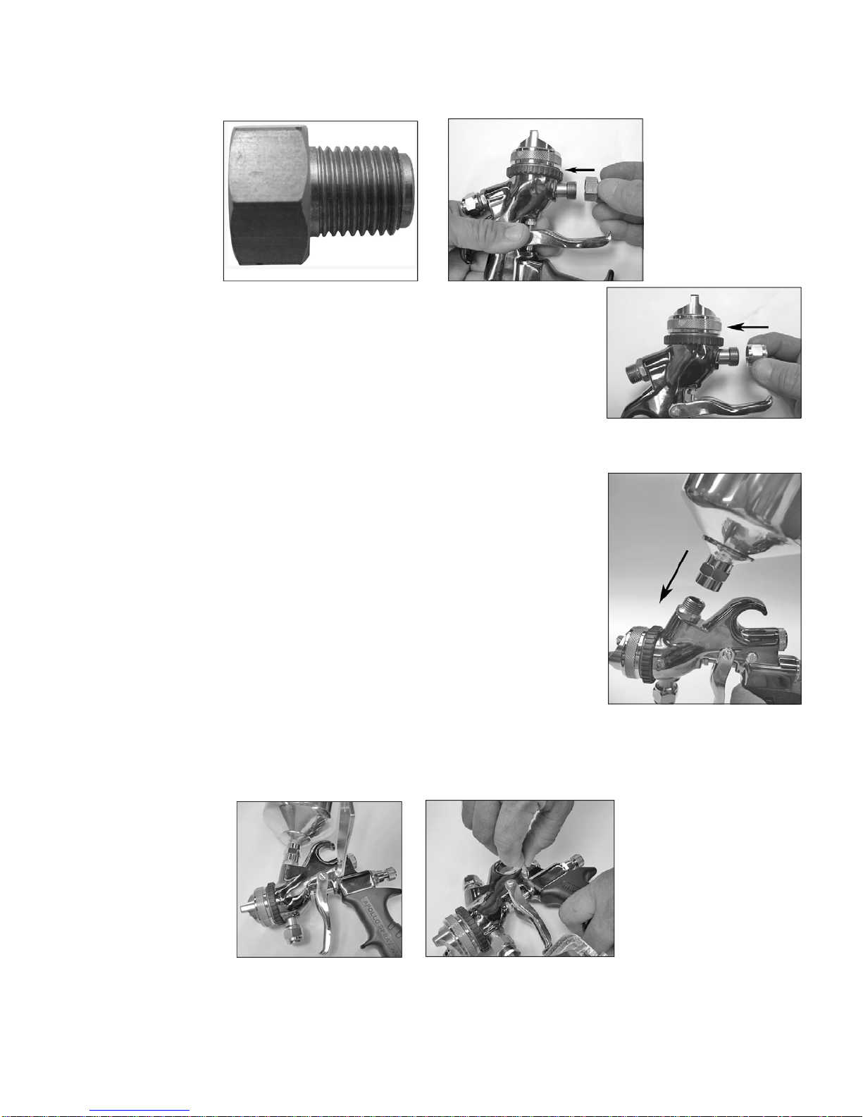
3.1 Installing Air Relief Mechanism (Turbine Systems Only)
As previously noted,Apollo Models 725, 825, 835, 835VR, 1025, 1035, 1040VR,
1050, 1050VR, Power Series and Precision Series have an air relief mechanism
internally installed and DO NOT require an external air relief mechanism. All
other Apollo Models require theinstallation ofApollo Part #A7538A to the turbine
air outlet prior to operating The AtomiZer 7500 spray gun.
The air relief mechanism Part #A7538A must also be installed on ANY MAKE
turbine system that does not have an air relief mechanism installed. If using with
a system other than Apollo, please check with the manufacturer to determine if
a non-bleed spray gun can be safely operated on your system. If not, install Part
#A7538A before operating the 7500AtomiZer spray gun.
A7538
To install Part #A7538AAir Relief Mechanism, first locate and remove theAir Hose Quick Connect.
Second, screw the air relief mechanism onto the turbine air outlet. Third, screw the Air Hose Quick Connect onto the Air
Relief Mechanism. Make sure to install theAir Relief Mechanism with the bleed hole pointing upwards. Failure to do so, will
blow dust and dirt around on the floor while you are spraying.
3.2 Installing And Using The O.S. (Overspray) Control
To install the optional O.S. control follow these steps:
1. Remove the Upper Port Cap (12B, Page 33) and screw O.S. control
in its place.
2. Rotate the O.S. control air flow screw counterclockwise (anti-
clockwise) to its full open position. It is now ready to use.
Keep the O.S. control in the full open position when not in use. Rotate
the O.S. Control air flow screw counterclockwise (anti-clockwise) until it
stops, this is its full open position.
To operate, turn the air flow control screw clockwise at least 2/3 of the way
in. Test spray to see if the reduced flow of air reduces overspray/pressure
to your desire. If not, continue to rotate the air flow control screw until the
desired results are achieved. Be sure that you still have enough pressure
to atomize your coating to provide a good quality finish. If not, increase the
air flow by turning the screw counterclockwise until you feel you have the
most efficient results.
To create a textured or splattered paint effect, turn the air control screw all the way closed (clockwise). Do not thin your
paint, or if you have to, thin it very slightly to permit it to flow. Hold the spray gun further back from the work piece than you
normally would for regular finish spraying, at least 8” or more. You should now have a splatter effect. Adjust paint viscosity
accordingly to produce desired particle size.
In order to properly protect your turbine, you cannot completely shut off the air flow with the OS Control.
If you still feel that you are experiencing overspray, please refer to your instruction manual or to our website FAQ pages for
additional information.
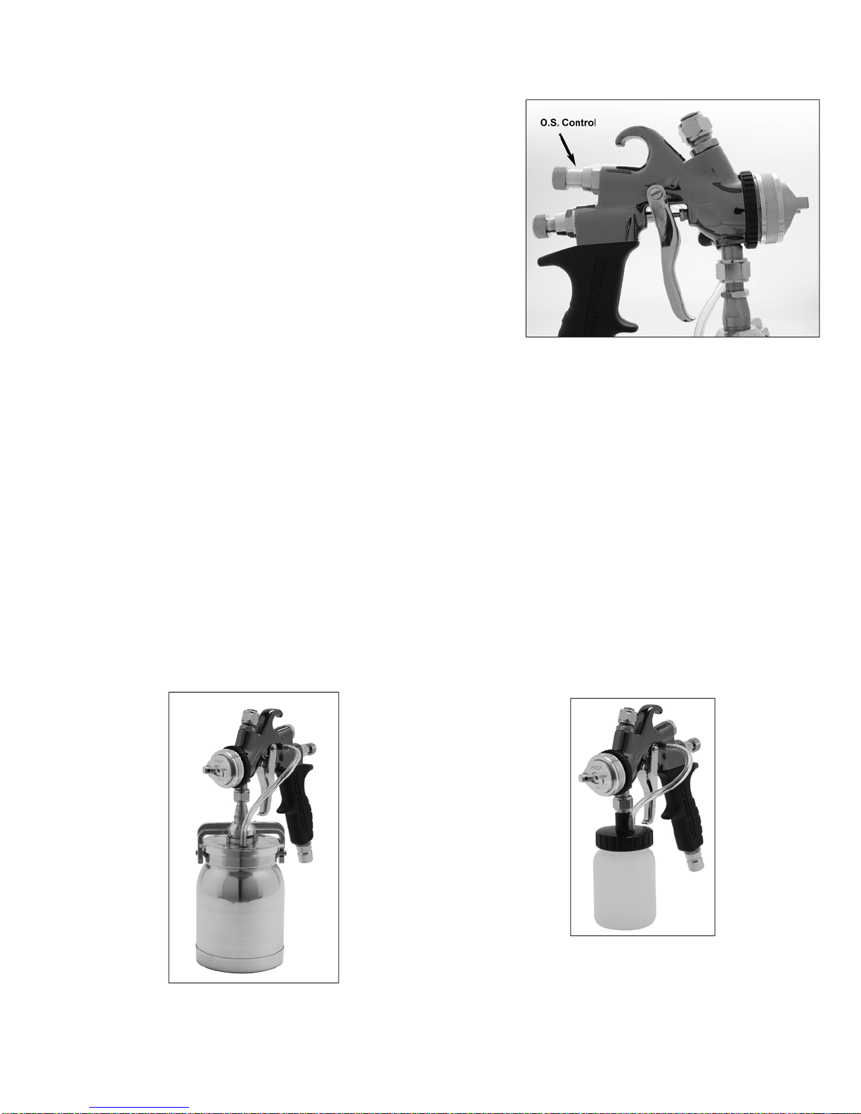
3.3 Cup Assemblies and Turbine Air
A variety of cup assemblies are available for the 7500AtomiZer.
You can install a standard 1 quart (1 liter) cup
assembly to the 7500AtomiZer spray gun. An 8oz. (250cc) mini-cup assembly can be installed on
the 7500 AtomiZer spray gun when smaller quantities
of material are to be sprayed or when a smaller cup
assembly is desired.

A3oz (88cc) super-mini cup assembly can be installed on the 7500 for even smaller quantities of material or for compliance
with local regulations.
A top mounted gravity cup can also be used. Apollo offers a 250cc, 600cc and 1000cc top mounted cup.
250cc Cup 600cc Cup 1000cc Cup
The 7500AtomiZer can also be used as a production spray gun in conjunction with any size pressure pot.Apollo offers a 2
quart (2 liter), a 2.5 gallon (10 liter), and 10 gallon (37 liter) pressure pot (not shown).
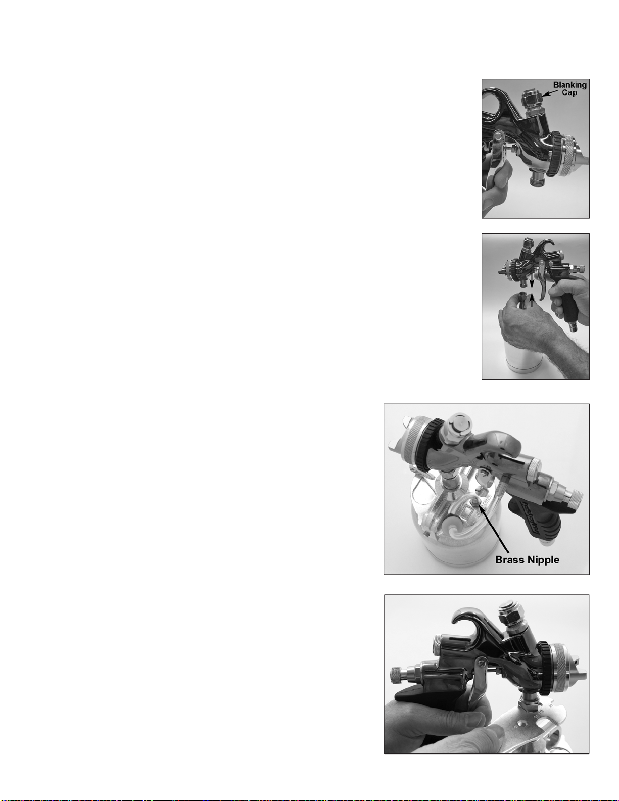
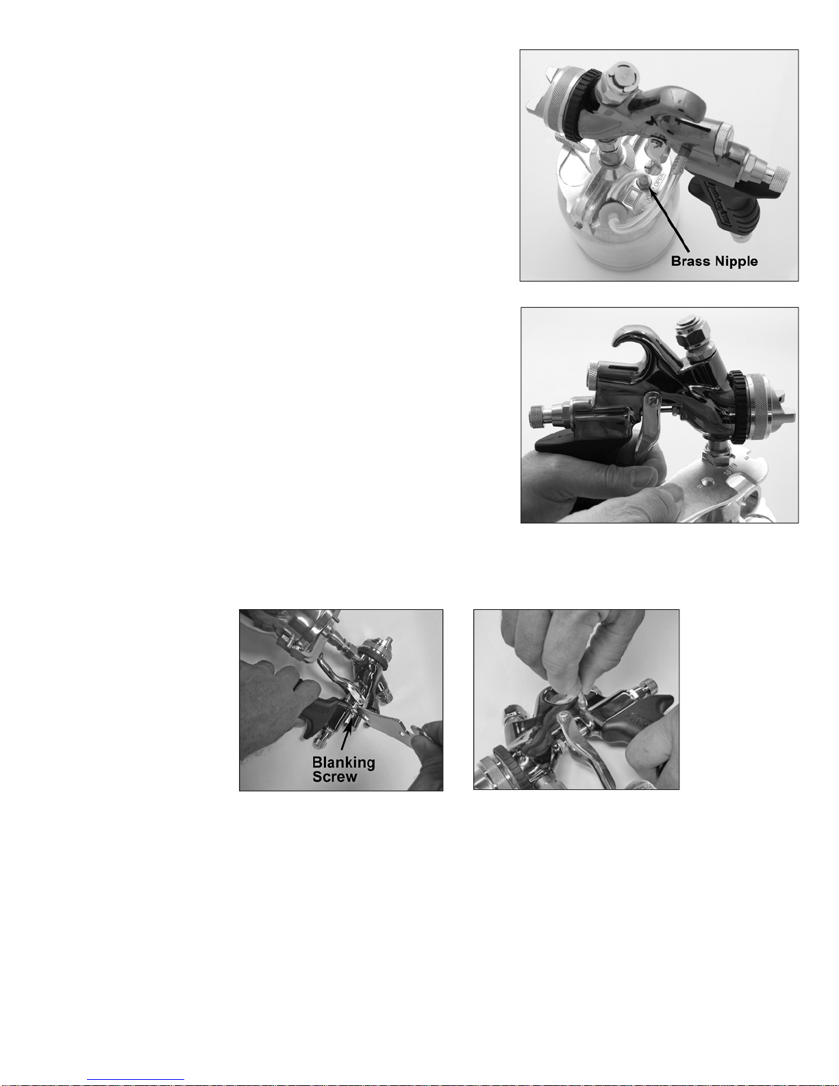
3.4 Installing A One Quart Cup Assembly (For Use With Turbine Air)
To install a standard 1 quart (1 liter) cup assembly to the 7500 AtomiZer turbine spray gun follow these simple instructions:
1. Locate the cap (#11, page 33) that blanks the material connector not being used and make
sure that it is installed on the top material connection (#30, page 33).
2. Screw the cups center bolt to the material connector (#29, page 33), finger tight.
3. Locate the brass air feed nipple on the cup top and rotate the cup lid so
that the brass nipple is in the 7 o’clock position and the cup lever is in
the front of the gun.
4. While holding the cup assembly firmly, tighten the cups center bolt with
the wrench (spanner) supplied.

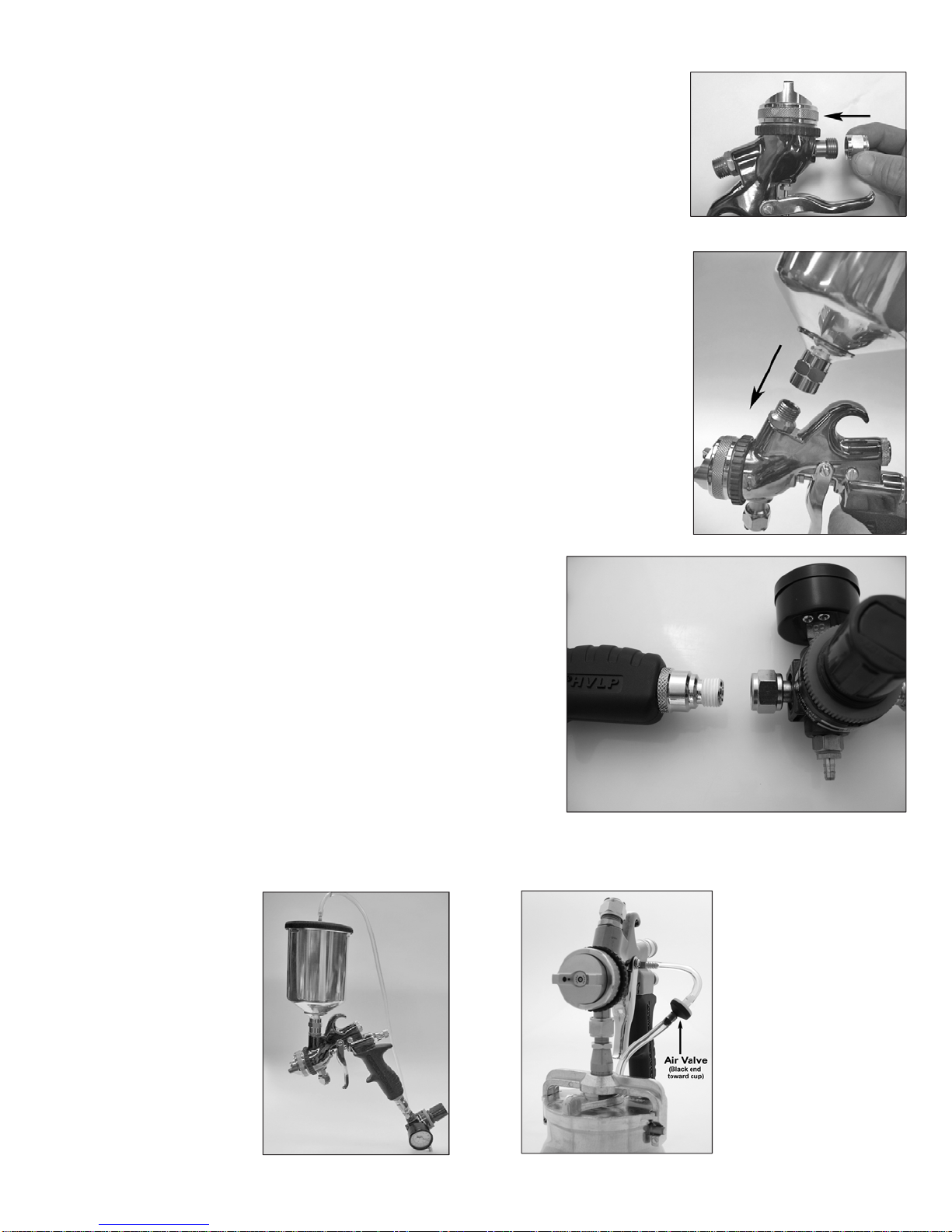
5. Remove the stainless steel screw located on the side of the spray gun and replace it with the air feed connector (#22,
page 33) located in the plastic bag inside your spray gun box.
6. Join the air hose to the spray gun from the cup. Connect one end of the air hose to the air feed connector (#22, page
33), and the other end to the brass nipple in the top of the cup lid. Be sure that the black half of the valve is facing toward
the cup.
3.4.1 Installing A Mini Cup Assembly
An 8oz. (250cc) or 3oz. (88cc) cup assembly can also be installed on the material connector when smaller quantities of
material are to be sprayed or when a smaller cup assembly is desired.
To install the 8oz. (250cc) or 3oz. (88cc) cup assembly, first install the material adapter,A4150. Locate the material connector
(#29, page 33) and screw the material adapter on. Follow the installation instructions for the 1 quart (1 liter) cup assembly.
3.4.2 InstallingA Gravity Fed Cup Assembly (Turbine Air Only).
1. Locate the cap (#11, page 33) that blanks the unused material connection and make
sure that it is installed onto the bottom material connection (#29, page 33).
2. Screw the top feed cup to the top material connection (#30, page 33) and tighten with
the wrench (spanner). You are now ready to spray.
3. Sometimes when spraying heavy materials cup pressure is required. If cup pressure is required, remove the stainless
steel screw located in the side of the spray gun and replace it with the brass air feed connector (#22, page 33). This is
where your air hose joins the spray gun from the cup.

4. Connect one end of the air hose to the air feed connector (#22, page 33) and the other end to the brass nipple in the
top of the cup lid. Be sure that the black half of the valve is facing toward the cup.
3.5 Assembly Of Your Pressure Pot System
There are many advantages to using pressure pots with a turbine system.Apollo Sprayers have made this very easy with
our fluid feed systems, 4500 and 4550. By removing the paint cup from the spray gun you immediately reduce the overall
weight of the spray gun by approximately 50%. You also get a smaller tool to hold in your hand thereby allowing you to more
easily access the back of cabinets or other tight spaces where a standard cup gun would not fit. By using a pressure pot you
are able to spray larger quantities of material without stopping to refill a smaller cup. This can save a lot of time on a long
job where you are spraying the same material all the time.
Using a pressure pot with any size turbine system is very easy.All you need is any size pressure pot, a fluid hose and a small
air compressor. When using a remote cup or pressure pot, it is necessary to introduce compressed air in order to pressurize
the remote pot and move the fluid from the pot to the spray gun tip/nozzle. In general 5PSI (0.345 Bar) of air pressure
is adequate to push most average viscosity fluids to the spray gun nozzle. Higher pressure would only be necessary for
heavier viscosity fluids or if you are spraying up a ladder where the fluid has to travel more than 6 feet in elevation. To set
up your 7500AtomiZer for use with a pressure pot, follow these instructions:
1. Connect the black fluid hose to the fluid outlet on the top of the pressure pot. Refer to your pressure pot instructions for
the specific location of the fluid outlet.
2. Seal the threads with Teflon tape and tighten with a wrench (spanner) to assure no fluid leaks once you pressurize the
pot.
3. Connect the air line from your compressor to the air inlet on the pressure pot. This should be a male quick connect
adjacent to the regulator and gauge. If your quick connect is the same style as the one on the pot you can pull back the
ring on the female end and insert into the male end, releasing the ring to fasten them together.
4. Connect the other end of the black fluid line to the material connector on the spray gun. (#29, page 33).
NOTE: Make sure that the top material connector (#30, page 33) has been capped with the material blanking cap (#11,
page 33).
NOTIC
E
Do not attempt to remove part# 29 or 30, page 33. Spray gun may leak internally.
5. Connect your turbine air hose as normal.
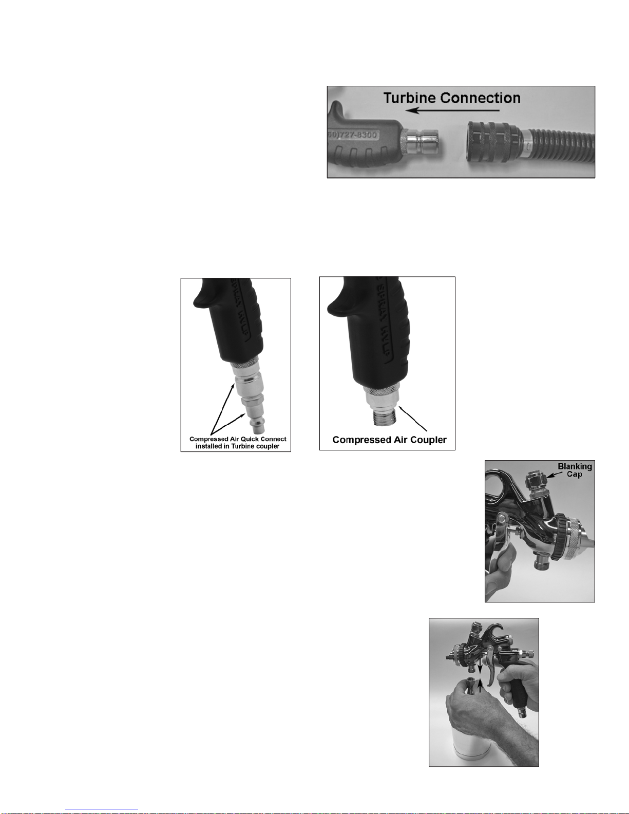
3.6 The 7500 AtomiZer® & Compressed Air
The 7500AtomiZer spray gun can easily become aTrueHVLP™ compressed air spray gun (conversion gun) by unscrewing
the male Turbine quick connect coupler (#27, page 33) and replacing it with the compressed air handle coupler (#37, page
33) or screwing a standard male compressed air fitting directly into the turbine handle coupler.
3.6.1 Installing A Cup Assembly (Compressed Air)
To install a standard 1 quart (1 liter) cup assembly to the spray gun follow these simple instructions:
1. Locate the cap (#11, page 33) that blanks the material connector not being used and make
sure that it is installed on the top material connection (#30, page 33).
2. Screw the cups center bolt to the material connector (#30, page 33), finger tight.
3. Locate the brass air feed nipple on the cup top and rotate the cup lid
so that the brass nipple is in the 7 o’clock position.
4. While holding the cup assembly firmly, tighten the cups center bolt with
the wrench (spanner) supplied.
5. Remove the stainless steel screw located in the side of the spray gun and replace it with the brass air feed connector
(#22, page 33).
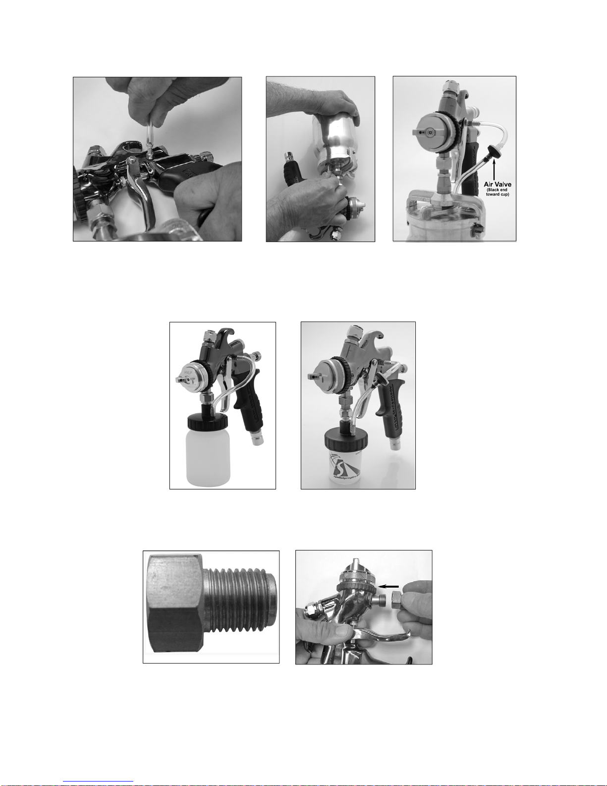
6. Join the air hose to the spray gun from the cup. Connect one end of the air hose to the air feed connector (#22, page
33), and the other end to the brass nipple in the top of the cup lid. Be sure that the black half of the valve is facing toward
the cup.
3.6.2 Installing A Mini Cup Assembly (Compressed Air)
An 8oz. (250cc) or 3oz. (88cc) cup assembly can also be installed on the material connector when smaller quantities of
material are to be sprayed or when a smaller cup assembly is desired.
1. To install the 8oz. (250cc) or 3oz. (88cc) cup assembly first install the material adapter, A4150. Locate the material
connector (#29, page 33) and screw the material adapter on, make sure you seal the threads with Teflon tape or other
thread sealer. Follow the installation instructions for the 1 quart (1 liter) cup assembly.
3.6.3 Installing a Gravity Fed Cup Assembly (Compressed Air Only)
1. Locate the cap (#11, page 33) that blanks the unused material connection and make
sure that it is installed onto the bottom material connection (#29, page 33).
2. Screw the top feed cup to the top material connection (#30, page 33). You are now
ready to spray.
3. Sometimes when spraying heavy materials cup pressure is
required. Attach the cup air pressure regulator to the bottom of the
spray gun handle.
4. Connect one end of the air hose to the cup air pressure regulator.
5. Connect the other end of the air hose to the brass nipple in the top of the cup lid. Be sure that the black half of the valve
is facing toward the cup.

3.6.4 Using Your 7500 AtomiZer With A Pressure Pot
Using a pressure pot with your 7500 AtomiZer spray gun is very easy. All you need is any size pressure pot, a fluid hose,
a 3/8” diameter air hose and any air compressor 3hp with a 20 gal (75 liter) air tank or larger. We recommend a pressure pot
with two regulators. One to regulate air pressure to the spray gun and a second to regulate air pressure to the pressure pot.
The basic 7500CAtomiZer spray gun is ready to set up for production use with your pressure pot.
If you are converting your 7500 AtomiZer from a cup gun to production, follow these steps first. If not, skip to step one of
Section 3.7 for preparation:
1. Disconnect the air feed tube from the side of the spray gun.
2. Remove the air feed connector (#22, page 33) and reinstall the blanking screw.
3. If you were using a gravity cup, move the blanking cap from the bottom connector to the top.
NOTE: Make sure that the top material connector (#30, page 33) has been capped with the
material blanking cap (#11, page 33).
NOTIC
E
Do not attempt to remove part# 29 or 30, page 33. Spray gun may leak
internally.

3.7 Preparation Of 7500 AtomiZer For Production Spraying
1. Apply a thread sealer or Teflon tape around the threads of the fluid connector (#29, page 33) on the spray gun.
2. Connect fluid hose to the fluid connector on the spray gun. Tighten firmly with a wrench (spanner).
3. Connect 3/8” air hose to handle coupler (#37, page 33) of the 7500 AtomiZer spray gun using a quick connect coupler.
4. Connect the fluid hose to the fluid outlet on the top of the pressure pot. Refer to your pressure pot instructions for the
specific location of the fluid outlet. Seal the threads with thread sealer or Teflon tape and tighten with a wrench (spanner)
to assure no fluid leaks once you pressurize the pot.
2.5 gallon (10 litre) deluxe pressure pot. 2 quart (2 litre) pressure
pot.
5. Connect the 3/8” air line to the regulator air outlet on the pressure pot.
6. Connect the air line from your compressor to the air inlet on the pressure pot. This should be a male quick connect
adjacent to the regulator and gauge. If your quick connect is the same style as the one on the pot you can pull back the
ring on the female end and insert into the male end, releasing the ring to fasten them together.
It is necessary to testthe air pressure in the pressure pot tomake sure that it is appropriate for the viscosity of material being
sprayed and the situation in which it is being sprayed.You don’t want the material coming out too quickly so that you get runs
and sags, but you also don’t want it to come out too slowly so that you are spraying very slowly. To test the air pressure in
the pressure pot follow these simple instructions:
1. DO NOT turn on the regulator to the spray gun.
2. Make sure your air hose and material hose are connected appropriately to the pressure pot.
3. Turn on your air compressor and wait until you have about 5PSI (0.345 Bar) in the pressure pot. Then, pull the trigger
on the spray gun until a stream of fluid flows from the tip/nozzle. NOTE: This may take a few minutes depending on the
length of your fluid hose.
4. Adjust the pressure on the pot regulator until the fluid drops off or bends at approximately 2-1/2 “ (6.35cm).
5. Your pot air pressure should be correct at this point, however, if the stream bends too short then increase the air
pressure. If the stream bends too far, then reduce the air pressure. If you need additional help, please feel free to call
our technicians at 1-888-900-4857.
Depressurize pressure pot using safety valve when equipment will be idle for a while.
This will prevent excess fluid from remaining in fluid hose, and prevent a possible accident
if the trigger is pulled causing material to stream from the spray gun.
Always ensure that the remote pot is tightly sealed, and all gaskets are in good shape, to prevent air and fluid leaks. Be sure
to flush and clean the fluid hose at the end of a work session. For smaller jobs, insert a one gallon can inside a 2.5 gallon
(10 litre) pressure pot. This will help to keep the inside of the pot cleaner and reduce the time necessary for cleaning up
when you are finished.

3.8 Installing Cup Air RegulatorAnd Gauge (Compressor Only)
(Optional item)—Recommended when using gravity cup with pressure. When using The 7500AtomiZer® with compressed
air and a pressurized gravity cup, it is necessary to regulate the pressure to the cup to ensure proper delivery of material
to the spray nozzle (approximately 3psi – 5psi). Failure to install the air regulator can result in leakage around the cup
seal, and/or poor finish quality. No regulator is necessary when using The 7500 AtomiZer as a production spray gun from a
pressure pot system or other styles of cup assemblies.
1. Install the compressed air handle coupler onto the bottom of the handle (#37, page
33).
2. Thread the regulator onto the handle coupler so that the gauge is located to the right of
the spray gun.
3. Once your gravity cup of choice is installed connect the air feed tube from the brass nipple on the regulator to the brass
nipple on the cup lid.
4. Be sure that the black half of the valve is facing toward the cup.
3.9 Using Your 7500 AtomiZer With An Optional Handle Air Regulator.
Your 7500 AtomiZer spray gun can be used with a regulator attached at the bottom of the handle. This will allow you to
adjust your air pressure from the spray gun, rather than your wall regulator or compressor.
To install the handle air regulator follow these instructions:
1. Locate the compressed air handle coupler (#37, page 33).
2. Attach regulator as shown in picture.
3. Attach quick connect coupler to regulator.
4. Attach air hose to quick connect coupler and adjust air pressure as needed.
4. Operation
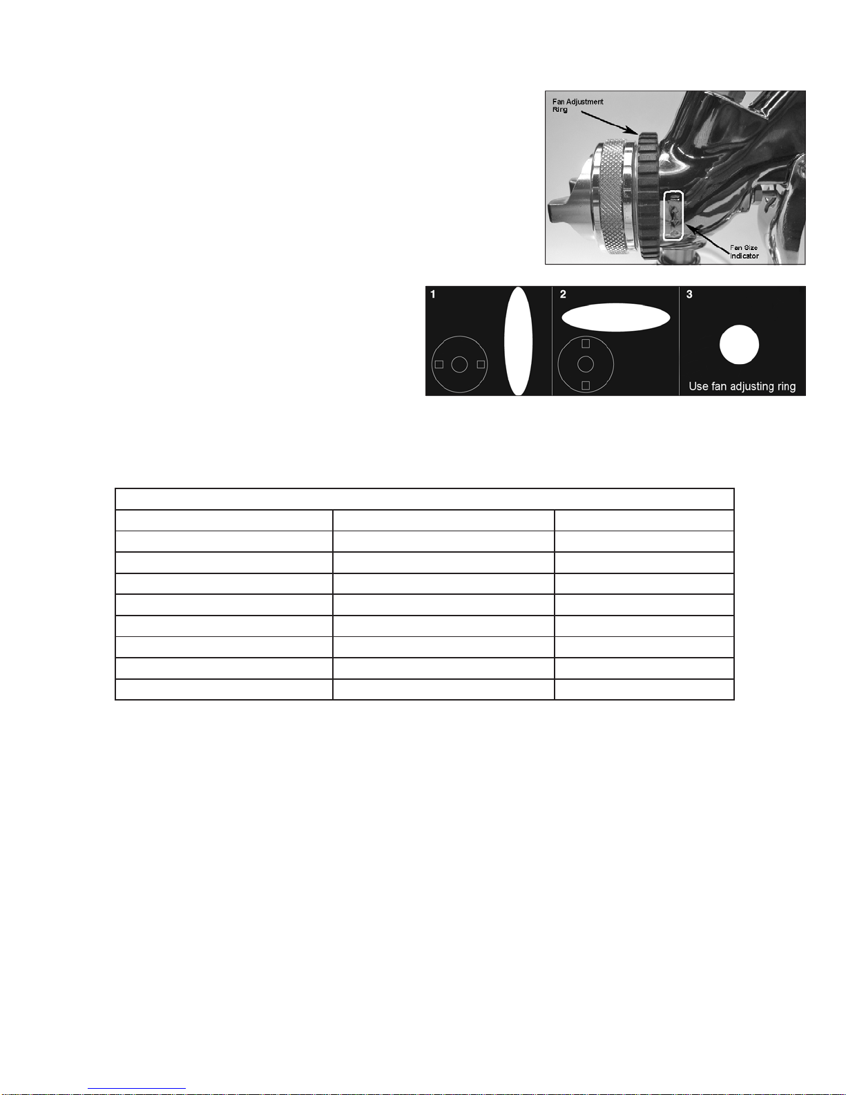
TheApollo 7500AtomiZer has a unique and simple fan pattern control. Locate
the Fan Adjustment Ring. Turn the spray gun on its side and notice the fan
size indicator stamped into the spray head casting, just to the right of the fan
adjustment ring. You will notice that there is a “-” sign at the top and a “+” sign
at the bottom with two arrows indicating the direction of rotation. Rotating the
ring UPWARD will begin to reduce the size of the fan pattern until the pattern
is round. Rotating the ring DOWNWARD will provide a full, open, wide pattern.
(Relative to the distance the spray gun is held from the work surface). To adjust
the direction of the fan pattern, loosen the air cap ring, (#1, page 33) rotate the
air cap ears (#2, page 33) to either a vertical or horizontal position as noted in
the diagram. This will provide your vertical or horizontal fan pattern.
4.1 Spray Patterns
Fig. 1 Use this position when spraying across from side
to side.
Fig. 2 Use this position when spraying from top to bottom.
Fig. 3 Use this position for spotting small objects, corners
and sharp angles.
Install the appropriate fluid nozzle, needle assembly and color coded air cap (A, B, C or D) for the viscosity of the fluid being
sprayed. See chart for recommendations (Section 4.5). Your spray gun is supplied with a 1.0mm Fluid Nozzle and Needle
Assembly paired with a “B” (Gold) air cap. Prepare coating. (Thinning if necessary). Filter and pour into spraygun. See chart.
Viscosity Chart
Guideline
Coating Thin/Reduce Viscosity in Seconds
Lacquers 25% - 50% 15-22 seconds
Sanding Sealer 20% - 30% 15-22 seconds
Enamels 20% - 40% 16-22 seconds
Stains use from can 15 seconds
Acrylic Enamel 50% - 60% 15-17 seconds
Catalyzed Polyurethane 10% - 30% 15-18 seconds
Varnishes 20% - 30% 16-22 seconds
Waterbase Coatings 00% - 10% 24-34 seconds
Viscosity chart should be used as a guide to thinning various coatings. Actual reduction will depend upon model turbine
used, flow out properties of the coating and the final visual results of the sprayed work piece. Seconds quoted are measured
in a Zahn #2 Viscosity Cup.
Table of contents


