Binks Mag II User manual

Mag II autoMatIc
aIR-assIsted
aIRLess HVLP sPRay gun
(u.V. and conVentIonaL coatIngs)
0511-0HF0, 0511-0Ht0, 0511-MHF0, 0511-MHt0
The following instructions provide the necessary
information for the proper operation and
preventive maintenance of the Binks MAG II
Automatic Manifold Mounted Air-Assisted
Airless HVLP Spray Gun. Please read and
understand all information in this document in
order to get the maximum performance from
your new MAG II spray gun.
In the MAG II Automatic HVLP spray gun, the
paint or other material to be sprayed is atomized;
forced through the carbide tip by the typical
1,500-3,800 psi fluid pressure (with capabilities
up to 4,000 psi/275 bar). This atomizing, plus
the final shaping air supplied by the air cap,
produces an exceptionally fine and even spray
pattern. The result of this spray pattern is an
even finish that lends itself to products that need
an exceptionally fine finish with reduced
overspray and VOC emissions.
The MAG II Automatic HVLP spray
gun uses high pressure to spray paints
and solvents. Since liquids sprayed at
high pressure can cause injuries, and
some paints and solvents can be toxic or
cause explosions and fires under certain
conditions, your safety and the safety of
others depend on your reading the
information on this Part Sheet.
If you have any questions or do not
understand the information presented,
call your nearest service representative.
Part
Sheet
77-2949R
note
Please be sure to read the
warnings on page 2.
SPECIFICATIONS:
Max. Air Pressure: 100 psi/6.8 bar
For Flat Tip and
Twist Tip HVLP
compliance:
15 psi inlet pressure delivers
10 psi air cap pressure at
8 cfm air volume
Max. Fluid Pressure: 4000 psi/275 bar
Min./Max. Cylinder
Actuating Pressure:
50 psi/3.4 bar (min.),
100 psi/6.8 bar (max.)
Gun Body: Stainless Steel, Aluminum
Fluid Path: Nituff Coated Aluminum
Fluid Shut Off Type: Tungsten Carbide Seat
Fluid Inlet and
Outlet Size:
1/4" NPT(F) thread
Air Inlet Size: Atomizing Air: 1/4" NPT(F)
manifold body
Fan Air: 1/4" NPT(F)
manifold body
Cylinder Air: 1/8" NPT(F)
manifold body
Gun Weight: 1.8 lbs. (.816 kg)
Gun Mounting
Hole: 1/2" diameter Replaces
Part Sheet
77-2949

2
INJECTION HAZARD
Spray from the gun, hose leaks, or ruptured components can inject fluid into
your body and cause extremely serious injury, including poisoning or the need
for amputation. Splashing fluid in eyes or on skin can also cause a serious injury.
should be treated as such. GET IMMEDIATE MEDICAL ATTENTION. INFORM THE
PHYSICIAN WHAT TYPE OF MATERIAL WAS INJECTED.
loose parts immediately.
Hazardous fluids or toxic fumes can cause serious injury or death if splashed on
skin or in the eyes, swallowed or inhaled.
MSDS for the material being used. Read all fluid manufacturer’s warnings.
fluids in accordance with all state, local and national guidelines.
unexpectedly and result in serious injury.
purpose call your local Binks distributor.
high traffic areas.
used.
safety regulations.
hazardous condition and result in fire or explosion and cause serious injury.
FIRE AND EXPLOSION HAZARD
IMMEDIATELY. Identify and correct problem.
depending
on the setup being used. It is recommended that ear protection is worn at all
times when spraying.
Warning
INCORRECTLY—
Read, undeRstand, and obseRVe
!
In this part sheet, the words WARNING, and NOTE are used to emphasize important safety information as follows:
cautIon
Hazards or unsafe practices which could
result in minor personal injury, product
or property damage.
!
WaRnIng
Hazards or unsafe practices which could
substantial property damage.
!
note
Important installation, operation or
maintenance information.
CA PROP
65
PROP 65 WARNING
WARNING: This product contains
chemicals known to the State of
California to cause cancer and birth
defects or other reproductive harm.
note
plastic Flat Tip guard installed on the air cap.

Factors to consider in selecting a fluid tip for an air-
assisted airless spray gun include (1) the size of the parts
being sprayed; (2) the production line speed; (3) the
material flow rate and film thickness; (4) the viscosity of
the material applied; (5) the type of material applied; and
(6) the quality of atomization of the coating required.
The selection of a fluid tip necessary to perform a specific
spraying job is best determined through a combination of
experimentation and expert advice from your material
and equipment suppliers.
TO CHANGE FROM COMBINED FAN AND
ATOMIZING AIR TO SEPARATE FAN AND
ATOMIZING AIR.
1. Remove item (32) side port control by turning
counter-clockwise with a 9/16 wrench.
2. Install item (40) set screw into thread at the bottom
of tapered cavity of where the side port was.
3. Install item (41) side port plug into the upper part of
the threaded cavity of where the side port was.
Safe connection.
Verify that the gun is grounded per the automated
machine manufacturer’s recommendations.
Connecting gun to the material hose.
Gun should be connected by a suitable length of 3/8"
diameter material hose fitted with a the appropriate
connector that mounts to the 1/4" npt female thread of
the fluid inlet portion of the manifold. 1/4" diameter
hose is recommended for use with low viscosity
materials. (Fluid hoses of different composition are
available for special fluids.)
Connecting atomizing air to the manifold.
Guns should be connected by a suitable length of
5/16" diameter air hose fitted with a connector that
accommodates a 1/4" nps (m) fitting and should
connected the atomizing air port.
Connecting air cylinder to the manifold.
Connect 1/4" O.D. tubing to the air cylinder fitting
located on the manifold.
Controlling the material flow.
When fed from a pressure supply, an increase in
material pressure will increase the rate of flow. Correct
fluid tip size ensures correct material flow rate.
Adjusting the spray pattern.
Utilizing the adjusting side port control you can get a
30% range of pattern Adjustment. With the gun set up
to operate with remote fan air you can accommodate a
40% reduction in pattern width by increasing air
pressure to the fan port.
1. Have at least 55-60 psi air pressure for the cylinder
operating air.
2. To reduce overspray and obtain maximum efficiency,
always spray with the lowest possible fluid/air
pressure that produces an acceptable pattern.
3. The air line to a three way valve should be as short
as possible for rapid operation.
4. All the air used in the gun should be dirt and
moisture free. This is accomplished by using
an oil and water extractor.
5. Shut off all the fluid and air lines to the gun if the
gun is to stand idle for any length of time. This is to
prevent build-up or accumulation of minute leaks in
the system from turning the gun on.
6. The distance between gun and surface should
be 6 to 12 inches depending on material and the
atomizing pressure. The material deposited should
always be even and wet. Lap each stroke over the
proceeding stroke to obtain a uniform finish.
7. Set the fluid pressure to achieve low pressure airless
pattern with tails approximately 300 to 500 psi.
8. Open the side port control knob.
9. Set the atomizing pressure to 5 psi and increase until
the tails have been removed from the pattern and
proper atomization has been achieved. If more than
30 psi of atomizing air is required, increase fluid
pressure instead of atomizing air. If the spraying
pattern develops tails or is not uniform, gradually
increase the air pressure as necessary to develop a
uniform spraying pattern. 14 psi is the maximum inlet
pressure for HVLP (15 psi max. for HVLP twist tip
cap), or use 20-40 psi inlet air pressure for LVMP.
The HVLP flat tip and twist tip air caps consume 8.3
SCFM air at their respective maximum inlet air
pressures. The LVMP flat tip and twist tip air caps
consume 13 SCFM at 30 psi inlet air pressure. The air
is used to assist the atomization of the coating.
10. Note: Excessive fluid/air pressure will distort the
spray pattern and produce excessive overspray. The
“hourglass” and “tails” on a spray patterns indicate
too low of fluid/air pressure or materials is too thick
or viscous. A worn or clogged tip can also cause spray
pattern distortion.
note
pressures to accommodate pattern adjustment.

4
1
2
3
4
5
6
7
10
8
9
11
12
13
14
15
18
16
19
20
21A
21
22 23
25
24
23
26 27
25
28
29
25 43
44
42313240
41
44
42
33
34
35
36A
36
37
39
38
17
30
OPTIONAL ITEMS
(FOR SEPARATE FAN/ATOM AIR)

5
PARTS LIST
When ordering, please specify Part Number.
ITEM
NO. NOTES PART NO. DESCRIPTION QTY.
1 54-5908 REAR CAP 1
2
●
20-6783 O-RING 1
3 54-5910 SPRING HOUSING 1
4 54-5909 NEEDLE RETURN SPRING 1
5
●
PISTON IMPACT RING 1
6 54-5332 PISTON RETURN SPRING 1
7
★
54-5318 ATOMIZING AIR VALVE 2
8
★ ●
20-6785 O-RING 2
9
★
20-6786 O-RING 2
10
★
54-5387 COLLET LOCK NUT 1
11
★
54-5317 COLLET 1
12
★
PISTON BODY 1
13
★
E-CLIP 1
14
★ ●
20-6783 O-RING 1
15
★ ●
20-6784 O-RING 1
16 54-5380 PISTON ASSEMBLY 1
17 54-5378 FLUID NEEDLE, TUNGSTEN CARBIDE 1
18 54-5376 FLUID CARTRIDGE ASSEMBLY
22 SPA-71-K5 BAFFLE PLATE (KIT OF 5) 1
23 20-6789-K4 SCREW (KIT OF 4) 4
24 54-5901 GUN HEAD 1
25
●
20-4615-5 O-RING, TEFLON (KIT OF 5) 4
26 54-5902 AUTOMATIC PISTON HOUSING 1
27 54-5333-K6 RETAINING CAP SCREW (KIT OF 6) 2
28 54-5326 FLUID MANIFOLD PORT PLUG 2
29
●
20-3467 O-RING, TEFLON 2
30 54-5907 MANIFOLD FLUID/AIR INLET 1
31 20-1359-1 SCREW, SQ. HEAD 1
32 54-3720 SIDE PORT ASSEMBLY 1
33 54-1835 100 MESH FILTER 1
34
●
20-5921 O-RING 1
35 54-5340 FILTER RETAINER ASSEMBLY 1
● Available as part of Rebuild Kit 54-5307.
★ 54-5380 Piston Assembly
ITEM
NO. NOTES PART NO. DESCRIPTION QTY.
FLAT TIP COMPONENTS
19 54-5795-K FLAT TIP HVLP AIR CAP
w/
RET. RING
1
20
■
114-XXXXX AIRLESS TIP
(FINE FINISH 9-XXXX-F) 1
21 54-5799-K FLUID NOZZLE
w/T.C. SEAT & GASKET 1
21 OPTIONAL
UHMW
✱
54-5811-K
FLUID NOZZLE
w/UHMWPE SEAT &
GASKET
1
21A SPA-98-K5 GASKET (PKG. OF 5 EA.) REF.
TWIST TIP COMPONENTS
36 54-5832-K FLUID NOZZLE ASSEMBLY
(T.C.) w/GASKET 1
36 OPTIONAL
UHMW
✱
54-5833-K UHMW FLUID NOZZLE
w/GASKET 1
36A SPA-98-K5 GASKET (PKG. OF 5 EA.) REF.
37 54-5922-K2 TWIST TIP BRACE
ASSEMBLY (KIT OF 2) 1
38
54-5924-K
TWIST TIP HVLP AIR CAP
w/
RET. RING
1
54-5925-K
TWIST TIP LVMP AIR CAP
w/
RET. RING
1
39
■
9-XXX-75 TWIST TIP 1
✱
OPTIONAL COMPONENTS – ORDER SEPARATELY
40 20-6748 SCREW 1
41 102-2839 SIDE PORT PLUG 1
42 20-6131 PLUG, 1/4" NPT 2
43 54-4945-K10
TUBE CONNECTOR,
1/8" NPT X 1/4" TUBE
(KIT OF 10)
1
44 57-13 D.M. NIPPLE,
1/4" NPT X 1/4" NPS 2
JGA-156-K10
OPTIONAL SPRING CLIP
TO RETAIN AIR CAP
(NOT SHOWN)
■ See chart, page 10, for available tip sizes.
✱Items not provided – order separately.

6
Fluttering Spray Pattern Insufficient fluid supply. Adjust fluid regulator or fill fluid
supply tanks.
Air in paint supply line. Check and tighten pump siphon hose
connections, bleed air from paint line.
Striping Spray – Fingers Tip partially plugged. Clean or replace tip assembly.
Irregular Pattern Fluid builds up on tip, or Clean tip.
tip partially plugged.
On defective side of pattern, air horn Clean air horn holes with solvent and
holes are plugged. a soft brush.
Pattern pushed to one side, same On defective side of pattern, air horn Clean air horn holes with solvent and
side of air cap gets dirty holes are plugged. a soft brush or toothpick.
The following procedure summarizes the steps that an
operator must immediately take when the first signs of
a defective spray pattern emerge.
1. Check the external portion of the fluid tip for material
buildup. If buildup has occurred, secure the gun
trigger safety switch and clean the gun fluid tip with
a non-metal soft brush.
2. If the spray pattern exhibits signs of tails at the top or
bottom ends of the pattern, increase the air pressure
gradually until the tails disappear.
3. If increasing air pressure does not dissipate the tails,
the fluid tip may be worn and may need to be
replaced. Another sign of the need to replace a worn
tip is a gradual decline in spraying pattern width.
4. If cleaning or replacing the fluid tip does not dissipate
the tails; the spraying defect is most likely due to the
material temperature and/or viscosity.
5. If pattern pulsation or blinking occurs, check the
pressure regulators, all downstream regulators, and
the pump. These may require further adjustment or
even repairs.
Correct
Pattern
Tails
Hour
Glass
Distorted
Pattern
The MAG II Automatic manifold mounted air-assisted automatic HVLP spray gun combines the proven efficiency of the
Binks compliant spray guns with air-assisted atomization to yield a reliable, carefully engineered compliant spray gun.
With 25' of 5/16" I.D. air hose and regulator set at only 15 p.s.i. the compliant air cap registers 10 p.s.i. of atomization
air to shape and soften the spray pattern. The MAG II Automatic manifold mounted air-assisted automatic HVLP spray gun
operates at high transfer efficiencies and fully complies with all government regulations for HVLP spray guns.
Max. Fluid Input: 4000 p.s.i.
Max. static air pressure at regulator with 25' of hose to inlet: 20 p.s.i.
Max. Dynamic Gun Inlet Air Pressure: 15 p.s.i.
Gun Body: Aluminum
Fluid Path: Nituff Coated Aluminum

7
Use 41-4458 Teflon based grease to
lubricate all o-rings and moving parts
before reassembly into the gun body.
To further protect the environment,
avoid storing solvents or solvent-soaked
wipes, such as those used for surface
preparation and cleanup, in open or
absorbent containers.
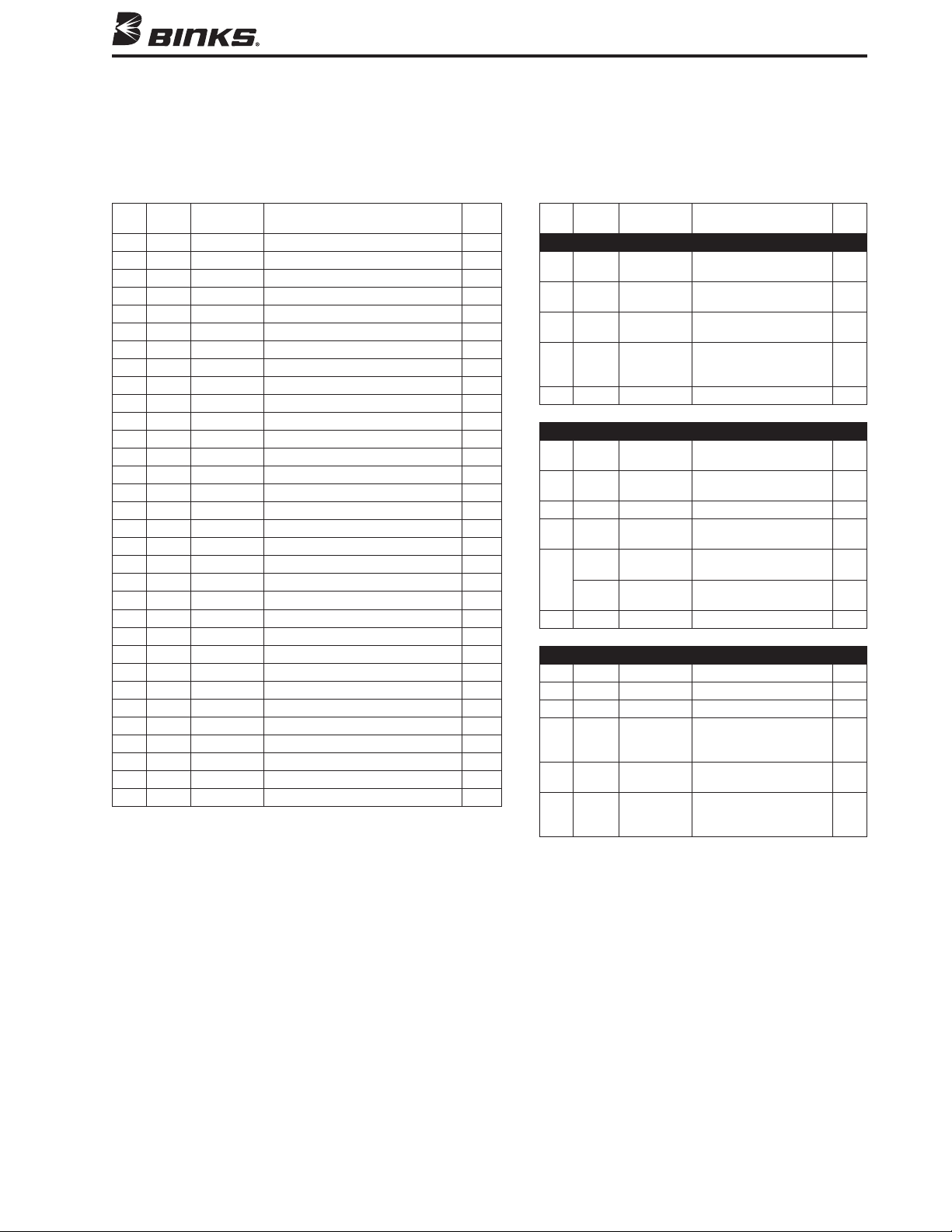
Numbers in parentheses refer to individual
items shown in the “exploded” drawing on
page 4.
cautIon
or scrape fluid or air nozzles. These
and altering their shape will cause
faulty spray.
!
cautIon
silicone since these lubricants can
cause finish defects.
!
WaRnIng
Be sure to follow all safety
precautions described on page 2
before working on the spray gun.
throughout the system and the
power or air supply for the fluid
pump has been disconnected. Always
test the repaired gun for leaks with
low pressure fluid before use.
!
FLAT TIP AIR CAP, CARBIDE TIP
Service symptoms (Flat Tip):
•Coating build-up on air cap or
clogged carbide tip
•Fluidseatassemblynot
sealing properly
1. Depressurize the spray gun.
2. Turn retaining ring (19) counter-
clockwise and remove.
3. Remove air cap (19) and carbide tip
assembly (20) from fluid seat
assembly (21). With the air cap facing
up, apply pressure to carbide tip (20)
and remove from air cap (19).
4. Turn fluid seat assembly (21)
counterclockwise and remove.
5. Service or replace and reassemble in
reverse order.
note
Carbide fluid tip needs to be
oriented properly in the air cap.
The alignment pin in the air cap is
to be properly positioned to the slot
in the carbide tip.
TWIST TIP AIR CAP, CARBIDE
ASSEMBLY
Service symptoms (Twist Tip):
•Coating build-up on air cap
•CloggedTwistTip
Coating build-up:
1. Depressurize the spray gun.
2. Remove air cap (38) from the spray
gun and wash in solvent.
3. Reinstall the air cap (38).
Clogged Twist Tip:
1. Point the spray gun toward booth filter
and away from your body.
2. Rotate Twist Tip 180 degrees to
un-clog the tip.
Service symptoms:
•Fluidleakingfromweepsport
1. Turn rear cap (1) counterclockwise
and remove the piston return spring
from the piston housing (26) and
needle return spring (4).
2. With two 5/16" wrenches (not
supplied with gun), loosen collet
locknut (10) from collet (11).
3. Using a pair of pliers, grip collet (11)
and remove piston assembly (16).
4. Place the 3/8" deep socket (supplied
with gun) over cartridge assembly
(18) and turn counterclockwise.
5. Replace fluid needle (17) or fluid
cartridge assembly (18) and reassemble
in reverse order using the new
components as required.
note
bottomed out on the piston assembly
resting against the piston assembly.
note
If the piston is not positioned
correctly, the fluid-to-air timing will
not work correctly. See pictorial
6. After the piston assembly has been
positioned properly, tighten locknut
(10) to collet (11) “wrench tight”.
REPLACING O-RINGS ON
PISTON ASSEMBLY
Service symptoms:
•Atomizingairnotcyclingoff
•Airnotactuatingfluid
1. Turn end cap (1) counterclockwise
and remove the piston return spring
from the piston housing (26) and
needle return spring (4).
2. With two 5/16" wrenches (not
supplied with gun), loosen collet
locknut (10) from collet (11).
3. Using a pair of pliers, grip collet (11)
and remove piston assembly (16).
4. Replace o-rings (8, 9, 14 & 15) using
Standard Piston O-ring Repair Kit
54-5303 or High Performance Piston
O-ring Repair Kit 54-5307.
5. Apply 41-4458 Teflon-based
lubricant provided in the o-ring repair
kits to o-rings and reassemble in
reverse order.
note
bottomed out on the piston housing
resting against the piston assembly.
note
If the piston is not positioned
correctly, the fluid-to-air timing will
not work correctly. See pictorial
6. After the piston assembly has been
positioned properly, tighten locknut
(10) to collet (11) “wrench tight”.
Service symptoms:
•Fluidtipcloggingorrestriction
influidflow
1. Using a 3/4" inch wrench, turn filter
retainer (35) counterclockwise and
remove.
2. Place a standard screwdriver inside the
cavity where the filter (33) is housed and
dislodge it by lifting up with the
screwdriver. Remove filter and clean or
replace as required. Most of the time you
can dislodge the filter using your finger.
3. Reassemble in reverse order.
note
note
all o-rings before immersing gun in
or subjecting it to a flood-wash of
may induce o-ring swelling beyond
their specification sizes and cause
(continued on page 8)

8
SPRAY GUN
SPRAY GUN
CYLINDER
AIR SOLENOID
(3-WAY)
ATOMIZING AIR
REGULATOR
PLUG
Y
FILTER
CYLINDER AIR
ATOMIZING AIR
CYLINDER
AIR SOLENOID
(3-WAY)
Y
FILTER
ATOMIZING AIR
CYLINDER AIR
FAN AIR
FAN AIR
REGULATOR
ATOMIZING AIR
REGULATOR
GROUND
GROUND
PISTON POSITIONING
Install piston assembly into piston
housing. Be sure all o-rings are
properly lubricated with 41-4458
Teflon-based lubricant provided
with o-ring repair kits.
Piston assembly must be
bottomed out in the piston
housing (approximately 5/8" from
the top of the piston housing).
Lift the collet until it stops and
hold in an upright position while
inserting a 5/16" wrench onto
the collet.
Insert and tighten the collet
locknut using a second 5/16"
wrench and “wrench tighten”.
If properly assembled, bottom
of collet should be 3/16" from
the top of the piston assembly.
Piston Assembly
Piston Housing
Piston Assembly
Collet
Collet Locknut
3/16"
SPRAY GUN
SPRAY GUN
CYLINDER
AIR SOLENOID
(3-WAY)
ATOMIZING AIR
REGULATOR
PLUG
Y
FILTER
CYLINDER AIR
ATOMIZING AIR
CYLINDER
AIR SOLENOID
(3-WAY)
Y
FILTER
ATOMIZING AIR
CYLINDER AIR
FAN AIR
FAN AIR
REGULATOR
ATOMIZING AIR
REGULATOR
GROUND
GROUND
(FOR FLAT TIP APPLICATIONS ONLY)
note
The gun will leak air if the piston is not
adjusted correctly.
FROM INLET MANIFOLD
ASSEMBLY
1. Using a 9/64" Allen wrench (supplied
with gun), turn retaining cap screw
(23) counter-clockwise typical
4 places and remove gun sub module.
2. Mount the new gun module, tightening
the retaining screws (23) “wrench tight”.
This will allow fluid and air passages
to seal with no contamination.
note
O-rings (25 & 29) must be replaced
when replacing gun sub module.

9
(FLAT TIP)
1.750
1/4" O.D. TUBE X
1/8"NPT FITTING
CYLINDER AIR
SIDE PORT
AIR FAN
ADJUSTMENT
1/4"NPT(F)
FAN AIR INLET
1/4"NPT(F)
ATOMIZING AIR INLET
1/2" DIA HOLE
FOR GUN MOUNTING ROD
SET SCREW FOR ROD MOUNT OR
SINGLE BOLT ADAPTER MOUNT
1/4"NPT(F) FLUID
INLET TYPICAL
BOTH SIDES
5 13/16"
.966
1.826
2.700
.735
1.470
3.158
2.306
.402
.402
8-32 X 3/16"
DEEP TYPICAL 8 PLACES
PISTON VENT AND FLUID
BY-PASS WEEP PORT
1.201
1.282
1.375
(WITH TWIST TIP)
1.750
1/4" O.D. TUBE X
1/8"NPT FITTING
CYLINDER AIR
SIDE PORT
AIR FAN
ADJUSTMENT
1/4"NPT(F)
FAN AIR INLET
1/4"NPT(F)
ATOMIZING AIR INLET
1/2" DIA HOLE
FOR GUN MOUNTING ROD
SET SCREW FOR ROD MOUNT OR
SINGLE BOLT ADAPTER MOUNT
1/4"NPT(F) FLUID
INLET TYPICAL
BOTH SIDES
6 7/8"
.966
1.826
2.700
.704
1.470
3.158
2.306
.402
.402
8-32 X 3/16"
DEEP TYPICAL 8 PLACES
PISTON VENT AND FLUID
BY-PASS WEEP PORT
1.201
1.282
1.375

10
STANDARD FLAT TIP SELECTION CHARTS
GPM
FAN CAPACITY
114-00702 TIP ASSEMBLY .007 2 .028
114-00704 TIP ASSEMBLY .007 4 .028
114-00706 TIP ASSEMBLY .007 6 .028
114-00708 TIP ASSEMBLY .007 8 .028
114-00902 TIP ASSEMBLY .009 2 .039
114-00906 TIP ASSEMBLY .009 6 .039
114-00908 TIP ASSEMBLY .009 8 .039
114-00910 TIP ASSEMBLY .009 10 .039
114-00912 TIP ASSEMBLY .009 12 .039
114-01104 TIP ASSEMBLY .011 4 .060
114-01106 TIP ASSEMBLY .011 6 .060
114-01108 TIP ASSEMBLY .011 8 .060
114-01110 TIP ASSEMBLY .011 10 .060
114-01112 TIP ASSEMBLY .011 12 .060
114-01114 TIP ASSEMBLY .011 14 .060
114-01304 TIP ASSEMBLY .013 4 .090
114-01306 TIP ASSEMBLY .013 6 .090
114-01308 TIP ASSEMBLY .013 8 .090
114-01310 TIP ASSEMBLY .013 10 .090
114-01312 TIP ASSEMBLY .013 12 .090
114-01314 TIP ASSEMBLY .013 14 .090
114-01316 TIP ASSEMBLY .013 16 .090
114-01506 TIP ASSEMBLY .015 6 .120
114-01508 TIP ASSEMBLY .015 8 .120
114-01510 TIP ASSEMBLY .015 10 .120
114-01512 TIP ASSEMBLY .015 12 .120
114-01514 TIP ASSEMBLY .015 14 .120
114-01516 TIP ASSEMBLY .015 16 .120
114-01518 TIP ASSEMBLY .015 18 .120
114-01706 TIP ASSEMBLY .017 6 .160
114-01708 TIP ASSEMBLY .017 8 .160
114-01710 TIP ASSEMBLY .017 10 .160
114-01712 TIP ASSEMBLY .017 12 .160
114-01714 TIP ASSEMBLY .017 14 .160
114-01716 TIP ASSEMBLY .017 16 .160
114-01718 TIP ASSEMBLY .017 18 .160
114-01906 TIP ASSEMBLY .019 6 .190
114-01908 TIP ASSEMBLY .019 8 .190
114-01910 TIP ASSEMBLY .019 10 .190
114-01912 TIP ASSEMBLY .019 12 .190
114-01914 TIP ASSEMBLY .019 14 .190
114-01916 TIP ASSEMBLY .019 16 .190
114-01918 TIP ASSEMBLY .019 18 .190
114-02110 TIP ASSEMBLY .021 10 .240
114-02112 TIP ASSEMBLY .021 12 .240
114-02114 TIP ASSEMBLY .021 14 .240
114-02116 TIP ASSEMBLY .021 16 .240
114-02118 TIP ASSEMBLY .021 18 .240
114-02410 TIP ASSEMBLY .024 10 .310
114-02412 TIP ASSEMBLY .024 12 .310
114-02414 TIP ASSEMBLY .024 14 .310
114-02416 TIP ASSEMBLY .024 16 .310
114-02418 TIP ASSEMBLY .024 18 .310
114-02710 TIP ASSEMBLY .027 10 .385
114-02712 TIP ASSEMBLY .027 12 .385
114-02714 TIP ASSEMBLY .027 14 .385
114-02716 TIP ASSEMBLY .027 16 .385
114-02718 TIP ASSEMBLY .027 18 .385
TWIST TIP SELECTION CHARTS
FAN GPM
WIDTH CAPACITY
9-307-75 TWIST TIP 0.007 6 0.05
9-309-75 TWIST TIP 0.009 6 0.09
9-409-75 TWIST TIP 0.009 8 0.09
9-509-75 TWIST TIP 0.009 10 0.09
9-211-75 TWIST TIP 0.011 4 0.12
9-311-75 TWIST TIP 0.011 6 0.12
9-411-75 TWIST TIP 0.011 8 0.12
9-511-75 TWIST TIP 0.011 10 0.12
9-611-75 TWIST TIP 0.011 12 0.12
9-213-75 TWIST TIP 0.013 4 0.18
9-313-75 TWIST TIP 0.013 6 0.18
9-413-75 TWIST TIP 0.013 8 0.18
9-513-75 TWIST TIP 0.013 10 0.18
9-613-75 TWIST TIP 0.013 12 0.18
9-713-75 TWIST TIP 0.013 14 0.18
9-215-75 TWIST TIP 0.015 4 0.24
9-315-75 TWIST TIP 0.015 6 0.24
9-415-75 TWIST TIP 0.015 8 0.24
9-515-75 TWIST TIP 0.015 10 0.24
9-615-75 TWIST TIP 0.015 12 0.24
9-715-75 TWIST TIP 0.015 14 0.24
9-317-75 TWIST TIP 0.017 6 0.31
9-417-75 TWIST TIP 0.017 8 0.31
9-517-75 TWIST TIP 0.017 10 0.31
9-617-75 TWIST TIP 0.017 12 0.31
9-717-75 TWIST TIP 0.017 14 0.31
9-419-75 TWIST TIP 0.019 8 0.38
9-519-75 TWIST TIP 0.019 10 0.38
9-619-75 TWIST TIP 0.019 12 0.38
9-521-75 TWIST TIP 0.021 10 0.47
9-621-75 TWIST TIP 0.021 12 0.47
9-523-75 TWIST TIP 0.023 10 0.57
9-623-75 TWIST TIP 0.023 12 0.57
9-525-75 TWIST TIP 0.025 10 0.67
9-625-75 TWIST TIP 0.025 12 0.67
9-627-75 TWIST TIP 0.027 12 0.74
9-435-75 TWIST TIP 0.035 8 1.31
9-631-75 TWIST TIP 0.031 12 1.03
9-635-75 TWIST TIP 0.035 12 1.31
Fanwidthbasedon2200PSIwithlatex
paint12"fromsurface.Actualresultsmay
vary, depending on material viscosity.
Fanwidthbasedon1000PSIwithwater
12"fromsurface.Actualresultsmay
vary, depending on material viscosity.
FINE FINISH FLAT TIP SELECTION CHARTS
GPM
FAN CAPACITY
9-0909-F FINE FINISH TIP 0.009 9 0.039
9-0911-F FINE FINISH TIP 0.009 11 0.039
9-1109-F FINE FINISH TIP 0.011 9 0.06
9-1111-F FINE FINISH TIP 0.011 11 0.06
9-1113-F FINE FINISH TIP 0.011 13 0.06
9-1115-F FINE FINISH TIP 0.011 15 0.06
9-1309-F FINE FINISH TIP 0.013 9 0.09
9-1311-F FINE FINISH TIP 0.013 11 0.09
9-1313-F FINE FINISH TIP 0.013 13 0.09
9-1315-F FINE FINISH TIP 0.013 15 0.09
9-1509-F FINE FINISH TIP 0.015 9 0.12
9-1511-F FINE FINISH TIP 0.015 11 0.12
9-1513-F FINE FINISH TIP 0.015 13 0.12
9-1515-F FINE FINISH TIP 0.015 15 0.12
9-1517-F FINE FINISH TIP 0.015 17 0.12
9-1709-F FINE FINISH TIP 0.017 9 0.16
9-1711-F FINE FINISH TIP 0.017 11 0.16
9-1713-F FINE FINISH TIP 0.017 13 0.16
9-1715-F FINE FINISH TIP 0.017 15 0.16
9-1717-F FINE FINISH TIP 0.017 17 0.16
Fanwidthbasedon1000PSIwithwater
12"fromsurface.Actualresultsmay
vary, depending on material viscosity.
TWIST TIP NOTE
When switching from flat tip to twist tip, increase pattern
size by 2 inches and use air adjustment to turn down to
desired size.

HOW TO ORDER THE MAG II
WITH MANIFOLD
MAG II Automatic HVLP Spray Gun WITH MANIFOLD,
(Flat Tip)
MAG II Automatic HVLP Spray Gun WITH MANIFOLD,
(Twist Tip)
Spray tips must be ordered separately. Use the spray tip selection chart to
determine orifice size and fan size required.
PART NO. DESCRIPTION
54-4994 Cleaning Kit: includes one standard stiff nylon
pipe cleaning brush, full-size nylon brush, tip
cleaner, and Binks Gunners Mate Lubricant
54-5303 Standard Performance Seal Kit (optional)
54-5396 Piston Collet Repair Kit
54-5307 High Performance Seal Kit (standard in gun)
54-5399 Single Bolt CEFLA Adapter Kit
PART NO. DESCRIPTION
54-1835 100 Mesh Filter Screen
ACCESSORIES
PART NO. DESCRIPTION
41-4458 Teflon O-ring Lube
54-5932-K Twist Tip HVLP Air Cap Test Kit
54-5837-K Flat Tip HVLP Air Cap Test Kit
54-380 Gun Mounting Bracket
FLAT TIP COMPONENTS
PART NO. DESCRIPTION
54-5799-K FLUID SEAT, TUNGSTEN CARBIDE w/GASKET
54-5811-K FLUID SEAT, UHMPE w/GASKET (OPTIONAL)
SPA-98-K5 GASKET (KIT OF 5)
114-XXXXX FLAT TIP
9-XXXX-F FLAT TIP (FINE FINISH)
54-5795-K FLAT TIP HVLP AIRCAP KIT
54-5797-K FLAT TIP LVMP AIRCAP KIT
54-5852 RETAINING RING
54-5794 FLAT TIP GUARD
TWIST TIP COMPONENTS
PART NO. DESCRIPTION
54-5832-K TWIST TIP FLUID SEAT, TUNGSTEN CARBIDE
w/GASKET
54-5833-K TWIST TIP FLUID SEAT, UHMPE w/GASKET
9-XXX-75 TWIST TIP
54-5922-K2 TWIST TIP BRACE (KIT OF 2)
54-5924-K TWIST TIP HVLP AIRCAP KIT
54-5925-K TWIST TIP LVMP AIRCAP KIT
54-5928 RETAINING RING
54-5921 TWIST TIP GUARD
SPA-98-K5 GASKET (KIT OF 5)
HOW TO ORDER THE MAG II
MAG II Automatic HVLP Spray Gun WITHOUT MANIFOLD,
(Flat Tip)
MAG II Automatic HVLP Spray Gun WITHOUT MANIFOLD,
(Twist Tip)
Spray tips must be ordered separately. Use the spray tip selection chart to
determine orifice size and fan size required.
– __ – H
MAG II DESIGNATION

10/12 ©2012 Binks All rights reserved. Printed in U.S.A.
A.
195 Internationale Blvd.
Glendale Heights, IL 60139
630-237-5000
Toll Free Customer Service
and Technical Support
800-992-4657
Toll Free Fax
888-246-5732
WARRANTY
This product is covered by Binks’ 1 Year Limited Warranty.
This manual suits for next models
4
Table of contents
Other Binks Paint Sprayer manuals

Binks
Binks MAG HVLP 4006-1100-0 User manual

Binks
Binks EMG Series User manual

Binks
Binks 2100 SERIES User manual

Binks
Binks HVLP 2001 Installation guide

Binks
Binks SG-2 PLUS 80-600 User manual

Binks
Binks 21 User manual

Binks
Binks M1-G HVLP Troubleshooting guide

Binks
Binks SV100 User manual

Binks
Binks 2100 gw User manual

Binks
Binks Mach 1A HVLP User manual

Binks
Binks 2001SS Manual

Binks
Binks 44-6000 Troubleshooting guide

Binks
Binks HP 4/32 User manual

Binks
Binks AA4400M User manual

Binks
Binks MACH 1 Installation guide

Binks
Binks Mach 1SLA User manual

Binks
Binks 95 User manual

Binks
Binks 7D User manual

Binks
Binks AA4400M User manual

Binks
Binks Model 115 User manual