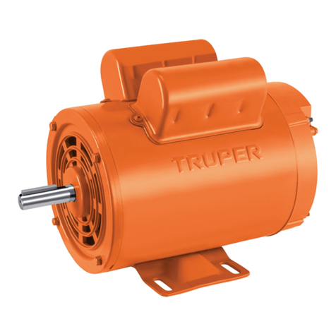
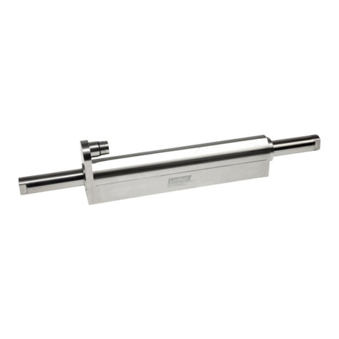
Truper MOE-1/2B User manual

ModelsCodes
MOE-1/2B
MOE-1/4B
Applies for:
102303
102301
LOW SPEED
1 725 RPM
Manual
CAUTION
ENGLISH
ESPAÑOL
Read this manual thoroughly
before using the tool.
1-capacitor
Single-phase
Motor

2
MOE-1/2B
MOE-1/4B
Contents
ENGLISH
CAUTION
Keep this manual for future references.
The illustrations in this manual are for reference
only. They might be different from the real tool.
To gain the best performance of
the tool, prolong the duty life,
make the Warranty valid if
necessary, and to avoid hazards
of fatal injuries please read and
understand this Manual before
using the tool.
Technical Data
Dimensions
Electric requirements
General safety warnings for power tools
Safety warnings for electric motors
Parts
Mounting
Connections
Troubleshooting
Notes
Authorized Service Centers
Warranty Policy
3
3
4
5
6
6
7
8
9
12
13
14

3
Technical Data
56 (NEMA)
IP 21
104 °F
Class F
Speed
1.15
Service factor
Maximum temperature
Insulation class
IP Grade
Frame
Open drip-proof
Type of enclosure
1725 RPM
Voltage
60 Hz
Frequency
115 V / 230 V
MOE-1/2B MOE-1/4B
102301102303
0.372 kW (1/2 Hp) 0.186 kW (1/4 Hp)
Low speed single phase electric motor with 1 capacitor
Code
Description
Rated power
5.2 A / 2.6 A8.8 A / 4.4 A
Current
9 kg 7 kg
Weight
5.6 A / 2.8 A9.4 A / 4.7 A
Current operating
at service factor
Capacitor with centrifugal switch
Start type
Shaft diameter
Shaft wedge 1 3/8” x 3/16” (3.5 cm x 0.5 cm)
5/8” (16 mm)
10.6” 11.4”
Length (A)
A
4.8”
6.2”
8.4”
1.1”
0.65”
r: 0.16”
3”
1.8”
3.5”
Dimensions
Base
ENGLISH

4ENGLISH
From 0 A up to 10 A
From 10 A up to 13 A
From 13 A up to 15 A
From 15 A up to 20 A
18 AWG (**)
16 AWG
14 AWG
8 AWG
16 AWG
14 AWG
12 AWG
6 AWG
3
(one grounded)
from 5.9’ to 49.2’ | higher than 49.2’
Ampere
capacity Number of
conductors (*)
Extension gauge
From 0 A up to 11 A
From 11 A up to 15 A
From 15 A up to 17 A
From 17 A up to 23 A
18 AWG (**)
16 AWG
14 AWG
10 AWG
16 AWG
14 AWG
12 AWG
8 AWG
3
(one grounded)
from 5.9’ to 49.2’ | higher than 49.2’
Ampere
capacity Number of
conductors (*)
Extension gauge
The equipment must be grounded to
prevent electric shock.
• Connect the plug into a properly grounded outlet. Not all
outlets are properly grounded, if you are not sure, check
with a qualified electrician.
• If the outlet available for the equipment is a 2-pole
(2-hole) outlet, DO NOT REMOVE OR ALTER THE
GROUND CONDUCTOR OF YOUR PLUG FOR ANY
REASON.
• Connection to the power source must
be made by an electrical professional, following one of the
diagrams on page 8.
• Use a separate electrical circuit for the
motor. This circuit must not have conductors with a gauge
smaller than 12 AWG, and must be protected with a 20 A
to 30 A time delay fuse depending on the current of each
model.
• Before connecting the motor to the power line, make
sure that the voltage is equal to that indicated on the
motor nameplate. Operating with a lower voltage will
damage the motor.
• The ground wire gauge must not be
smaller than the power supply wire gauge.
• It is recommended that the motor be supplied with a
circuit that includes a residual current circuit breaker with
a rated current of no more than 30 mA
• The motors have a built-in thermal protector to protect
them against overheating.
When using an
extension cord, make sure the
gauge is sufficient for the current
the equipment will draw.
Under-gauging will result in line
voltage drops, loss of power and
motor overheating. The following
tables show the correct gauges to
use depending on the length of the
cable and the ampere rating
indicated on the tool's nameplate.
If in doubt use the next higher
gauge.
All wiring, electrical connections and grounding of the system must comply with MEXICAN
OFFICIAL NOM-001-SEDE, ELECTRICAL INSTALLATIONS (UTILIZATION) or local codes and ordinances.
A qualified electrician must be employed.
230 Volts
115 Volts
* One of the conductors must be a grounding conductor. All conductors are of the same designation (gauge) including the grounding conductor.
** It is allowed to use it as long as the extensions themselves are provided with an overcurrent protection device.
AWG = American Wire Gauge. Reference: NMX-J-195-ANCE
Electric requirements
CAUTION
CAUTION
CAUTION
CAUTION
WARNING
WARNING

5
ENGLISH
General power tool
safety warnings
Work area
Keep your work area clean, and well lit.
Cluttered and dark areas may cause accidents.
Never use the tool in explosive atmospheres, such as in the
presence of flammable liquids, gases or dust.
Sparks generated by power tools may ignite the flammable material.
Keep children and bystanders at a safe distance while operating
the tool.
Distractions may cause loosing control.
Electrical Safety
The tool plug must match the power outlet. Never modify
the plug in any way. Do not use any adapter plugs with
grounded power tools.
Modified plugs and different power outlets increase the risk of electric shock.
Avoid body contact with grounded surfaces, such as pipes,
radiators, electric ranges and refrigerators.
The risk of electric shock increases if your body is grounded.
Do not expose the tool to rain or wet conditions.
Water entering into the tool increases the risk of electric shock.
Do not force the cord. Never use the cord to carry, lift or unplug
the tool. Keep the cord away from heat, oil, sharp edges or
moving parts.
Damaged or entangled cords increase the risk of electric shock.
When operating a tool outdoors, use an extension cord suitable
for outdoor use.
Using an adequate outdoor extension cord reduces the risk of electric shock.
If operating the tool in a damp location cannot be avoided, use
a ground fault circuit interrupter (GFCI) protected supply.
Using a GFCI reduces the risk of electric shock.
Personal safety
Stay alert, watch what you are doing and use common sense
when operating a tool. Do not use a power tool while you are
tired or under the influence of drugs, alcohol or medication.
A moment of distraction while operating the tool may result in personal injury.
Use personal protective equipment. Always wear eye
protection.
Protective equipment such as safety glasses, anti-dust mask, non-skid shoes,
hard hats and hearing protection used in the right conditions significantly
reduce personal injury.
Prevent unintentional starting up. Ensure the switch is in the
“OFF” position before connecting into the power source and /
or battery as well as when carrying the tool.
Transporting power tools with the finger on the switch or connecting power
tools with the switch in the “ON” position may cause accidents.
Remove any wrench or vice before turning the power tool on.
Wrenches or vices left attached to rotating parts of the tool may result in personal
injury.
Do not overreach. Keep proper footing and balance at all times.
This enables a better control on the tool during unexpected situations.
Dress properly. Do not wear loose clothing or jewelry. Keep
hair, clothes and gloves away from the moving parts.
Loose clothes or long hair may get caught in moving parts.
If you have dust extraction and recollection devices connected
onto the tool, inspect their connections and use them correctly.
Using these devices reduce dust-related risks.
Power Tools Use and Care
Do not force the tool. Use the adequate tool for your
application.
The correct tool delivers a better and safer job at the rate for which it was designed.
Do not use the tool if the switch is not working properly.
Any power tool that cannot be turned ON or OFF is dangerous and should be
repaired before operating.
Disconnect the tool from the power source and / or battery
before making any adjustments, changing accessories or
storing.
These measures reduce the risk of accidentally starting the tool.
Store tools out of the reach of children. Do not allow persons
that are not familiar with the tool or its instructions to
operate the tool.
Power tools are dangerous in the hands of untrained users.
Service the tool. Check the mobile parts are not misaligned or
stuck. There should not be broken parts or other conditions that
may affect its operation. Repair any damage before using the
tool.
Most accidents are caused due to poor maintenance to the tools.
Keep the cutting accessories sharp and clean.
Cutting accessories in good working conditions are less likely to bind and are
easier to control.
Use the tool, components and accessories in accordance with
these instructions and the projected way to use it for the type of
tool when in adequate working conditions.
Using the tool for applications different from those it was designed for, could
result in a hazardous situation.
Service
Repair the tool in a Authorized Service Center
using only identical spare parts.
This will ensure that the safety of the power tool is maintained.
Children or people with reduced physical; sensory or mental
capabilities shall not operate the tool, neither inexperienced
people or without knowledge in the use of the tool, unless
supervised by a person responsible of their safety or if receiving
previous instructions about the tool operation.
Children shall be kept under supervision to double-check they will not play
with the tool. Tight supervision shall be used with children or disabled
persons to prevent from using or being close to any household tool.
WARNING! Read carefully all safety warnings and instruction listed below. Failure to comply with any of
these warnings may result in electric shock, fire and / or severe damage. Save all warnings and instructions for
future references.
This tool is in compliance with
the Official Mexican Standard
(NOM - Norma Oficial Mexicana).

6
Ventilation
slots
Shaft
Name
plate
Starting
capacitor
Ventilation
slots
Power cord
inlet
Cable outlet
to ground
Connection
panel cover
Base with
fixing holes
Shaft
key
ENGLISH
Safety warnings
for electric motors
Parts
• Before installing or operating the
equipment, disconnect from any power source to avoid
electric shock and/or burns due to short circuits.
• Do not touch the bare (unprotected)
terminal. An electric shock will result.
• Do not touch any live lines simultaneously,
an electric shock will result.
• Do not install or handle equipment without
proper protective equipment or with wet hands.
• Do not install, connect, disconnect or handle the equipment
under load. With the exception of socket outlets, never
connect pluggable equipment when it is energized.
• If you do not have or doubt that you have the appropriate
technical knowledge, never install or handle the equipment.
• Before installation, be sure to read these operating
instructions carefully to ensure correct operation.
• Installation, maintenance and inspection of
electrical equipment must be carried out by qualified
technicians with special knowledge.
• Do not install the equipment in an environment with shock,
high temperature, humidity, dust, corrosive gases, excessive
vibration, etc. to avoid fire accidents and/or equipment
malfunction.
• Use electrical equipment with the voltage and current ratings
shown on the nameplate, otherwise it may cause
malfunctions and even dangerous situations.
• Tighten the terminal screws to the proper torque to prevent
overheating.
• Make sure that the equipment and the connection cables
are securely fastened.
• Always use terminals on the cables to which the equipment
is connected, these must be suitable for the load to be
supported.
• If there are several terminals in close proximity, each
terminal or conductor pole must be connected in parallel.
• If the equipment is equipped with grounding terminals,
make sure they are grounded.
• Always connect the equipment according to the indications
and diagrams provided by the manufacturer.
• Never exceed the operating ranges indicated by the
manufacturer.
• Do not modify the equipment.
• When the equipment is to be disposed of, it should be
disposed of as industrial waste.
• Do not connect aluminum terminals and conductors to the
switch directly.
• Always comply with the regulations in force at the place of
installation.
CAUTION
CAUTION
CAUTION
CAUTION
CAUTION

7
A
1 2
3
B
ENGLISH
Mounting
• Before mounting the motor remove
the plastic cover from the shaft and rotate it by hand.
The motor shaft must rotate freely.
• The motor is mounted by means of its rigid base,
which must be fixed on a flat surface prepared for
installation according to the dimension table shown on
page 3, using four 5/16” (8 mm) diameter screws or
threaded bolts.
• If mounting on steel plate (A) it is recommended that
the thickness of the steel plate be no less than the bolt
diameter.
• For mounting on concrete or concrete slab (B), a free
bolt thread length of not less than 7/16” (11 mm) is
recommended.
• Use a drop level or laser to validate motor levelness.
If the motor is not level, use calibrated adjustment
blades to shim the motor base and correct any
deviations in flatness between surfaces.
Motor mounting
• The motor shaft includes a 3/16” (0.5 cm) x 1-3/8”
(3.5 cm) key to transmit motion to the coupling.
• Depending on the application, the shaft can be coupled
to the machine in three ways:
1. Gear or sprocket coupling.
2. Coupling by pulleys or flywheel.
3. Coupling by connecting joint.
• In any of the cases, a correct alignment of the couplings
must be ensured to reduce the vibration of the assembly
between the motor and the driven machine and to
extend the life of the bearings and avoid damage to the
motor shaft.
• The use of flexible couplings, capable of absorbing
small alignment deviations inherent to the installation
during operation of the equipment, is recommended.
• In applications of coupling by means of connecting
joints, the motor must be aligned both axially and radially
as shown in the image.
Shaft joint
CAUTION

Ground
8
Voltage configuration
Direction of rotation configuration
Connections
• To perform the wiring, make sure
that the lines are not energized.
• Remove the rear cover (A) to access the connection
panel.
• Make the connections according to the voltage
configuration that best suits your needs.
• When using any of the configurations shown above,
the motor shaft rotates clockwise as viewed from the
connection panel. To reverse counterclockwise rotation:
interchange the red and brown wires.
Ground
Black
Blue
Red
Orange
Brown
White
Line 1
Line 2
230 Volts115 Volts
1
2
3
4
Line 1
Line 2
1
2
3
4
Black
Blue
Red
Orange
Brown
White
A
ENGLISH
Mounting
• For belt and chain drive applications, verify that the
centers of the drive and driven pulleys and/or sprockets
are aligned with each other as shown.
• Proper alignment and mounting will reduce motor
noise and workload vibration.
CAUTION

9
Troubleshooting
ENGLISH
The engine takes a
long time to
accelerate.
Motor does not start
after initial
installation.
The shaft rotates in
the opposite
direction.
The overload
protector trips
continuously.
Engine has been
running and then will
not start.
• Defective bearings.
• Defective capacitor.
• Faulty stationary switch.
• Voltage too low.
• The fan guard is bent and in contact with
the fan.
• The motor is damaged and the rotor is
hitting the stator.
• The motor has bad wiring.
• Wiring configured to rotate in the
opposite direction.
• Ambient temperature too high.
• The winding is shorted or grounded.
• Protector may be defective.
• Excessive load.
• The motor or its capacitor may have
failed.
• The stator is shorted or has gone to
ground. The motor will hum and the circuit
breaker or fuse will trip.
• The starter switch has failed.
• The fuse or circuit breaker has tripped.
• Motor overloaded or load stuck.
• The bearing must be replaced.
• Refer to a Authorized Service
Center for repair.
• Inspect and repair the switch contacts and connections.
• Make sure the voltage is within 10% of the motor
rating. If not, contact the power company or check to see
if other equipment is drawing power away from the
motor.
• Refer to a Authorized Service
Center for repair.
• Check that the motor is correctly wired according to the
information supplied with the motor.
• Rewire the motor according to the configuration
diagram on page 8.
• Check that the motor receives sufficient air for proper
cooling. The motor is designed to operate below 104 °F
Note: A properly running motor may be hot to the touch.
• Inspect the stator for defects or loose or cut wires that
may cause it to ground.
• Refer to a Authorized Service
Center for repair.
• Verify that the load is not jammed. If the motor is a
a replacement, verify that the rating is the same as the
old motor. If the old motor was a special design, a stock
motor may not be able to match the performance.
Remove the load from the motor and inspect the
amperage draw of the motor under load. It should be
less than the full load rating stamped on the nameplate.
• First discharge the capacitor. To check the capacitor, set
the voltmeter to the RX100 scale and touch its probes to
the capacitor terminals. If the capacitor is OK, the needle
will jump to zero ohms and back up again. A steady zero
ohms indicates a short circuit; a steady high ohm
indicates an open circuit.
• Disassemble the motor and inspect the winding and
internal connections. A burned stator will show a burn
mark. The motor must be replaced or the stator
rewound.
• Disassemble the motor and inspect the centrifugal and
stationary switches. The centrifugal switch weights should
move freely in and out. Make sure the switch is not loose
on the shaft. Inspect the contacts and connections of the
stationary switch. Replace the switch if the contacts are
burned or pitted
• Replace the fuse or reset the circuit breaker.
• Inspect to see that the load is free. Check motor amp
draw against nameplate rating.
Problem Cause Solution

Troubleshooting
10 ENGLISH
Motor runs, but shuts
off.
The motor vibrates.
Run capacitor failure.
Starting capacitors
are constantly failing.
A loud rubbing or
squeaking noise is
produced at start-up.
• Voltage drops.
• Load increase.
• Unbalanced load.
• Unbalanced rotor.
• Defective motor bearings.
• Motor misaligned with load.
• Too much backlash at motor ends.
• Defective windings.
• Possible power surge in the motor caused
by lightning or other high transient voltage.
• Ambient temperature is too high.
• The motor starts too often.
• Motor is not coming up to speed fast
enough.
• The starter switch may be defective,
preventing the motor from coming out of
the starter winding.
• Motor voltage is too low.
• The rotor may be hitting the stator.
• If the voltage is less than 10% of the motor rating,
contact the power company.
• Check to see if any other equipment is drawing
power from the motor and if the motor is running on
an extension cord. Verify that the extension cord is the
proper gauge for the motor current.
• Remove the load from the motor for inspection.
Verify that the shaft is not bent. Rule of thumb:
0.001”deflection per inch of shaft length.
• Remove the load from the motor to inspect it. If it
feels rough and vibrates but the bearings are OK, the
rotor may have been improperly balanced at the
factory. Refer to a Authorized
Service Center for repair.
• If the bearings are bad, you will hear a noise or feel a
roughness. Go to a Authorized
Service Center to replace the bearings. Add grease if
the bearings have fittings.
• Realign the load.
• With the motor disconnected from power, rotate the
shaft. It should move, but with some resistance. If the
shaft moves in and out freely, this indicates a preload
problem and the bearings may need additional shims.
• Check to see if the winding is shorted or open. Amps
may also be high. Refer to a Au-
thorized Service Center for repair.
• This is a common problem. Install an over voltage
protector or motor protector relay.
• Verify that the ambient temperature does not exceed
the motor nameplate.
• Check the duty cycle. Capacitor manufacturers
recommend no more than 20 starts of three-second.
Install a capacitor with a higher voltage rating or add a
bleeder resistor to the capacitor.
• The motor may not be properly sized. Check the time
it takes for the motor to reach speed. Most
single-phase motors with starting capacitors should
reach speed in three seconds. If not, the capacitors
may be failing.
• Replace the switch.
• Verify that the motor voltage is within 10% of the
nameplate value.
• Make sure that the motor has not been damaged
during transport.
• Damage to the frame may not be repairable. If you
cannot see physical damage, inspect the motor rotor
and stator for scuff marks. If there are signs of scuffing,
the motor should be replaced. Sometimes, simply
disassembling and reassembling the motor will
eliminate the scuffing.
Sometimes end bells become misaligned during
shipping.
Problem Cause Solution

11
Troubleshooting
ENGLISH
Bearings fail
continuously.
Elevated or
abnormal noise.
• High ambient temperature.
• Motor load may be excessive or
unbalanced.
• Defect of the components of the driven
machine.
• Misaligned base or unlevel motor.
• Incorrect motor rotation direction.
• Loose fixing screws.
• Deteriorated bearings.
• If the engine is operated in a warm environment, a
different type of bearing grease may be required. Contact
a Authorized Service Center
for a recommendation of the proper type of grease.
• In addition to checking the load, also inspect the drive
belt tension to make sure it is not tight or perhaps too
high. An unbalanced tip will also cause the bearings to
fail.
• Check the power transmission of the applied load.
• Align and level the motor and load.
• Reverse the direction of rotation of the load.
• Tighten the fixing bolts.
• Replace bearings.
Problem Cause Solution
If problems persist despite performing the recommended corrective actions,
contact a Authorized Service Center.

12
Notes
ENGLISH

13
ENGLISH
Authorized Service Centers
In the event of any problem contacting a Truper Authorized Service Center, please see our webpage www.truper.com
to get an updated list, or call our toll-free numbers 800 690-6990 or 800-018-7873 to get information about the
nearest Service Center.
AGUASCALIENTES
BAJA
CALIFORNIA
BAJA
CALIFORNIA SUR
CAMPECHE
CHIAPAS
CHIHUAHUA
CIUDAD DE
MÉXICO
COAHUILA
COLIMA
DURANGO
ESTADO DE
MÉXICO
GUANAJUATO
GUERRERO
HIDALGO
JALISCO
MICHOACÁN
MORELOS
NAYARIT
NUEVO LEÓN
OAXACA
PUEBLA
QUERÉTARO
QUINTANA ROO
SAN LUIS
POTOSÍ
SINALOA
SONORA
TABASCO
TAMAULIPAS
TLAXCALA
VERACRUZ
YUCATÁN
DE TODO PARA LA CONSTRUCCIÓN
GRAL. BARRAGÁN #1201, COL. GREMIAL, C.P. 20030,
AGUASCALIENTES, AGS. TEL.: 449 994 0537
SUCURSAL TIJUANA
AV. LA ENCANTADA, LOTE #5, PARQUE INDUSTRIAL EL
FLORIDO II, C.P 22244, TIJUANA, B.C.
TEL.: 664 969 5100
FIX FERRETERÍAS
FELIPE ÁNGELES ESQ. RUIZ CORTÍNEZ S/N, COL. PUEBLO
NUEVO, C.P. 23670, CD. CONSTITUCIÓN, B.C.S.
TEL.: 613 132 1115
TORNILLERÍA Y FERRETERÍA AAA
AV. ÁLVARO OBREGÓN #324, COL. ESPERANZA
C.P. 24080 CAMPECHE, CAMP. TEL.: 981 815 2808
FIX FERRETERÍAS
AV. CENTRAL SUR #27, COL. CENTRO, C.P. 30700,
TAPACHULA, CHIS. TEL.: 962 118 4083
SUCURSAL CHIHUAHUA
AV. SILVESTRE TERRAZAS #128-11, PARQUE INDUSTRIAL
BAFAR, CARRETERA MÉXICO CUAUHTÉMOC, C.P. 31415,
CHIHUAHUA, CHIH. TEL. 614 434 0052
FIX FERRETERÍAS
EL MONSTRUO DE CORREGIDORA, CORREGIDORA # 22,
COL. CENTRO, C.P. 06060, CUAUHTÉMOC, CDMX.
TEL: 55 5522 5031 / 5522 4861
SUCURSAL TORREÓN
CALLE METAL MECÁNICA #280, PARQUE INDUSTRIAL
ORIENTE, C.P. 27278, TORREÓN, COAH.
TEL.: 871 209 68 23
BOMBAS Y MOTORES BYMTESA DE MANZANILLO
BLVD. MIGUEL DE LA MADRID #190, COL. 16 DE
SEPTIEMBRE, C.P. 28239, MANZANILLO, COL.
TEL.: 314 332 1986 / 332 8013
TORNILLOS ÁGUILA, S.A. DE C.V.
MAZURIO #200, COL. LUIS ECHEVERRÍA, DURANGO,
DGO.TEL.: 618 817 1946 / 618 818 2844
SUCURSAL CENTRO JILOTEPEC
PARQUE INDUSTRIAL # 1, COL. PARQUE INDUSTRIAL
JILOTEPEC, JILOTEPEC, EDO. DE MÉX. C.P. 54257
TEL: 761 782 9101 EXT. 5728 Y 5102
CÍA. FERRETERA NUEVO MUNDO S.A. DE C.V.
AV. MÉXICO - JAPÓN #225, CD. INDUSTRIAL, C.P. 38010,
CELAYA, GTO. TEL.: 461 617 7578 / 79 / 80 / 88
CENTRO DE SERVICIO ECLIPSE
CALLE PRINCIPAL MZ.1 LT. 1, COL. SANTA FE, C.P. 39010,
CHILPANCINGO, GRO. TEL.: 747 478 5793
FERREPRECIOS S.A. DE C.V.
LIBERTAD ORIENTE #304 LOCAL 30, INTERIOR DE PASAJE
ROBLEDO, COL. CENTRO, C.P. 43600, TULANCINGO,
HGO. TEL.: 775 753 6615 / 775 753 6616
SUCURSAL GUADALAJARA
AV. ADOLFO B. HORN # 6800, COL: SANTA CRUZ DEL
VALLE, C.P.: 45655, TLAJOMULCO DE ZUÑIGA, JAL.
TEL.: 33 3606 5285 AL 90
FIX FERRETERÍAS
AV. PASEO DE LA REPÚBLICA #3140-A, COL.
EX-HACIENDA DE LA HUERTA, C.P. 58050, MORELIA,
MICH. TEL.: 443 334 6858
FIX FERRETERÍAS
CAPITÁN ANZURES #95, ESQ. JOSÉ PERDIZ, COL.
CENTRO, C.P. 62740, CUAUTLA, MOR.
TEL.: 735 352 8931
HERRAMIENTAS DE TEPIC
MAZATLAN #117, COL. CENTRO, C.P. 63000, TEPIC, NAY.
TEL.: 311 258 0540
SUCURSAL MONTERREY
CARRETERA LAREDO #300, 1B MONTERREY PARKS,
COLONIA PUERTA DE ANÁHUAC, C.P. 66052, ESCOBEDO,
NUEVO LEÓN, TEL.: 81 8352 8791 / 81 8352 8790
FIX FERRETERÍAS
AV. 20 DE NOVIEMBRE #910, COL. CENTRO, C.P. 68300,
TUXTEPEC, OAX. TEL.: 287 106 3092
SUCURSAL PUEBLA
AV PERIFÉRICO #2-A, SAN LORENZO ALMECATLA,
C.P. 72710, CUAUTLACINGO, PUE.
TEL.: 222 282 8282 / 84 / 85 / 86
ARU HERRAMIENTAS S.A DE C.V.
AV. PUERTO DE VERACRUZ #110, COL. RANCHO DE
ENMEDIO, C.P. 76842, SAN JUAN DEL RÍO, QRO.
TEL.: 427 268 4544
FIX FERRETERÍAS
CARRETERA FEDERAL MZ. 46 LT. 3 LOCAL 2, COL EJIDAL,
C.P. 77710 PLAYA DEL CARMEN, Q.R.
TEL.: 984 267 3140
FIX FERRETERÍAS
AV. UNIVERSIDAD #1850, COL. EL PASEO, C.P. 78320,
SAN LUIS POTOSÍ, S.L.P. TEL.: 444 822 4341
SUCURSAL CULIACÁN
AV. JESÚS KUMATE SUR #4301, COL. HACIENDA DE LA
MORA, C.P. 80143, CULIACÁN, SIN.
TEL.: 667 173 9139 / 173 8400
FIX FERRETERÍAS
CALLE 5 DE FEBRERO #517, SUR LT. 25 MZ. 10, COL.
CENTRO, C.P. 85000, CD. OBREGÓN, SON.
TEL.: 644 413 2392
SUCURSAL VILLAHERMOSA
CALLE HELIO LOTES 1, 2 Y 3 MZ. #1, COL. INDUSTRIAL,
2A ETAPA, C.P. 86010, VILLAHERMOSA, TAB.
TEL.: 993 353 7244
VM ORINGS Y REFACCIONES
CALLE ROSITA #527 ENTRE 20 DE NOVIEMBRE Y GRAL.
RODRÍGUEZ, FRACC. REYNOSA, C.P. 88780, REYNOSA,
TAMS. TEL.: 899 926 7552
SERVICIOS Y HERRAMIENTAS INDUSTRIALES
PABLO SIDAR #132, COL . BARRIO DE SAN BARTOLOMÉ,
C.P. 90970, SAN PABLO DEL MONTE, TLAX.
TEL.: 222 271 7502
LA CASA DISTRIBUIDORA TRUPER
BLVD. PRIMAVERA. ESQ. HORTENSIA S/N, COL.
PRIMAVERA C.P. 93308, POZA RICA, VER.
TEL.: 782 823 8100 / 826 8484
SUCURSAL MÉRIDA
CALLE 33 #600 Y 602, LOCALIDAD ITZINCAB Y MULSAY,
MPIO. UMÁN, C.P. 97390, MÉRIDA, YUC.
TEL.: 999 912 2451

14 www.truper.com
06-2022
MOE-1/2B
MOE-1/4B
102303
102301
ENGLISH
1
YEAR
Warranty
policy
Stamp of the business. Delivery date:
Code Model Brand
Warranty. Duration: 1 year. Coverage: parts, components and workmanship against manufacturing or
operating defects, except if used under conditions other than normal; when it was not operated in accordance
with the instructive; was altered or repaired by personnel not authorized by Truper®. To make the warranty
valid, present the product, stamped policy or invoice or receipt or voucher, in the establishment where you
bought it or in Corregidora 22, Centro, Cuauhtémoc, CDMX, 06060, where you can also purchase parts,
components, consumables and accessories. It includes the costs of transportation of the product that derive
from its fulfillment of its service network. . Phone number 800-018-7873. Made in China. Imported by Truper,
S.A. de C.V. Parque Industrial 1, Parque Industrial Jilotepec, Jilotepec, Edo. de Méx. C.P. 54257, Phone number
761 782 9100.

14 ESPAÑOL
1
AÑO
Póliza de
Garantía
www.truper.com
06-2022
Códigos Modelos Marca
Sello del establecimiento comercial. Fecha de entrega:
MOE-1/2B
MOE-1/4B
102303
102301
Garantía. Duración: 1 año. Cobertura: piezas, componentes y mano de obra contra defectos de fabricación o
funcionamiento, excepto si se usó en condiciones distintas a las normales; cuando no fue operado conforme
instructivo; fue alterado o reparado por personal no autorizado por Truper®. Para hacer efectiva la garantía
presente el producto, póliza sellada o factura o recibo o comprobante, en el establecimiento donde lo compró
o en Corregidora 22, Centro, Cuauhtémoc, CDMX, 06060, donde también podrá adquirir partes, componentes,
consumibles y accesorios. Incluye los gastos de transportación del producto que deriven de su cumplimiento de
su red de servicio. Tel. 800-018-7873. Made in/Hecho en China. Importador Truper, S.A. de C.V. Parque
Industrial 1, Parque Industrial Jilotepec, Jilotepec, Edo. de Méx. C.P. 54257, Tel. 761 782 9100.

13
Centros de Servicio Autorizados
ESPAÑOL
En caso de tener algún problema para contactar un Centro de Servicio Autorizado Truper
®
consulte nuestra página
www.truper.com donde obtendrá un listado actualizado, o llame al: 800 690 6990 u800-018-7873 donde le
informarán cuál es el Centro de Servicio más cercano.
AGUASCALIENTES
BAJA
CALIFORNIA
BAJA
CALIFORNIA SUR
CAMPECHE
CHIAPAS
CHIHUAHUA
CIUDAD DE
MÉXICO
COAHUILA
COLIMA
DURANGO
ESTADO DE
MÉXICO
GUANAJUATO
GUERRERO
HIDALGO
JALISCO
MICHOACÁN
MORELOS
NAYARIT
NUEVO LEÓN
OAXACA
PUEBLA
QUERÉTARO
QUINTANA ROO
SAN LUIS
POTOSÍ
SINALOA
SONORA
TABASCO
TAMAULIPAS
TLAXCALA
VERACRUZ
YUCATÁN
DE TODO PARA LA CONSTRUCCIÓN
GRAL. BARRAGÁN #1201, COL. GREMIAL, C.P. 20030,
AGUASCALIENTES, AGS. TEL.: 449 994 0537
SUCURSAL TIJUANA
AV. LA ENCANTADA, LOTE #5, PARQUE INDUSTRIAL EL
FLORIDO II, C.P 22244, TIJUANA, B.C.
TEL.: 664 969 5100
FIX FERRETERÍAS
FELIPE ÁNGELES ESQ. RUIZ CORTÍNEZ S/N, COL. PUEBLO
NUEVO, C.P. 23670, CD. CONSTITUCIÓN, B.C.S.
TEL.: 613 132 1115
TORNILLERÍA Y FERRETERÍA AAA
AV. ÁLVARO OBREGÓN #324, COL. ESPERANZA
C.P. 24080 CAMPECHE, CAMP. TEL.: 981 815 2808
FIX FERRETERÍAS
AV. CENTRAL SUR #27, COL. CENTRO, C.P. 30700,
TAPACHULA, CHIS. TEL.: 962 118 4083
SUCURSAL CHIHUAHUA
AV. SILVESTRE TERRAZAS #128-11, PARQUE INDUSTRIAL
BAFAR, CARRETERA MÉXICO CUAUHTÉMOC, C.P. 31415,
CHIHUAHUA, CHIH. TEL. 614 434 0052
FIX FERRETERÍAS
EL MONSTRUO DE CORREGIDORA, CORREGIDORA # 22,
COL. CENTRO, C.P. 06060, CUAUHTÉMOC, CDMX.
TEL: 55 5522 5031 / 5522 4861
SUCURSAL TORREÓN
CALLE METAL MECÁNICA #280, PARQUE INDUSTRIAL
ORIENTE, C.P. 27278, TORREÓN, COAH.
TEL.: 871 209 68 23
BOMBAS Y MOTORES BYMTESA DE MANZANILLO
BLVD. MIGUEL DE LA MADRID #190, COL. 16 DE
SEPTIEMBRE, C.P. 28239, MANZANILLO, COL.
TEL.: 314 332 1986 / 332 8013
TORNILLOS ÁGUILA, S.A. DE C.V.
MAZURIO #200, COL. LUIS ECHEVERRÍA, DURANGO,
DGO.TEL.: 618 817 1946 / 618 818 2844
SUCURSAL CENTRO JILOTEPEC
PARQUE INDUSTRIAL # 1, COL. PARQUE INDUSTRIAL
JILOTEPEC, JILOTEPEC, EDO. DE MÉX. C.P. 54257
TEL: 761 782 9101 EXT. 5728 Y 5102
CÍA. FERRETERA NUEVO MUNDO S.A. DE C.V.
AV. MÉXICO - JAPÓN #225, CD. INDUSTRIAL, C.P. 38010,
CELAYA, GTO. TEL.: 461 617 7578 / 79 / 80 / 88
CENTRO DE SERVICIO ECLIPSE
CALLE PRINCIPAL MZ.1 LT. 1, COL. SANTA FE, C.P. 39010,
CHILPANCINGO, GRO. TEL.: 747 478 5793
FERREPRECIOS S.A. DE C.V.
LIBERTAD ORIENTE #304 LOCAL 30, INTERIOR DE PASAJE
ROBLEDO, COL. CENTRO, C.P. 43600, TULANCINGO,
HGO. TEL.: 775 753 6615 / 775 753 6616
SUCURSAL GUADALAJARA
AV. ADOLFO B. HORN # 6800, COL: SANTA CRUZ DEL
VALLE, C.P.: 45655, TLAJOMULCO DE ZUÑIGA, JAL.
TEL.: 33 3606 5285 AL 90
FIX FERRETERÍAS
AV. PASEO DE LA REPÚBLICA #3140-A, COL.
EX-HACIENDA DE LA HUERTA, C.P. 58050, MORELIA,
MICH. TEL.: 443 334 6858
FIX FERRETERÍAS
CAPITÁN ANZURES #95, ESQ. JOSÉ PERDIZ, COL.
CENTRO, C.P. 62740, CUAUTLA, MOR.
TEL.: 735 352 8931
HERRAMIENTAS DE TEPIC
MAZATLAN #117, COL. CENTRO, C.P. 63000, TEPIC, NAY.
TEL.: 311 258 0540
SUCURSAL MONTERREY
CARRETERA LAREDO #300, 1B MONTERREY PARKS,
COLONIA PUERTA DE ANÁHUAC, C.P. 66052, ESCOBEDO,
NUEVO LEÓN, TEL.: 81 8352 8791 / 81 8352 8790
FIX FERRETERÍAS
AV. 20 DE NOVIEMBRE #910, COL. CENTRO, C.P. 68300,
TUXTEPEC, OAX. TEL.: 287 106 3092
SUCURSAL PUEBLA
AV PERIFÉRICO #2-A, SAN LORENZO ALMECATLA,
C.P. 72710, CUAUTLACINGO, PUE.
TEL.: 222 282 8282 / 84 / 85 / 86
ARU HERRAMIENTAS S.A DE C.V.
AV. PUERTO DE VERACRUZ #110, COL. RANCHO DE
ENMEDIO, C.P. 76842, SAN JUAN DEL RÍO, QRO.
TEL.: 427 268 4544
FIX FERRETERÍAS
CARRETERA FEDERAL MZ. 46 LT. 3 LOCAL 2, COL EJIDAL,
C.P. 77710 PLAYA DEL CARMEN, Q.R.
TEL.: 984 267 3140
FIX FERRETERÍAS
AV. UNIVERSIDAD #1850, COL. EL PASEO, C.P. 78320,
SAN LUIS POTOSÍ, S.L.P. TEL.: 444 822 4341
SUCURSAL CULIACÁN
AV. JESÚS KUMATE SUR #4301, COL. HACIENDA DE LA
MORA, C.P. 80143, CULIACÁN, SIN.
TEL.: 667 173 9139 / 173 8400
FIX FERRETERÍAS
CALLE 5 DE FEBRERO #517, SUR LT. 25 MZ. 10, COL.
CENTRO, C.P. 85000, CD. OBREGÓN, SON.
TEL.: 644 413 2392
SUCURSAL VILLAHERMOSA
CALLE HELIO LOTES 1, 2 Y 3 MZ. #1, COL. INDUSTRIAL,
2A ETAPA, C.P. 86010, VILLAHERMOSA, TAB.
TEL.: 993 353 7244
VM ORINGS Y REFACCIONES
CALLE ROSITA #527 ENTRE 20 DE NOVIEMBRE Y GRAL.
RODRÍGUEZ, FRACC. REYNOSA, C.P. 88780, REYNOSA,
TAMS. TEL.: 899 926 7552
SERVICIOS Y HERRAMIENTAS INDUSTRIALES
PABLO SIDAR #132, COL . BARRIO DE SAN BARTOLOMÉ,
C.P. 90970, SAN PABLO DEL MONTE, TLAX.
TEL.: 222 271 7502
LA CASA DISTRIBUIDORA TRUPER
BLVD. PRIMAVERA. ESQ. HORTENSIA S/N, COL.
PRIMAVERA C.P. 93308, POZA RICA, VER.
TEL.: 782 823 8100 / 826 8484
SUCURSAL MÉRIDA
CALLE 33 #600 Y 602, LOCALIDAD ITZINCAB Y MULSAY,
MPIO. UMÁN, C.P. 97390, MÉRIDA, YUC.
TEL.: 999 912 2451

12
Notas
ESPAÑOL

11
ESPAÑOL
Solución de problemas
Los rodamientos
fallan continuamente.
Ruido elevado o
anormal.
• Temperatura ambiente elevada.
• La carga del motor puede ser excesiva o
estar desequilibrada.
• Defecto de los componentes de la
maquina accionada.
• Base desalineada o motor desnivelado.
• Sentido de rotación del motor incorrecto.
• Tornillos de fijación sueltos.
• Rodamientos deteriorados.
• Si el motor se utiliza en un ambiente cálido, puede ser
necesario un tipo diferente de grasa para los rodamien-
tos. Acuda a un Centro de Servicio Autorizado
para que le recomienden el tipo de
grasa adecuada.
• Además de comprobar la carga, inspeccione también la
tensión de la correa de transmisión para asegurarse de
que no está tensa o tal vez demasiado alta. Una punta
desequilibrada también hará que los cojinetes fallen.
• Verifique la transmisión de fuerza de la carga aplicada.
• Alinee y nivele el motor y la carga.
• Invierta el sentido de rotación de la carga.
• Apriete los tornillos de fijación.
• Reemplace los rodamientos.
Problema Causa Solución
Si los problemas persisten a pesar de realizar las acciones correctivas recomendadas,
contacte a un Centro de Servicio Autorizado .

Solución de problemas
10 ESPAÑOL
El motor funciona,
pero se apaga.
El motor vibra.
Fallo del capacitor de
marcha.
Los capacitores de
arranque fallan
constantemente.
Al arrancar se
produce un fuerte
ruido de rozamiento
o chirrido.
• Caída de voltaje.
• Aumento de la carga.
• Carga desequilibrada.
• Rotor desbalanceado.
• Rodamientos del motor defectuosos.
• Motor desalineado con la carga.
• Demasiado juego en los extremos del
motor.
• Bobinado defectuoso.
• Posible sobrecarga de energía en el
motor causada por un rayo u otra tensión
transitoria elevada.
• La temperatura ambiente es demasiado
elevada.
• El motor se pone en marcha con
demasiada frecuencia.
• El motor no está llegando a la velocidad
suficientemente rápido.
• El interruptor de arranque puede estar
defectuoso, impidiendo que el motor
salga del devanado de arranque.
• La tensión del motor es demasiado
baja.
• Si la tensión es inferior al 10% de la potencia nominal
del motor, póngase en contacto con la compañía de
electricidad.
• Compruebe si algún otro equipo está tomando energía
del motor y si éste está funcionando con un cable de
extensión. Verifique que el cable de extensión sea del
calibre adecuado para la corriente del motor.
• Retire la carga del motor para inspeccionarlo. Verifique
que el eje no esté doblado. Regla de oro: 0.001”(0.02
mm) de desviación por cada pulgada de longitud del eje.
• Retire la carga del motor para inspeccionarlo. Si se
siente áspero y vibra pero los cojinetes están bien, puede
ser que el rotor haya sido mal balanceado en la fábrica.
Acuda a un Centro de Servicio Autorizado
para su reparación.
• Si los cojinetes están mal, se escuchará un ruido o se
sentirá una aspereza. Acuda a un Centro de Servicio
Autorizado para sustituir los
rodamientos. Añada grasa si los rodamientos tienen
accesorios.
• Vuelva a alinear la carga.
• Con el motor desconectado de la corriente, gire el eje.
Debería moverse, pero con cierta resistencia. Si el eje se
mueve hacia adentro y hacia afuera libremente, esto
indica un problema de precarga y los cojinetes pueden
necesitar calzos adicionales.
• Compruebe si el devanado está en cortocircuito o
abierto. Los amperios también pueden ser altos. Acuda
a un Centro de Servicio Autorizado
para su reparación.
• Es un problema común. Instale un protector de sobre
tensión o un guarda motores.
• Verifique que la temperatura ambiente no exceda la
placa de datos del motor.
• Verificar el ciclo de trabajo. Los fabricantes de
condensadores recomiendan no más de 20 arranques de
tres segundos por hora. Instale un condensador con una
tensión nominal más alta o añada una resistencia de
purga al condensador.
• Es posible que el motor no esté bien dimensionado.
Verifique el tiempo que tarda el motor en alcanzar la
velocidad. La mayoría de los motores monofásicos con
condensadores de arranque deberían alcanzar la
velocidad en tres segundos. De lo contrario, los
condensadores pueden estar fallando.
• Cambie el interruptor.
• Verifique que la tensión del motor esté dentro del 10%
del valor de la placa de datos.
• Asegúrese de que el motor no haya sufrido daños
durante el transporte.
• Los daños en el bastidor pueden no ser reparables. Si
no puede ver el daño físico, inspeccione el rotor y el
estator del motor para ver si hay marcas de golpe. Si hay
signos de rozamiento, el motor debe ser sustituido. A
veces, el simple hecho de desmontar y volver a montar
el motor elimina las rozaduras.
A veces, las campanas finales se desajustan durante el
transporte.
Problema Causa Solución

9
ESPAÑOL
Solución de problemas
El motor tarda
mucho en acelerar.
El motor no arranca
tras la instalación
inicial.
El eje gira en
dirección contraria.
El protector de
sobrecarga se dispara
continuamente.
El motor ha estado
en marcha y luego
no arranca.
• Rodamientos defectuosos.
• Condensador defectuoso.
• Interruptor estacionario defectuoso.
• Tensión demasiado baja.
• El protector del ventilador se ha doblado
y está en contacto con el ventilador.
• El motor está dañado y el rotor golpea el
estator.
• El motor tiene mal el cableado.
• Cableado configurado para girar en la
dirección contraria.
• Temperatura ambiente demasiado alta.
• El devanado está en cortocircuito o
conectado a tierra.
• El protector puede estar defectuoso.
• Carga excesiva.
• El motor o su condensador pueden haber
fallado.
• El estator está en cortocircuito o se ha ido
a tierra. El motor emitirá un zumbido y el
disyuntor o el fusible se dispararán.
• El interruptor de arranque ha fallado.
• Se ha disparado el fusible o el disyuntor.
• Motor sobrecargado o carga atascada.
• El rodamiento debe ser reemplazado.
• Acuda a un Centro de Servicio Autorizado
para su reparación.
• Inspeccione y repare los contactos y las conexiones del
interruptor.
• Asegúrese de que la tensión está dentro del 10% de la
capacidad nominal del motor. Si no es así, póngase en
contacto con la compañía eléctrica o compruebe si otros
equipos están consumiendo energía fuera del motor.
• Acuda a un Centro de Servicio Autorizado
para su reparación.
• Compruebe que el motor está correctamente cableado
según la información suministrada con el motor.
• Volver a cablear el motor según el diagrama de
configuración de la página 8.
• Compruebe que el motor recibe suficiente aire para
una correcta refrigeración. El motor está diseñado para
funcionar a menos de 40 °C Nota: Un motor que
funciona correctamente puede estar caliente al tacto.
• Inspeccione el estator en busca de defectos o de cables
sueltos o cortados que puedan hacer que se vaya a tierra.
• Acuda a un Centro de Servicio Autorizado
para su reparación.
• Verifique que la carga no está atascada. Si el motor es
de reemplazo, verifique que el valor nominal sea el
mismo que el del motor antiguo. Si el motor anterior era
un diseño especial, es posible que un motor de serie no
pueda igualar el rendimiento. Retire la carga del motor e
inspeccione el consumo de amperios del motor con
carga. Debe ser menor que el valor nominal a plena
carga estampado en la placa de datos.
• Primero descargue el condensador. Para comprobar el
condensador, ponga el voltímetro en la escala RX100 y
toque con sus sondas los terminales del condensador. Si
el condensador está bien, la aguja saltará a cero ohmios
y volverá a subir. Un valor constante de cero ohmios
indica un cortocircuito; un valor constante de altos
ohmios indica un circuito abierto.
• Desmonte el motor e inspeccione el bobinado y las
conexiones internas. Un estator quemado mostrará una
marca de quemadura. El motor debe ser reemplazado o
el estator rebobinado.
• Desmonte el motor e inspeccione los interruptores
centrífugos y estacionarios. Los pesos del interruptor
centrífugo deben moverse libremente hacia dentro y
hacia fuera. Asegúrese de que el interruptor no está
suelto en el eje. Inspeccione los contactos y las
conexiones del interruptor estacionario. Sustituya el
interruptor si los contactos están quemados o picados.
• Sustituir el fusible o reajustar el disyuntor.
• Inspeccione para ver que la carga está libre. Verificar el
consumo de amperios del motor en comparación con el
valor nominal de la placa de datos.
Problema Causa Solución
This manual suits for next models
3
Table of contents
Other Truper Engine manuals
Popular Engine manuals by other brands
LZ design
LZ design FES-LS8-M100 manual

Siemens
Siemens Simotics HV C 1NA14544WA600AG0-Z Operating instructions and installation instructions
Harbor Freight Tools
Harbor Freight Tools Predicator 212cc owner's manual

Man
Man D 0824 LE 201 operating instructions
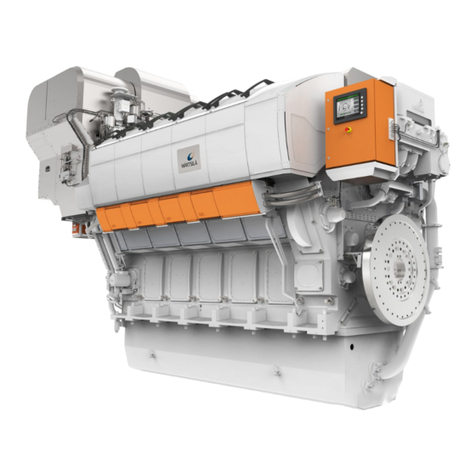
Wartsila
Wartsila ?31DF Series Product guide

Fiamma
Fiamma 98655Z111 Installation and usage instructions
