Trusted Clean SELLEYS S33 User manual
OPERATING MANUAL
SELLEYS S33 AIRLESS SPRAYPACK

OPERATING MANUAL – SELLEYS S33
2
CONTENTS
1. SAFETY INFORMATION
1.1 General Safety Precautions
1.2 Specific Safety Hazards and Precautions
1.3 Earthing Instructions
2. COATINGS
2.1 Suitable Coatings
2.2 Preparation of Coating Materials
2.3 Viscosity
2.4 2-component Coating Materials
2.5 Coatings Containing Abrasive Materials
3. EQUIPMENT
3.1 Technical Data
3.2 Main Components
3.3 Component Identification
4. OPERATING INSTRUCTIONS
4.1 Setup
4.2 Startup
4.3 Pressure Relief Procedure
4.4 Installation of Spray Tip
4.5 Clearing Spray Tip Clogs
4.6 Before Spraying the Coating Material
4.7 Method of Spraying
4.8 Handling the High-Pressure Hose
4.9 In Case of Interrupted Operation
5. CLEANING AND MAINTENANCE
5.1 Cleaning and Shutting Down
5.2 Cleaning the Airless Spray Gun
5.3 Disassembly of the Gun Filter
5.4 Assembly of the Gun Filter
6. MALFUNCTIONS
7. SERVICING AND REPAIRS
7.1 Routine Checking
7.2 Repairs to the Packings
8. CONNECTION GUIDE
9. PARTS AND ASSEMBLY

OPERATING MANUAL – SELLEYS S33
3
WARNING
This unit is capable of extremely high spraying pressures that can cause serious and/or minor
injury by injection and extensive damage to property.
IMPORTANT
All replacement parts and accessories should ONLY be purchased from SELLEYS or an
authorised distributor of SELLEYS equipment. Servicing should ONLY be carried out by SELLEYS
or an authorised distributor of SELLEYS equipment. If these conditions are not met, the operator
assumes all liability for injury and property damage arising from the use of this unit.
1. SAFETY INFORMATION
Please read the following important information carefully.
The following symbols indicate specific types of safety hazards.
Indicates a potential hazard that may cause serious injury to the operator or
loss of life.
Indicates a potential hazard that may cause minor injury to the operator or
to the equipment.
Indicates important information.

OPERATING MANUAL – SELLEYS S33
4
1.1 GENERAL SAFETY PRECAUTIONS
NEVER
• use the spray gun without the safety guard in place
• operate faulty units or use faulty accessories
• attempt to repair a damaged hose
• leave this equipment unattended
• move the unit when it is running
• spray outside on windy days
ALWAYS
• ensure that this unit is properly earthed
• ensure that the power cord, air hose and spray hoses are optimally routed to minimise slip, trip and fall hazards
• immediately and thoroughly clean up all material and solvent spills to prevent slip hazards
• follow the material manufacturer’s instructions for safe handling of coating materials
• unplug the cord from the outlet before cleaning, maintaining or repairing this unit
• keep the power cord plug in sight during use to prevent accidental shutdowns and startups
• wear ear protection to protect against possible hearing loss from the noise produced by this unit, which can exceed 85 dB(A)
• keep this unit out of reach of children, unqualified adults and animals
• comply with local codes regarding ventilation, fire prevention, and operation
1.2 SPECIFIC SAFETY HAZARDS AND PRECAUTIONS
SAFETY PRECAUTIONS TO PREVENT INJECTION INJURY
WARNING
Serious risk of injection injury. This equipment produces a high-pressure stream that can pierce the skin and subcutaneous
tissues, resulting in severe injury and even possible amputation.
IMPORTANT
The maximum operating range of the unit is 21 bar (22.1 MPa, 3200 PSI) fluid pressure.
NEVER
• put your fingers, hands or any other parts of your body into the spray jet
• point the spray gun at yourself or anyone else (including animals)
• allow the fluid stream to come into contact with any part of your body
• allow any leak in the fluid hose to come into contact with any part of your body
• put your hand in front of the gun
NOTE: Gloves do not provide full protection against injection injury.
• use a spray gun without both a working trigger lock and trigger guard in place
ALWAYS
• ensure that the gun trigger is locked, the fluid pump is shut o, and all pressure is released before servicing, cleaning the tip
guard, changing tips, or leaving the unit unattended
NOTE: Turning o the engine will not release the pressure. The PRIME/SPRAY valve or pressure bleed valve must be turned to their appropriate
positions to relieve system pressure.
• ensure that the tip guard remains in place during spraying
• remove the spray tip before flushing or cleaning the system
• carefully check the paint hose for leaks before each use, as even small leaks can cause injection injury
• ensure that all accessories, including but not limited to spray tips, guns, extensions and hose, are rated at or above the
maximum operating pressure range of the sprayer
IMPORTANT MEDICAL INFORMATION
Injection injury is a traumatic injury that requires immediate medical attention. Any laceration of the skin, no matter how minor
it seems, should not be treated as a simple cut. Fully inform the medical team about the coatings or solvents involved, as some
coatings are toxic when injected directly into the bloodstream. For serious injuries, a plastic surgeon or reconstructive hand
surgeon should be consulted.

OPERATING MANUAL – SELLEYS S33
5
SAFETY PRECAUTIONS TO PREVENT EXPLOSIONS AND FIRE
WARNING
This equipment produces a high-pressure stream that can pierce the skin and subcutaneous tissues, resulting in severe injury
and even possible amputation.
NEVER
• use plastic drop cloths or enclose the spray area with plastic sheets, as plastic can cause static sparks
• smoke in the spray area
• use any materials with a flashpoint lower than 21°C (70°F)
NOTE: Flashpoint is the temperature at which a fluid can produce sucient vapours to ignite.
ALWAYS
• ensure that the spray area is well-ventilated to prevent the build-up of flammable vapours
• avoid all ignition sources such as static electricity sparks, electrical appliances, flames, pilot lights, hot objects, and sparks from
connecting and disconnecting power cords and/or working light switches
• flush the unit into a separate metal container, at the lowest possible pump pressure and with the spray tip removed
• hold the gun firmly against the side of the container to prevent static sparks
• have a fire extinguisher nearby
• place the sprayer at a minimum of 6.1 metres (20 feet) from the surface to be sprayed, extending the hose if necessary. Since
flammable vapours are often heavier than air, the floor area must be well ventilated. The pump contains arcing parts that emit
sparks, which can ignite vapours.
• ensure that the equipment and objects in and around the spray area are properly grounded to prevent static sparks
• ensure that you are using a conductive or earthed high pressure hose
• ensure that the gun is earthed through the hose connection
• ensure that the power cord is connected to a grounded circuit
• ensure that the unit is connected to an earthed object such as a water pipe, steel beam, or other electrically earthed surface, via
the green earthing wire
• strictly follow the material and solvent manufacturer’s warnings and instructions, and read the coating material’s MSDS
(Material Safety Data Sheet) and technical information before use
SAFETY PRECAUTIONS TO PREVENT EXPLOSIONS DUE TO INCOMPATIBLE MATERIALS
WARNING
Serious risk of explosions due to incompatible materials. Accidental explosions due to incompatible materials can cause serious
injury and/or extensive damage to property.
NEVER
• use materials that contain bleach or chlorine
• use halogenated hydrocarbon solvents such as methylene chloride and 1,1,1-trichloroethane
NOTE: These substances are not compatible with aluminium and may cause an explosion. If you are in any doubt over a material’s compatibility
with aluminium, check with your coating supplier.
SAFETY PRECAUTIONS TO PREVENT HARM FROM TOXIC VAPOURS
WARNING
Vapours from paints, solvents, insecticides, and other materials can be harmful in the event of inhalation or contact with any part
of the body. Symptoms include severe nausea, fainting and poisoning.
ALWAYS
• use a respirator or mask
• wear protective eyewear
• wear protective clothing
OPERATING MANUAL – SELLEYS S33
6
SAFETY PRECAUTIONS TO PREVENT HARM FROM MOVING PARTS
WARNING
Moving parts can pinch, cut or amputate fingers and other body parts. Furthermore, equipment can start without warning.
ALWAYS
• keep clear of moving parts
• follow the Pressure Relief Procedure and disconnect all power sources before checking, moving or servicing the equipment
NEVER
• operate equipment with protective guards or covers removed
1.3 EARTHING INSTRUCTIONS
NEVER
• operate this unit unless you are sure that it has been properly earthed
• modify the earthing plug
• use a 3-to-2 adapter with this equipment
ALWAYS
• ensure that the earthing plug is plugged into an outlet that has been properly installed and earthed in accordance with local codes
• seek the advice of a qualified electrician if you need a new outlet installed to fit the earthing plug, do not fully understand these
earthing instructions, or are unsure as to whether this unit is properly earthed
• if required, use only a 3-wire extension cord with a grounding plug and a grounding receptacle that accepts the plug on this
equipment, and a minimum AWG (2.5mm2) to carry the current that this equipment draws
Conductor Size Length
AWG (American Wire Gauge) Metric Maximum
122.5mm215m (50 ft)
WARNING
Incorrect installation of the earthing plug can result in electric shock. If you need to repair or replace the cord or plug, do not
connect the green earthing wire to either blade terminal.
IMPORTANT
The wire with insulation, which has a green outer surface with or without yellow stripes, is the earthing wire. It must be
connected to the earthing pin.
Use of an undersized cord causes a drop in line voltage, loss of power and overheating.
A list of the materials used in the construction of this unit is available upon request for the purpose of determining compatibility
with coating materials.
2. COATINGS
Please read the following important information carefully.
2.1 SUITABLE COATINGS
This unit is suitable for the application of:
• dilutable lacquers and paints
• coatings containing solvents
Do not spray coatings other than those listed above without the prior approval of SELLEYS or the authorised distributor of this unit.
• 2-component coating materials
• dispersions
• latex paints

OPERATING MANUAL – SELLEYS S33
7
2.3 VISCOSITY
This unit is able to process highly viscous coating materials of up to around 20,000 mPa-s.
Highly viscous coating materials can be diluted according to the manufacturer’s instructions.
When preparing two-component coating materials for spraying, follow the manufacturer’s instructions and do not skimp on the
mixing/processing time. While the components are processing, thoroughly rinse and clean the unit with suitable cleaning agents.
Coatings that contain sharp-edged aggregates and additional materials cause intense wear and tear on this unit’s parts, including
its valves, high-pressure hose, spray gun and tip.
Use of abrasive coatings may shorten the working life of this unit.
2.4 2-COMPONENT COATING MATERIALS
2.5 COATINGS CONTAINING ABRASIVE MATERIALS
Always filter and stir the coating material before application. To prevent downtime, make sure that no air bubbles are introduced,
especially when stirring the coating material with motor-driven agitators.
2.2 PREPARATION OF COATING MATERIALS
3. EQUIPMENT
Please read the following important information carefully.
3.1 TECHNICAL DATA
Dimension (L x W x H) 680 x 640 x 900mm
Weight 62kg
Motor output 3.3kW
Flow rate (with water) 4.5l/min
Max. tip size 0.033”
Max. operating pressure 220 bar
Voltage 220 – 240V, 50 – 60Hz
Max. temperature of coating material 43°C
Max. viscosity 25,000 mPa-s
Max. sound pressure level 80dB
High pressure hose DH 6mm, 15m
OPERATING MANUAL – SELLEYS S33
8
160 110 58 72
126
86
36
90
6
83
12
14
51
71
175
108
95
77
55
31
94
85
24
104
103
30
89
152
76
19
17
16
166
166
48
87
93
44
43
56
117
28
10
22
11
8
171
62
37
124
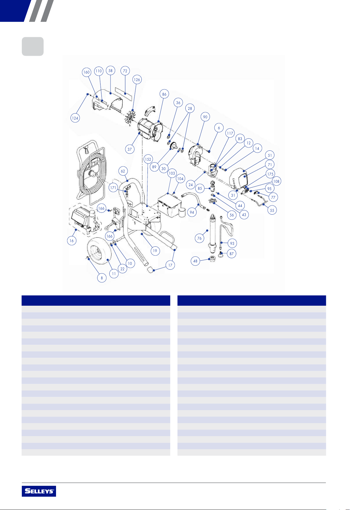
3.2 MAIN COMPONENTS
NO. NAME QUANTITY
6 SHCS 5
8 Protection clip 2
10 Spacer ring 2
11 Pneumatic tyre 2
12 Washer 4
14 Screw cap 4
16 DESC-Control assembly 1
17 Trolley frame cap 2
19 Hex nuts, flange head 8
22 Washer, wave spring 2
24 Locking nut 2
28 Spacer ring 2
30 Spacer ring 1
31 SHCS 4
36 Spacer ring 1
37 Hex nut 4
43 Fixed spring 1
44 Pin 1
48 Suction filter 1
51 Front cover 1
55 Shelf 1
56 Fixed nut 1
58 Rear cover 1
NO. NAME QUANTITY
62 Trolley frame 1
76 Suction tube 1
77 Drain line 1
83 Bearing housing 1
84 Motor 1
85 Connecting rod 1
87 Thread deflector 1
89 Gear combination 1
90 Drive housing 1
90a Spacer ring 1
93 Return hose 1
94 Fluid outlet 1
95 SHCS 1
103 Toolbox 1
104 SHCS 1
107 SHCS 4
108 Oil reservoir 1
124 Screw 2
126 Fan 1
152 Frame assembly 1
166 SCHS 2
171 Seal 2
175 Spacer ring 1

OPERATING MANUAL – SELLEYS S33
9
3.3 COMPONENT IDENTIFICATION
1 DESC-Control display
2 ON/OFF switch
3 Pressure control knob
4 Relief valve
5 Gun trigger lock
6 Return hose
7 Suction tube
2
1
2
3
4
7
6
5
OPERATING MANUAL – SELLEYS S33
10
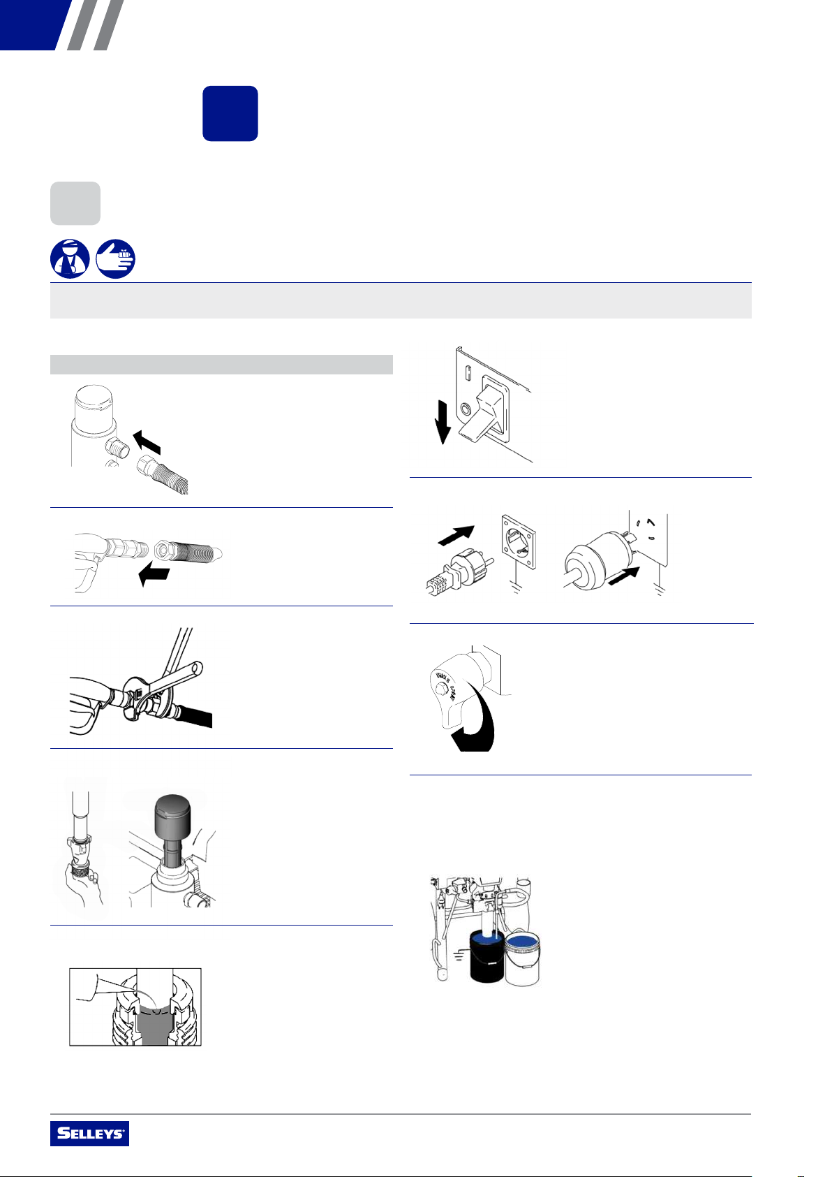
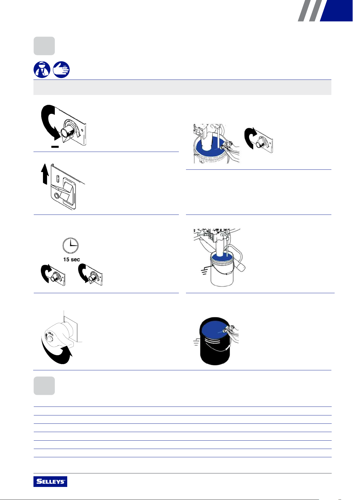
9. Place suction tube into a metal pail partially filled with
residual water. Attach ground wire to pail and to true earth
ground (see Earthing Instructions). Perform steps 1 – 5
of Startup to flush out storage oil shipped in sprayer. Use
water to flush water-based paint and appropriate solvent to
flush oil-based paint and storage oil.
4.1 SETUP
WARNING
Serious risk of explosions due to incompatible materials. Accidental explosions due to incompatible materials can cause serious
injury and/or extensive damage to property.
4. OPERATING INSTRUCTIONS
Please read the following important information carefully.
1. Connect 15m (50 ft) airless hose to sprayer and tighten
securely
NOTE: Remove adapter fitting for 13mm (1/2 in.) hose.
5. Fill throat packing nuts with separating oil to prevent
premature packing wear. Do this each time you spray.
2. Install airless hose to the fluid inlet of the spray gun
3. Tighten securely
6. Turn power OFF
8. Turn the relief valve to "PRIME" position
7. Plug power supply cord into a properly grounded electrical
outlet
4. Remove inlet strainer and suction filter when spraying
plaster materials
OPERATING MANUAL – SELLEYS S33
11
4.3 PRESSURE RELIEF PROCEDURE
4.2 STARTUP
WARNING
Serious risk of explosions due to incompatible materials. Accidental explosions due to incompatible materials can cause serious
injury and/or extensive damage to property.
1. Turn pressure control knob to "minimum" 5. Trigger the spray gun, whilst increasing the pressure
control knob, if necessary
6. Inspect for leaks. If leaks occur, perform Pressure Relief
Procedure. Tighten fittings. Perform Startup steps 1 - 5. If
no leaks, proceed to step 6.
7. Place suction tube into the container of material
8. Trigger gun again into flushing pail until paint appears.
Move gun to paint pail and trigger for 20 seconds. Set gun
safety ON. Assemble tip and guard.
2. Turn power ON
3. Increase pressure to start motor and allow fluid to
circulate through return hose for 15 seconds. Decrease
pressure control knob to minimum.
4. Turn relief valve to "SPRAY" position
Follow these steps carefully.
1. Immerse the suction tube and return hose in a container, filled with a suitable cleaning agent
2. Turn the pressure control knob counter-clockwise to minimum pressure
3. Turn the relief valve and set to "PRIME" position
4. Wait until the cleaning agent discharges from the return hose
5. Turn the relief valve and set to "SPRAY" position
6. Pull the trigger of the spray gun
7. Spray the cleaning agent from the unit into a container
OPERATING MANUAL – SELLEYS S33
12
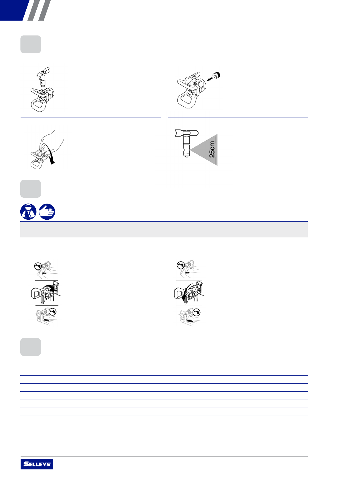
3. Install assembled spray tip and nozzle holder in spray gun 4. Install appropriate spray tip for your material
1. Release trigger, put safety ON. Rotate Spray Tip. Take
safety OFF. Trigger gun to clear clog. Never point gun at
your hand or into a rag!
2. Put safety ON. Return Spray Tip to original position. Take
safety OFF and continue spraying.
11
4.3
1. Insert tip cylinder into guard (arrow points forward).
2. Install Nozzle Seal (curved side in) into housing.
3. Install assembled tip and guard onto spray gun.
4. Install appropriate tip for your material.
4.4 Clear pray Tip Clogs
1. Release trigger, put safety ON. Rotate Spray Tip.
Take safety OFF. Trigger gun to clear clog. Never
point gun at your hand
or into a rag!
2. Put safety ON. Return Spray Tip to original position.
Take safety OFF and continue spraying.
4.6 BEFORE SPRAYING THE COATING MATERIAL
Follow these steps carefully.
1. Turn the pressure control knob counter-clockwise to minimum pressure
2. Turn the relief valve and set to "PRIME" position
3. Switch the unit ON
4. Wait until the coating material discharges from the return hose
5. Turn the relief valve and set to "SPRAY" position
6. Trigger the spray gun and spray into a container until the coating material exits the spray gun continuously
7. Increase the pressure by slowly turning the pressure control knob clockwise
8. Check the spray pattern and increase the pressure until the desired atomisation is attained
9. The unit is ready to spray
1. Insert spray tip into nozzle holder (arrow points forward) 2. Insert nozzle seal (curved side in) into housing
4.5 CLEARING SPRAY TIP CLOGS
WARNING
Serious risk of explosions due to incompatible materials. Accidental explosions due to incompatible materials can cause serious
injury and/or extensive damage to property.
4.4 INSTALLATION OF SPRAY TIP
OPERATING MANUAL – SELLEYS S33
13
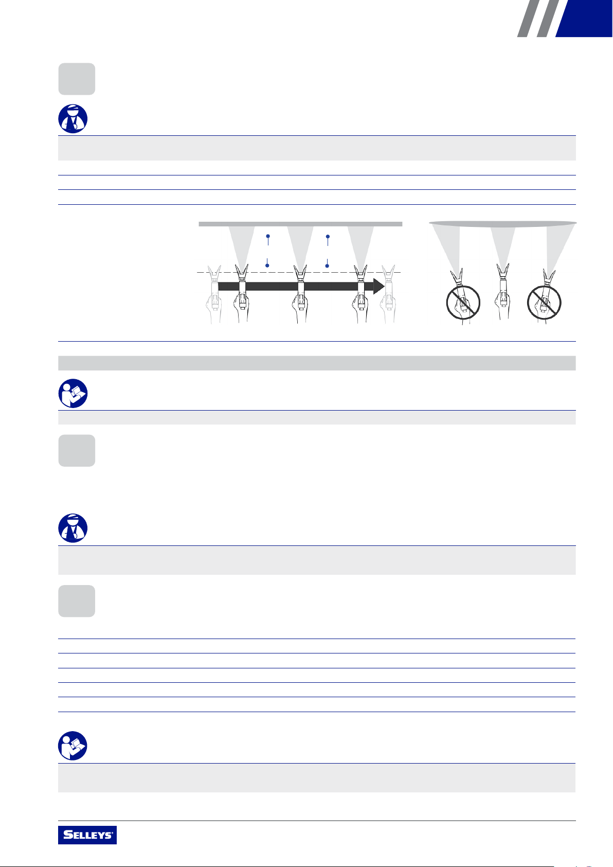
3. To ensure even application:
• keep your arm moving
at a constant speed
• keep the spray gun
perpendicular to the
surface
• keep the spray gun at
a constant distance
of 25 to 30cm from
the surface
• overlap each stroke
by about 30%
4. Release the gun BEFORE ending the stroke
NOTE: Gloves do not provide full protection against injection injury.
IMPORTANT
If very sharp edges or streaks appear on the coated surface, increase the operating pressure or dilute the coating material.
4.8 HANDLING THE HIGH-PRESSURE HOSE
Avoid sharp bending or kinking of the high-pressure hose. The smallest bending radius amounts to about 20cm.
Do not drive over the high-pressure hose, and avoid contact with sharp objects and edges.
WARNING
Defective high-pressure hoses can leak and cause serious injection injury. Replace defective high-pressure hoses immediately.
Never attempt to repair a defective high-pressure hose.
4.9 IN CASE OF INTERRUPTED OPERATION
Follow these steps carefully.
1. Turn the relief valve and set to "PRIME" position
2. Switch the unit OFF
3. Turn the pressure control knob counter-clockwise to minimum pressure
4. Pull the trigger of the spray gun in order to release the pressure from the high-pressure hose and spray gun
5. Secure the spray gun
6. Leave the suction tube (or the suction hose and return hose) immersed in the coating material, or in a cleaning agent
IMPORTANT
If a fast-drying or two-component coating material is used, ensure that the unit is rinsed with a suitable cleaning agent within the
processing time.
25 – 30cm 25 – 30cm
4.7 METHOD OF SPRAYING
WARNING
Never trigger the gun unless the tip is completely turned to either the spray or the unclog position. Always engage the gun trigger
lock before removing, replacing or cleaning the spray tip.
Follow these steps carefully.
1. Ensure that the nozzle holder guard is in place
2. Trigger the gun AFTER starting the stroke
25 – 30cm 25 – 30cm

OPERATING MANUAL – SELLEYS S33
14
5. CLEANING AND MAINTENANCE
Please read the following important information carefully.
A. Turn power OFF. Wait 30 seconds for power to dissipate. 1. Do Steps A – D first. Remove suction tube from paint and
place in flushing fluid.
C. Turn the pressure control knob to minimum, and trigger
the gun to release pressure
B. Lock gun trigger safety. Remove nozzle holder and spray tip. 2. Unscrew the filter cap, and clean the strainer filter
D. Put the return the return hose in a container and turn the
relief valve to "PRIME" position
3. Switch power ON, and turn the relief valve to "SPRAY" position
NOTE: Use water for water-based material and appropriate solvent
for oil-based material.
4. Increase pressure slowly. Hold gun against the paint
container. Unlock the trigger, and flush the gun until the
flushing fluid appears.
5.1 CLEANING AND SHUTTING DOWN
WARNING
Serious risk of explosions due to incompatible materials. Accidental explosions due to incompatible materials can cause serious
injury and/or extensive damage to property.

OPERATING MANUAL – SELLEYS S33
15
5. Move gun to waste pail, hold gun against pail, trigger gun
to thoroughly flush system. Release trigger and put trigger
safety ON.
9. Turn the relief valve to "PRIME" position, and ensure the
pressure control knob is set to "minimum". Unplug the unit
from the power source.
6. Turn the relief valve to "PRIME" position and allow the
flushing fluid to circulate and clean the return hose 10. Remove filters from gun and sprayer, if installed. Clean
and inspect. Install filters.
7. Remove the suction tube and allow the unit to run and
drain the flushing fluid
11. If flushing with water, flush again with mineral spirits, or
a suitable product, to leave a protective coating to prevent
freezing or corrosion
8. Turn the relief valve to "SPRAY" position. Trigger the gun
into the flushing pail. Switch OFF power. 12. Wipe sprayer, hose and gun with a rag soaked in water or
mineral spirits
IMPORTANT
The container must be earthed in case of coating materials that contain solvents.
5.2 CLEANING THE AIRLESS SPRAY GUN
Follow these steps carefully.
1. Rinse the airless spray gun with a sucient amount of a suitable cleaning agent
2. Thoroughly clean the tip with a sucient amount of a suitable cleaning agent until all unused coating material has been removed
3. Thoroughly clean the outside of the airless spray gun
5.3 DISASSEMBLY OF THE GUN FILTER
Follow these steps carefully.
1. Pull the protective guard (Figure 1.1) forward with moderate force
2. Unscrew the grip (1.2) from the gun housing and remove the gun filter (1.3)
13
5. Move gun to waste pail, hold gun against pail,
trigger gun to thoroughly flush system. Release
trigger and put trigger safety ON.
6. Turn prime valve down and allow flushing fluid to cir-
culate for 15 seconds to clean drain tube.
7. Raise pump above flushing fluid and run sprayer for
15 to 30 seconds to drain fluid.
8. Close drain valve. Trigger gun into flushing pail to
purge fluid from hose. Turn power OFF.
9. Open prime valve. Unplug sprayer.
10. Remove filters from gun and sprayer, if installed.
Clean and inspect. Install filters.
11. If flushing with water, flush again with mineral spirits,
or Pump Armor, to leave a protective coating to pre-
vent freezing or corrosion.
12. Wipe sprayer, hose and gun with a rag soaked in
water or mineral spirits.

OPERATING MANUAL – SELLEYS S33
16
5.4 ASSEMBLY OF THE GUN FILTER
Follow these steps carefully.
1. Place the gun filter (Figure 1.3) with the long cone pointing up into the gun housing
2. Screw the grip (1.2) into the gun housing and tighten
3. Slot in the protective guard (1.1)
1
3
2
IMPORTANT
Replace the gun filter if it is clogged or faulty.
6. MALFUNCTIONS
Refer to the chart below for instructions on how to correct common malfunctions.
TYPE OF MALFUNCTION POSSIBLE CAUSES CORRECTIVE MEASURES
A. Unit does not start 1. No voltage applied
2. Pressure setting is too low
3. ON/OFF switch is defective
1. Check voltage supply
2. Turn up pressure control knob
3. Replace
B. Unit does not draw in material 1. Relief valve is set to SPRAY
2. Filter projects over the fluid level
and sucks air
3. Filter is clogged
4. Suction hose/suction tube is loose, i.e.,
the unit is sucking in outside air
1. Set relief valve to PRIME (circulation)
2. Refill the coating material
3. Clean or replace the filter
4. Clean connecting points. Replace
O-rings if necessary. Secure suction
hose with retaining clip
C. Unit draws in material, but the
pressure does not build up
1. Spray tip is heavily worn
2. Spray tip is too large
3. Pressure setting is too low
4. Filter is clogged
5. Coating material flows through the
return hose when the relief valve is
in the SPRAY position
6. Packings are sticky or worn
7. Valve balls are worn
8. Valve seats are worn
1. Replace
2. Select a smaller spray tip
3. Turn pressure control knob clockwise
to increase pressure
4. Clean or replace the filter
5. Remove and clean or replace
relief valve
6. Remove and clean or replace packings
7. Remove and replace valve balls
8. Remove and replace valve seats
D. Coating material exits at the
top of the fluid section
1. Upper Packing is worn
2. Piston is worn
3. Incorrect high-pressure hose type
1. Remove and replace packing
2. Remove and replace piston
3. Only use original high-pressure hoses
E. Increased pulsation at the
spray gun
1. Incorrect high-pressure hose type
2. Spray tip is worn or too large
3. Pressure is too high
1. Only use original-high pressure hoses
2. Replace spray tip
3. Turn pressure control knob to a lower
number
F. Poor spray pattern 1. Spray tip is too large for the coating
material being sprayed
2. Pressure setting incorrect
3. Volume is too low
4. Coating material viscosity
is too high
1. Replace spray tip
2. Turn pressure control knob until a
satisfactory spraying pattern is achieved
3. Clean or replace all filters
4. Thin out according to the manufacturer’s
instructions
G. Unit loses power 1. Pressure setting is too low 1. Turn pressure control knob clockwise to
increase
Figure 1

OPERATING MANUAL – SELLEYS S33
17
6. MALFUNCTIONS
102
7. SERVICING AND REPAIRS
Please read the following important information carefully.
Repairs to the Relief Valve, Inlet and Outlet Valve, and Packings should only be carried out by a qualified electrician or an authorised
distributor of SELLEYS equipment.
Remember to get this unit serviced annually (or more often in the case of heavy usage) by an authorised distributor of SELLEYS
equipment.
WARNING
Always unplug the power plug from the outlet before commencing any repair works on the unit.
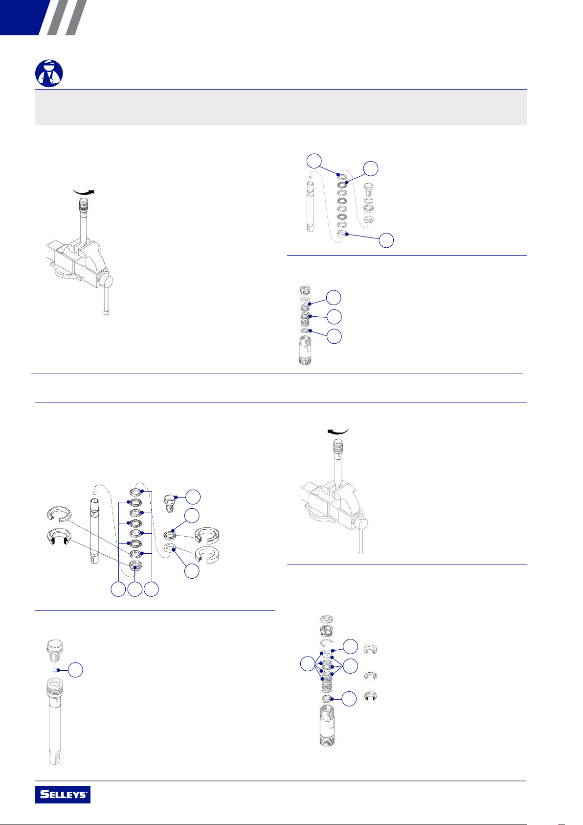
1. Remove packing nut (102)
3. Disassemble intake valve. Clean and inspect O-ring (122).
NOTE: A pick may be required to remove O-ring.
119
121
122
123
120
2. Unscrew intake valve from cylinder
5. Remove piston rod from sleeve, or remove sleeve from
cylinder. Remove O-ring from top of sleeve (or from inside
of cylinder if O-ring did not come out with sleeve).
4. Tap piston rod out of cylinder with a hammer or flip over
and tap piston rod out against a bench
NOTE: Sleeve may come out of cylinder with piston.
7.1 ROUTINE CHECKING
Prior to every use/on a weekly basis:
• check the high-pressure hoses and the device connecting the line and plug for damage and wear
• check the inlet valve, outlet valve and filter for damage and wear
• check the high-pressure hose for any notches or bulges, especially around the transitions in the fittings. You should
be able to easily turn the union nuts, without using force.
7.2 REPAIRS TO THE PACKINGS
To disassemble the pump, follow these steps carefully.
OPERATING MANUAL – SELLEYS S33
18
105
106
107
104
117
WARNING
Component rupture hazard. To reduce the risk of serious injury from pressurised fluid, do not clean or wipe the piston valve
threads. Cleaning the piston valve threads could destroy the special sealing patch and cause the piston valve to come loose
during operation.
6. Unscrew piston valve from piston rod. Clean and inspect
parts. The piston has a special thread locking/sealing
patch. Do not remove the patch. The patch allows four
disassembly/assembly procedures before it is necessary
to apply thread sealant to the threads.
1. Soak all leather packings in cleaning agent for 1 hour
minimum prior to assembly. Stack positioning sleeve
(112) on piston rod. Alternately stack (113) and (114)
(note orientation) on piston rod. Install lower gland (116).
Install backup U-cup (115) (note orientation) on steel
ball seat (118).
To assemble the pump, follow these steps carefully.
112 113114
118
115
116
2. Install small ball (117) in piston rod. If thread sealant is
applied, ensure none of the sealant gets onto the small ball.
8. Remove upper seals (105 & 106) and upper gland from
cylinder (107)
105
107
7. Remove lower seals (113 & 114) and lower gland (116)
from piston rod
3. Tighten piston valve to piston rod
4. Soak all leather seals in a cleaning agent for one hour.
Place upper gland (107) in cylinder. Alternately stack upper
leather seals (106) (note orientation). Place the positioning
sleeve (104) on top of the cylinder.
113
114
116
106

OPERATING MANUAL – SELLEYS S33
19
10. Install intake valve on cylinder. If a wrench is used, torque
as follows.
5. Install the guide sleeve (101) onto the packing nut (102),
and install the packing nut into the cylinder
6. Grease piston packings
NOTE: Do not slide piston assembly into top of sleeve as this may
damage piston packing.
7. Slide piston rod into the bottom of cylinder
8. Grease the piston rod
120
121
122
123
9. Assemble the O-ring (122), big ball seat (121) and
big ball (120), into the pump assembly (123)
102
101

OPERATING MANUAL – SELLEYS S33
20
11. Torque seal and packing nut (102) down 12. Then tighten packing nut down until leakage stops
or lessens
8. Grease top inch or two of piston rod that will go
through the cylinder throat packings.
9. Grease o-rings (11 1) and place on sleeve. Slide
sleeve/piston rod assembly into bottom of cylinder.
10.Reassemble intake valve with new o-ring (122),
seat (121 ) and ball (120 ). Seat may be flipped over
and used on other side. Clean seat thoroughly.
11. Install intake valve on cylinder. If a wrench is used
torque as follows:
12.Torque seal and packing nut (102) down.
13.Then tighten packing nut down until leakage stops
or lessens.
102
8. Grease top inch or two of piston rod that will go
through the cylinder throat packings.
9. Grease o-rings (11 1) and place on sleeve. Slide
sleeve/piston rod assembly into bottom of cylinder.
10.Reassemble intake valve with new o-ring (122),
seat (121 ) and ball (120 ). Seat may be flipped over
and used on other side. Clean seat thoroughly.
11. Install intake valve on cylinder. If a wrench is used
torque as follows:
12.Torque seal and packing nut (102) down.
13.Then tighten packing nut down until leakage stops
or lessens.
On/O
Black wire
Power plug
Black wire
Green wire
Potentiometer
Pressure sensor
Motor
White wire
8. CONNECTION GUIDE
9. PARTS AND ASSEMBLY
Please examine the following diagrams carefully.
102
Table of contents
Popular Paint Sprayer manuals by other brands

WAGNER
WAGNER W 500 Translation of the original operating instructions

Reanin
Reanin K2000 user manual

Avanti
Avanti 57641 Owner's manual & safety instructions

GUSMER
GUSMER GAP operating manual

Avanti
Avanti 64934 Owner's manual & safety instructions

C.A. Technologies
C.A. Technologies Cougar Product information


DÖRR
DÖRR EcoGun AA MAN 2 P operating manual

FAST AG Solutions
FAST AG Solutions Fast Sprayers 9500 Series Operator's manual

Nordson
Nordson Tribomatic 2 Customer product manual

Craftsman
Craftsman 24531 - Tow-Behind Sprayer owner's manual

Titan
Titan CAPSPRAY 75 owner's manual

DÖRR
DÖRR EcoGun AS AUTO pro HD Operation manual