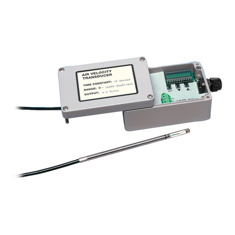
TSI Instruments ALNOR AVT 55 User manual

Air Velocity Transducers
AVT 55/65/75
Air Velocity Transducer

LIMITATION OF WARRANTY AND LIABILITY
Seller warrants that this product, under normal use and service as described in the
operator's manual, shall be free from defects in workmanship and material for a period
of twenty-four (24) months, or the length of time specified in operator's manual, from
the date of shipment to the customer. This limited warranty is subject to the following
exclusions:
a. Batteries and certain other components when indicated in specifications are
warranted for a period of 90 days from the date of shipment to the customer.
b. With respect to any repair services rendered, Seller warrants that the parts repaired
or replaced will be free from defects in workmanship and material, under normal use,
for a period of 90 days from the date of shipment to the customer.
c. Seller does not provide any warranty on finished goods manufactured by others.
Only the original manufacturer's warranty applies.
d. Unless specifically authorized in a separate writing by Seller, Seller makes no
warranty with respect to, and shall have no liability in connection with, any goods
which are incorporated into other products or equipment by the Buyer. All goods
returned under warranty shall be at the Buyer’s risk of loss, Seller’s factory prepaid,
and will be returned at Seller’s risk of loss, Buyer’s factory prepaid.
The foregoing is IN LIEU OF all other warranties and is subject to the conditions and
LIMITATIONS stated herein. NO OTHER EXPRESS OR IMPLIED WARRANTY OF
FITNESS FOR PARTICULAR PURPOSE OR MERCHANTABILITY IS MADE.
THE EXCLUSIVE REMEDY OF THE USER OR PURCHASER, AND THE LIMIT OF
THE LIABILITY OF SELLER FOR ANY AND ALL LOSSES, INJURIES, OR DAMAGES
IN CONNECTION WITH THIS PRODUCT (INCLUDING CLAIMS BASED ON
CONTRACT, NEGLIGENCE, STRICT LIABILITY, OTHER TORT, OR OTHERWISE)
SHALL BE THE RETURN OF THE PRODUCT TO THE FACTORY OR DESIGNATED
LOCATION AND THE REFUND OF THE PURCHASE PRICE, OR, AT THE OPTION
OF SELLER, THE REPAIR OR REPLACEMENT OF THE PRODUCT. IN NO EVENT
SHALL SELLER BE LIABLE FOR ANY SPECIAL, INCIDENTAL OR
CONSEQUENTIAL DAMAGES. SELLER SHALL NOT BE RESPONSIBLE FOR
INSTALLATION, DISMANTLING, REASSEMBLY OR REINSTALLATION COSTS OR
CHARGES. NO ACTION, REGARDLESS OF FORM, MAY BE BROUGHT AGAINST
THE SELLER MORE THAN ONE YEAR AFTER THE CAUSE OF ACTION HAS
ACCRUED.
The purchaser and all users are deemed to have accepted the terms of this
LIMITATION OF WARRANTY AND LIABILITY, which contains the complete and
exclusive limited warranty of Seller. This LIMITATION OF WARRANTY AND LIABILITY
may not be amended or modified nor may any of its terms be waived except by a
writing signed by an authorized representative of Seller
Service Policy
Knowing that inoperative or defective instruments are as detrimental to TSI as they are
to our customers, our service policy is designed to give prompt attention to any
problems. If any malfunction is discovered, please contact your nearest sales office or
representative, or call Customer Service department at (800) 874-2811 (USA) and (1)
651-490-2811 (International).

TABLE OF CONTENTS
Introduction........................................................................................1
Parts Identification.............................................................................1
Mounting the Transducer Electronics Enclosure...........................2
Mounting the Transducer Probe ......................................................3
Wiring the Transducer.......................................................................3
Setting Up the Transducer................................................................4
More Detail on the Time Constant....................................................5
More Detail on Span Adjustment .....................................................5
More Detail on Adjusting Output Signal at Zero Velocity..............5
Converting the Output Signal...........................................................6
Troubleshooting.................................................................................6
Cleaning the Sensor..........................................................................7
Calibration ..........................................................................................7
Specifications.....................................................................................8


1
Introduction
The Alnor®Air Velocity Transducer is a precision instrument designed to
measure air velocity in fixed installations or test applications. Alnor®
transducers indicate velocity at standard conditions of 70°F (21.1°C) and
14.7 psia (101.4 kPa). Each transducer must be setup in the field for the
desired velocity units, full scale velocity, output signal, and time constant.
Parts Identification
Carefully unpack the instrument and accessories. Check the parts against
Figure 1. If any are missing or damaged, notify your local distributor or TSI
immediately.
Figure 1
AVT 55/65/75
Manual
Probe mounting clips
#6 Sheet Metal Screws
#10 Sheet Metal Screws
Compression Fitting
Instruction Labels

2
5
4
2
1
6
3
7
Figure 2: Inside of Electronic Enclosure
1. Setup/Troubleshooting Display
5. Programming Instructions (foldout)
2. Push-Buttons (SET,
,
)
6. Compression Fitting (Power)
3. Terminal Block
7. Calibration Connector, factory use
4. Mounting Holes
only
Mounting the Transducer Electronics
Enclosure
The electronics enclosure should be mounted to a secure surface.
WARNING
Do not change the length of the transducer probe cable. Changing
the cable length will alter the performance and calibration of the
transducer.

3
Mounting the Transducer Probe
The probe should be securely mounted before use. If mounted in a duct or
pipe the probe should be at least 7.5 duct diameters downstream and 3 duct
diameters upstream of anything that could cause flow turbulence. The
orientation dot on the probe should face upstream.
Wiring the Transducer
Position the wires away from the SET - - push-buttons
Power Requirements: 11-30 VDC or 18-28 VAC 50/60 Hz,
350mA
Recommended Wire: 18 gauge shielded cable. To avoid electrical
interference, connect shield to ground on
transducer and ground or minus(-) terminal
on power supply.
Recommended Transformer: 24 VAC, 20VA. Each transducer should
have a separate AC transformer to avoid
shorting through the ground circuit.
Wiring for AC-Powered Operation

4
Wiring for DC-Powered Operation
Output Measuring
Device:
Use a fully differential input device (no ground
connection, plus (+) and minus (-) terminals are
independent), so the signal can float at the measuring
device. If fully differential input is not available,
current (mA) output should be selected.
Setting Up the Transducer
1. Turn the transducer power supply on. The instrument will go through a
pre-programmed power-up sequence. The internal display will sequence
through the current settings: Calibration date “CALdAtE”, “=“, month
and year “03.1995”(March 1995), measurement units “mEtErS”(m/s)
or “FEET”(fpm), “=“, selected output type and range “0-5V” and the
time constant “tc = 1.00” in seconds. The display will then show
velocity readings.
2. Push the SET button to enter setup mode. When setup mode is entered,
the transducer voltage/current output will drop below zero.
3. Use the and buttons to select the desired setting.
4. Use the SET button to advance to the next setup message.
Note: The output signal is disabled during the 15 second warm-up period
and when the transducer is in setup mode.
Setup Message
Available Settings
SELECt UnitS
FEEt (fpm) or mEtErS (m/s)
SELECt FULL
SCALE
Select full scale of the velocity range
SELECt OUtPUt
Select Output Type: 0-5V, 0-10V, 1-5V, 2-10V,
4-20mA, 0-20mA

5
Setup Message Available Settings
SELECt tc Select Time Constant: 0.05 to 10 seconds (see “More
Detail on the Time Constant”)
AdJUSt ZErO
Adjusts voltage/current output signal at zero velocity
(see “More Detail on Adjusting Output Signal at Zero
Velocity”)
AdJUSt SPAn Adjusts the voltage/current output by ±15% (see
”More Detail on Span Adjustment”)
More Detail on the Time Constant
In order to make a fluctuating display easier to read, the output time constant
can be set between 0.05 and 10 seconds. The time constant is actually an
averaging period. The output is the average of readings taken over the last
time-constant period. Readings are taken 20 times per time constant period
for a time constant greater than one second and 20 times per second for a
time constant of one second or less.
More Detail on Span Adjustment
A span factor can be entered to adjust the output signal up or down by
fifteen percent. While the span factor is shown on the display, the transducer
will measure velocity and output the appropriate voltage or current for that
velocity. (The time constant will not be active). By changing the span factor,
the transducer’s output signal can be adjusted up or down by up to 15%.
More Detail on Adjusting Output Signal at
Zero Velocity
In certain cases, the remote display will not read the same as the transducer
display output at zero velocity. To correct this discrepancy you will need to
adjust the output signal at zero velocity. Put the transducer into setup mode
and sequence through the setup messages until “AdJUSt ZErO” is shown
on the display. The transducer then displays and outputs the voltage or
current that has been set as the zero value. Adjust the transducer output
voltage or current using the and push-buttons. Adjust the output signal
until the remote device displays the expected zero. The transducer displays
the voltage or current that corresponds to the factory calibration. The
velocity readings should now be the same on both the setup/troubleshooting
display and the remote display.

6
Converting the Output Signal
In order to convert the transducer output signal into a velocity, use the
following equation:
V =
E - E
E - E * V
out 0
FS 0
FS
V = Measured Velocity
VFS = Full Scale Velocity Setting in fpm or m/s
Eout = Measured Output Voltage or Current Signal
Eo= Zero Flow Output Voltage or Current
EFS = Full Scale Voltage or Current Output
For example, if the actual output voltage is 2.6 volts for a transducer with
Full Scale Velocity = 50 m/s and output type = 1-5 Volts:
V =
.Volts - . Volts
.Volts - . Volts * m / s = m / s
26 10
50 10 50 20
Troubleshooting
Symptom Possible Problem & Solutions
No output or low output Incorrect input voltage
Sensor positioned incorrectly
Sensor not extended beyond protective shield
Wrong output type/range selected
Loose power or signal connections
Incorrect full scale velocity range selected
Displayed velocity is hard to
read Internal display is for setup/troubleshooting
only
Accuracy of velocity
reading suspect Dirty sensor, check for dirt or dust buildup.
Erratic readings Turbulent flow, check positioning of sensor,
increase time constant to dampen reading.

7
Cleaning the Sensor
Dust and dirt may build up on the sensor. If necessary, carefully clean the
sensor using a soft bristle brush dipped in a mild solvent like alcohol.
Calibration
To maintain a high degree of accuracy in your velocity measurements, TSI
recommends that you have your instrument calibrated annually. Please call
Customer Service for return instructions and a Return Material Authorization
(RMA) number.

8
Specifications
AVT- 55 AVT 65 AVT 75
Accuracy
±2.0% of
reading
1
±2.0% of
reading
1
±3.0% of
reading
2
±0.5% of full
scale of selected
range
±0.5% of
selected full
scale range
±1.0% of
selected full
scale range
Repeatability
<±1.0% of
reading
3
<±1.0% of
reading
3
NA
Response Time to Flow
0.2 sec4
0.2 sec4
5 sec4
Common specifications to all models
Field Selectable Velocity Ranges
AVT 55/65 25 fpm to 200, 250, 300, 400, 500, 750, 1000, 1250, 3000, 4000,
5000, 7500, 10000 fpm (0.125m/s to 1.0, 1.25, 1.50, 2.0, 2.5, 3.0,
4.0, 5.0, 7.5, 10.0, 12.5, 15.0, 20.0, 25.0, 30.0, 40.0, 50.0 m/s)
AVT 75 10 fpm to 100, 125, 150, 200, 250, 300, 400, 500 fpm
(0.05 m/s to 0.5, 0.75, 1.00, 1.25, 1.50, 2.0, 2.5 m/s)
Minimum Resolution...0.07% of selected full scale
Input Power..................11-30 VDC or 18-28 VAC, 350mA max5
Output Impedance.......Voltage mode: less than 1 ohm, 20 mA max source current
Output Resistance........Current mode: 500 ohms maximum load resistance
Output Signal (field selectable).......0-5V, 0-10V, 1-5V, 2-10V, 0-20mA, 4-20mA
Output Time Constant (field selectable)........... 0.05 to 10 seconds.
Probe Length................3 in, 6 in, 9 in or 12 in (7.5 cm, 15 cm, 21.5 cm or 30 cm)
Temperature Compensation Range: 32 to 140°F (0 to 60°C)
Sensor Operation: 32 to 200°F (0 to 93°C)
Electronics Operation: 32 to 200°F (0 to 93°C)
Storage: 32 to 200°F (0 to 93°C)
1from 64.4 to 82.4°F (18 to 28°C), outside this range add 0.11% per °F
(0.2% per °C), within temperature compensation range.
2from 68 to 78.8°F (20 to 26°C), outside this range add 0.28% per °F
(0.5% per °C), within temperature compensation range.
3Standard deviation based on one minute average from 100 to 1000 fpm
(0.5 to 5.0 m/s).
4For 63% of final value, tested at 1000 fpm (7.5 m/s).
5 Input voltage must be maintained within specifications at the transducer.
Calibration occurs with sensor oriented horizontally in a horizontal air flow.
Uncertainty increases in downward vertical flow at velocities less than 50 fpm
(0.25 m/s). Directional sensitivity of the AVT 75 is +5%/-20% of reading
+0/-10 fpm (+0/-0.05 m/s) over 270° solid angle regardless of flow direction.

LIMITES DE GARANTIE ET DE
RESPONSABILITÉ
Le vendeur garantit que, dans les conditions normales d’utilisation et d’entretien
décrites dans le manuel de l’utilisateur, ce produit sera exempt de tout défaut de
fabrication ou de matériel pour une durée de 24 (vingt-quatre) mois à compter de sa
date d’expédition au client. Cette garantie limitée fait l’objet des exclusions suivantes :
a. Les piles et certaines autres pièces composantes signalées dans les
caractéristiques techniques sont garanties pour une durée de 90 jours à compter
de la date d’expédition au client.
b. Concernant toute réparation, le vendeur garantit que, dans des conditions
normales d’utilisation, les pièces réparées ou remplacées seront exemptes de tout
défaut de fabrication ou de matériel pour une durée de 90 jours à compter de leur
date d’expédition au client.
c. Le vendeur n’offre aucune garantie sur des produits finis fabriqués par d’autres.
Seule la garantie du fabricant d’origine est valable.
d. Sauf cas d’autorisation écrite expresse du vendeur, le vendeur n’offre aucune
garantie et décline toute responsabilité en matière d’incorporation de tout bien
dans d’autres produits et équipement par l’acheteur. Tout produit renvoyé dans le
cadre de la garantie doit être expédié au vendeur en port payé, aux risques de
perte de l’acheteur, et sera réexpédié en port payé à l’acheteur aux risques de
perte du vendeur.
Cette garantie REMPLACE toute autre garantie et est soumise aux conditions et
LIMITES indiquées ici. LE VENDEUR N’OFFRE AUCUNE GARANTIE EXPLICITE OU
IMPLICITE QUANT À L’ADÉQUATION DU PRODUIT À UN USAGE PARTICULIER
OU À LA COMMERCIALISATION.
LE SEUL RECOURS DE L’UTILISATEUR OU DE L’ACHETEUR ET LA
RESPONSABILITÉ DU VENDEUR POUR TOUTE PERTE, DOMMAGE CORPOREL
OU MATÉRIEL EN RAPPORT AVEC CE PRODUIT (Y COMPRIS LES DEMANDES
SUR LA BASE D’UN CONTRAT, NÉGLIGENCES, RESPONSABILITÉ STRICTE OU
AUTRE TORT) SE LIMITENT AU RENVOI DU PRODUIT AU FABRICANT OU AU
DESTINATAIRE INDIQUÉ ET AU REMBOURSEMENT DU PRIX D’ACHAT OU, À
L’ENTIÈRE DISCRÉTION DU VENDEUR, À LA RÉPARATION OU AU
REMPLACEMENT DU PRODUIT. EN AUCUN CAS LE VENDEUR NE POURRA
ÊTRE TENU RESPONSABLE DE DOMMAGES SPÉCIAUX, ACCESSOIRES OU
INDIRECTS. LE VENDEUR N’EST PAS RESPONSABLE DES FRAIS
D’INSTALLATION, DE DÉMONTAGE, DE REMONTAGE OU DE RÉINSTALLATION
DU PRODUIT. LE VENDEUR NE POURRA FAIRE L’OBJET D’AUCUNE POURSUITE,
SOUS QUELQUE FORME QUE CE SOIT, SI UNE ANNÉE OU PLUS S’EST
ÉCOULÉE DEPUIS LA DATE DU MOTIF DE L’ACTION EN JUSTICE.
L’acheteur et tous les utilisateurs sont présumés avoir accepté les conditions des
présentes LIMITES DE GARANTIE ET DE RESPONSABILITÉ, qui contiennent la
garantie limitée complète et exclusive offerte par le vendeur. Ces LIMITES DE
GARANTIE ET DE RESPONSABILITÉ ne sauraient faire l’objet d’aucun amendement,
modification ou dérogation sans autorisation écrite signée par un représentant agréé
du vendeur.
Service après-vente
Attendu que des appareils défectueux portent autant préjudice à TSI qu’à nos clients,
notre service après-vente est conçu pour répondre rapidement à tout problème. En cas
de problème de fonctionnement, appeler le Service après-vente de TSI au (800) 874-
2811 (aux États-Unis) ou au (1) 651-490-2811 (international).

TABLE DES MATIÈRES
Introduction ........................................................................................1
Identification des Pièces...................................................................1
Montage du Boîtier Électronique du Transducteur........................2
Montage de la Sonde du Transducteur............................................3
Câblage du transducteur...................................................................3
Configuration du Transducteur........................................................4
Davantage de Détails sur la Constante de Temps..........................5
Davantage de Détails sur le Réglage d’Intervalle...........................5
Davantage de Détails Sur le Réglage du Signal de sortie à une
Vitesse Nulle.......................................................................................6
Conversion du Signal de Sortie........................................................6
Dépannage..........................................................................................7
Nettoyage de la Sonde.......................................................................7
Recalibration ......................................................................................7
Spécifications.....................................................................................8

1
Introduction
Le transducteur de vitesse aérodynamique Alnor est un instrument de
précision conçu pour mesurer la vitesse de l’air dans des installations fixes
ou des applications tests. Les transducteurs Alnor indiquent la vitesse dans
des conditions standard de 21,1°C (70°F) et 101,4 kPa (14,7 psia). Chaque
transducteur doit être configuré sur le terrain pour les unités de vitesse, la
déviation totale de la vitesse, le signal de sortie et la constante de temps
voulus.
Identification des Pièces
Déballer soigneusement l’instrument et les accessoires. Vérifier les pièces en
les comparant à la figure 1. En cas d’absence ou d’endommagement de
pièce, en avertir immédiatement le distributeur local ou TSI.
Figure 1
AVT 55/65/75
Manuel
Pinces de montage de la
sonde
Vis à tôle No. 6
Vis à tôle No.10
Raccord de compression
Etiquettes d’ instructions

2
5
4
2
1
6
3
7
Figure 2 : A l’intérieur du Boîtier Électronique
1. Affichage
configuration/dépannage 5. Instructions de programmation
(dépliant)
2. Boutons poussoirs
(SET,
,
)
6. Raccord de compression
(Alimentation)
3. Bloc terminal
7. Connecteur d’étalonnage,
4. Trous de montage
réservé à l’usine
Montage du Boîtier Électronique du
Transducteur
Le boîtier électronique doit être monté sur une surface solide.
AVERTISSEMENT
NE PAS modifier la longueur du câble de la sonde du transducteur.
Un tel changement modifie la performance et l’étalonnage du
transducteur.

3
Montage de la Sonde du Transducteur
La sonde doit être montée solidement avant toute utilisation. En cas de
montage dans une conduite ou dans un tuyau, la sonde doit se trouver à au
moins 7,5 diamètres de conduite en aval et à 3 diamètres de conduite en
amont de tout ce qui est susceptible de causer une turbulence de la
circulation de l’air. Le point d’orientation situé sur la sonde doit être dirigé
vers l’amont.
Câblage du transducteur
Eloigner les câbles des boutons poussoirs SET - -
Exigences électriques : 11-30 VCC ou 18-28 VAC 50/60 Hz,
350mA
Câble recommandé : blindé de calibre 18. Pour éviter toute
interférence électrique, connecter la gaine
de protection à la terre sur le transducteur et
la borne de terre ou négative (-) à la source
d’alimentation.
Transformateur recommandé : 24 VAC, 20VA. Chaque transducteur doit
être muni d’un transformateur AC séparé
pour éviter tout court-circuitage par le
circuit de mise à la terre.
Wiring for AC-Powered Operation

4
Wiring for DC-Powered Operation
Appareil de mesure
de sortie :
Utiliser un appareil d’entrée totalement différentiel
(pas de connexion à la terre, bornes positive (+) et
négative (-) indépendantes), afin que le signal puisse
flotter au niveau de l’appareil de mesure. En l’absence
d’une entrée totalement différentielle, choisir la sortie
courant (mA).
Configuration du Transducteur
1. Mettre en marche la source d’alimentation du transducteur.
L’instrument procède à une séquence de mise sous tension
préprogrammée. L’affichage interne défile à travers les réglages actuels
: Date de calibration “CaLdAtE”, “=“, mois et année “03.1995”(Mars
1995), unités de mesure “mEtErS”(m/s) ou “FEET”(pds/mn), “=“,
type et intervalle de sortie sélectionné “0-5V” et constante de temps “tc
= 1.00” en secondes. L’écran affiche ensuite les mesures de vitesse.
2. Appuyer sur le bouton SET pour entrer en mode de configuration. Une
fois dans ce mode, la tension/courant de sortie du transducteur tombe en
dessous de zéro.
3. Utiliser les boutons et pour sélectionner le réglage voulu.
4. Utiliser le bouton SET pour passer au message de configuration
suivant.
Remarque: Le signal de sortie est désactivé pendant la période de
préchauffage de 15 secondes et lorsque le transducteur se
trouve en mode de configuration.

5
Message de
Configuration
Paramètres Disponibles
SELECt UnitS FEEt (pds/mn) ou mEtErS (m/s)
SELECt FULL
SCALE Sélection de la déviation totale de l’intervalle de
vitesses
SELECt OUtPUt Sélection du type de sortie : 0-5V, 0-10V, 1-5V, 2-10V,
4-20mA, 0-20mA
SELECt tc Sélection de la constante de temps : 0,05 à 10 secondes
(voir Davantage de Détails sur la Constante de Temps)
AdJUSt ZErO Règle le signal de tension/intensité de sortie à la vitesse
zéro (voir Davantage de Détails Sur le Réglage du
Signal de sortie à une Vitesse Nulle)
AdJUSt SPAn Règle la tension/intensité de sortie par ±15% (voir
Davantage de Détails sur le Réglage d’Intervalle)
Davantage de Détails sur la Constante de
Temps
Afin de faciliter la lecture d’un affichage fluctuant, on peut régler la
constante de temps de sortie entre 0,05 et 10 secondes. La constante de
temps est en fait une période moyenne. La sortie correspond à la moyenne
des mesures prises au cours de la dernière période de constante de temps.
Les mesures ont lieu 20 fois par période de constante de temps supérieure à
une seconde et 20 fois par seconde pour une constante de temps égale ou
inférieure à une seconde.
Davantage de Détails sur le Réglage
d’Intervalle
On peut entrer un facteur d’intervalle pour régler le signal de sortie de
quinze pour cent vers le haut ou vers le bas. Alors que le facteur d’intervalle
est affiché à l’écran, le transducteur mesure la vitesse et produit la tension ou
l’intensité appropriée pour cette vitesse. (La constante de temps n’est pas
active.) La modification du facteur d’intervalle permet de régler le signal de
sortie du transducteur de quinze pour cent vers le haut ou vers le bas.

6
Davantage de Détails Sur le Réglage du Signal
de sortie à une Vitesse Nulle
Dans certains cas, il se peut qu’un affichage à distance ne corresponde pas à
la sortie du transducteur à vitesse nulle. Pour corriger cette différence, il est
nécessaire de régler le signal de sortie à vitesse nulle. Pour ce faire, mettre le
transducteur en mode de configuration et défiler à travers les messages de
configuration jusqu’à l’apparition de “AdJUSt ZErO” à l’écran. Le
transducteur affiche et émet alors la tension ou l’intensité réglée à la valeur
zéro. Régler la tension ou l’intensité de sortie du transducteur à l’aide des
boutons poussoirs et .Régler le signal de sortie jusqu’à ce que l’appareil à
distance affiche le zéro nécessaire. Le transducteur affiche la tension ou
l’intensité correspondant à la calibration en usine. Les mesures de vitesse
doivent désormais être identiques sur l’affichage de configuration/dépannage
et sur celui à distance.
Conversion du Signal de Sortie
Utiliser l’équation suivante pour convertir le signal de sortie du transducteur
en une vitesse :
V = E - E
E - E * V
out 0
FS 0
FS
V = Vitesse mesurée
VFS = Paramètre de déviation totale de vitesse en pds/mn ou m/s
Eout = Signal de tension ou intensité de sortie mesuré
Eo= Tension ou intensité de sortie à débit nul
EFS = Déviation totale de tension ou intensité
Par exemple, si la tension de sortie actuelle est de 2,6 volts pour un
transducteur avec vitesse maximum = 50 m/s et type de sortie = 1-5 Volts :
V =
.Volts - . Volts
.Volts - . Volts
* m / s = m / s
26 10
50 10
50 20
This manual suits for next models
2
Table of contents
Languages:
Other TSI Instruments Transducer manuals
Popular Transducer manuals by other brands

NK TECHNOLOGIES
NK TECHNOLOGIES AT-TH Series instructions

Omega
Omega OS641C-MV-LS product manual

Omega
Omega RH62 Series manual

Endress+Hauser
Endress+Hauser Cerabar T PMP 13 technical information

S+S Regeltechnik
S+S Regeltechnik Aerasgard KCO2-W Operation instructions

Thyracont
Thyracont VSR53D operating instructions