TST B410PT User manual

User Manual B410PT
Revision History
B410 PT Blade Chassis Installation Instruction
Rev Date Modications Update By
1.0 09/21/2006 First Draft Sio Fu
2.0 04/03/2007 (1) Add Reset Switch on LED board 16-0123-01A, section 2.1
(2) Change top cover to allow easy HDD installation section 3.2
(3) Add air-recirculation block off form section 3.3
(4) Add additional 2.5” slim HDD section 3.4
Sio Fu
3.0 4/18/2008 (1) Change push button for x the push button to hard to push issue
(2) Support Two 2.5” slim HDD
(3) Damper to reduce vibration to the HDD
(4) Plastic damper housing to reduce vibration to the Fan
(5) Support PCI-express MXM video
Sio Fu

User Manual B410PT
TST Corporation Blade Server Chassis
www.tstcom.com
User Guide
Revision 2.0 US version
April 2007

User Manual B410PT
Disclaimers
Information in this document is provided in connection with TST products. No li-
cense, express or implied, by estoppel or otherwise, to any intellectual property
rights is granted by this document. Except as provide in TST‘s Terms and Conditions
of Sale for such products, TST assumes no liability whatsoever, and TST disclaims
any express or implied warranty, relating to sale and/or use of TST products includ-
ing liability or warranties relating to tness for a particular purpose, merchantability,
or infringement of any patent, copyright or other intellectual property right. TST may
make changes to specications and product description at any time, without notice.
Designers must not reply on the absence or characteristics of any features or in-
structions marked “reserved” or “undened”. TST reserves these for future denition
and shall have no responsibility whatsoever for conicts or incompatibilities arising
from future changes to them.
The TST blade chassis may contain design defects or errors known as errata which
may causes the product to deviate from published specications. Current character-
ized errata are available on TST website. Visit www.tstcom.com
This document and function described in it is furnished under license and may only
be used or copied in accordance with the terms of the license. The information in this
manual is furnished for informational use only, is subject to change without notice,
and should not be construed as a commitment by TST. TST assumes no responsibil-
ity or liability for any errors or inaccuracies that may appear in this document that
may be provided in association with this document.
Except as permitted by such license, no part of this document may be reproduced,
stored in a retrieval system, or transmitted in any form or by any means without the
express written consent of TST.
Other brands and names may be claimed as the property of others
Copyright Terabytes Server Storage Tech Corp 2006
i

User Manual B410PT
ii iii
Limited Warranty
TST warrants to the original purchaser that the B410 blade enclosure product, includ-
ing the components therein, shall be free from defects in material and craftsmanship
for a limited period of three (3) years from the date of invoice. These are the only war-
ranties TST offers. TST makes no other warranties of any kind, express or implied,
written, oral or statutory, and expressly disclaims any implied warranties, including
merchantability or tness for any specic purpose, or freedom from patent infringe-
ment, regardless of origin, under no circumstance is TST liable for incidental or con-
sequential damages.
Under normal use, should the product under warranty fail in material or craftsman-
ship, TST will, at its sole discretion
(1)
(2)
Products that have been damaged through negligence, accident or misue of the
purchaser or its agents will be, at purchaser’s discretion, replaced at purchaser’s
expense or returned un-repaired, freight collect.
replace the product, freight perpaid, and honor the balance of the warranty
period
repair and return the product, freight prepaid and honor the balance of the
warranty period or

User Manual B410PT
Do not spill food or liquids on your system components, and never operate the
product in a wet environment.
WARNING: A WARNING indicates a potentially hazardous situation which, if not
avoided, could result in death or serious bodily injury.
CAUTION: A CAUTION indicates a potentially hazardous situation which, if not
avoided, may result in minor or moderate injury.
Safety Instructions
Use the following safety guidelines to ensure your own personal safety and to help protect your
server, storage system, or appliance from potential damage.
Throughout this guide, blocks of text may be accompanied by an icon and printed in bold type.
These blocks are notes, cautions, and warnings, and they are used as follows:
NOTE: A NOTE indicates important information that helps you make better use of your
system.
Read the installation instructions before connecting the system to the power
source
This unit is intended for installation in restricted access areas. A restricted
access area can be accessed only through the use of a special tool, lock and
key, or other means of security.
Do not work on the system or connect or disconnect cables during periods of
lightning activity
Only trained and qualied personnel should be allowed to install, replace, or
service this equipment
This equipment must be grounded. Never defeat the ground conductor or
operate the equipment in the absence of a suitably installed ground conductor.
Contact the appropriate electrical inspection authority or an electrician if you
are uncertain that suitable grounding is available.
Use only approved power cable(s). If you have not been provided with a power
cable for your server, storage system, or appliance, or for any AC-powered
option intended for your system, purchase a power cable that is approved for
use in your country. The power cable must be rated for the product and for the
voltage and current marked on the product’s electrical ratings label. The volt-
age and current rating of the cable should be greater than the ratings marked
on the product.
ii iii

User Manual B410PT
iv v
Keep your system components away from radiators and heat sources. Also, do
not block cooling vents.
Do not push any objects into the openings of your system components. Doing
so can cause re or electric shock by shorting out interior components.
Allow the product to cool before removing covers or touching internal
components.
Safety Instructions
If any of the following conditions occur, unplug the product from the electrical
outlet and replace the part or contact your authorized service provider:
The system cable, extension cable, or plug is damaged.
An object has fallen into the product.
The product has been exposed to water.
The product has been dropped or damaged.
To prevent bodily injury when mounting or servicing this unit in a rack, you
must take special precautions to ensure that the system remains stable. The
following guidelines are provided to ensure your safety:
This unit should be mounted at the bottom of the rack if it is the only unit in
the rack.
When mounting this unit in a partially lled rack, load the rack from the
bottom to the top with the heaviest component at the bottom of the rack
If the rack is provided with stabilizing devices, install the stabilizers before
mounting or servicing the unit in the rack.
Use caution when pressing the component rail release latches and sliding a
component into or out of a rack; the slide rails can pinch your ngers.
Do not overload the AC supply branch circuit that provides power to the rack.
The total rack load should not exceed 80 percent of the branch circuit rating.
Position system cables and power cables carefully; route system cables and
the power cable and plug so that they cannot be stepped on or tripped over.
Be sure that nothing rests on your system components’ cables or power cable.
Cleaning: Unplug your system from wall outlet before cleaning. Do not use
liquid or aerosol cleaners. Use a damp (not wet) cloth for cleaning.

User Manual B410PT
Safety Instructions
Ground yourself by touching an unpainted metal surface on the chassis, such as
the metal around the card-slot openings at the back of the computer, before touch-
ing anything inside your computer.
While you work, periodically touch an unpainted metal surface on the computer
chassis to dissipate any static electricity that might harm internal components.
When unpacking a static-sensitive component from its shipping carton, do not
remove the component from the antistatic packing material until you are ready to
install the component in your computer. Just before unwrapping the antistatic pack-
aging, be sure to discharge static electricity from your body.
To help protect your system/components from sudden, transient increases and
decreases in electrical power, use a surge suppressor, line conditioner, or uninter-
ruptible power supply (UPS).
To help avoid possible damage to the system board, wait 5 seconds after turning off
the computer before disconnecting a device from the computer.
When transporting a sensitive component, rst place it in an antistatic container or
packaging.
When you disconnect a cable, pull on its connector or on its strain-relief loop, not
on the cable itself. Some cables have a connector with locking tabs; if you are dis-
connecting this type of cable, press in on the locking tabs before disconnecting the
cable. As you pull connectors apart, keep them evenly aligned to avoid bending any
connector pins. Also, before you connect a cable, ensure that both connectors are
correctly oriented and aligned.
Handle components and cards with care. Do not touch the components or contacts
on a card. Hold a card by its edges or by its metal mounting bracket. Hold a compo-
nent such as a microprocessor chip by its edges, not by its pins.
There is a danger of a new battery exploding if it is incorrectly installed.
Replace the battery only with the same or equivalent type recommended by
the manufacturer. Do not dispose of the battery along with household waste.
Contact your local waste disposal agency for the address of the nearest bat-
tery deposit site.
iv v

User Manual B410PT
1. Product Overview ...................................................................................1
2. System Board and Cable Features ......................................................7
3. Integration Steps ..................................................................................10
Chassis Description ..............................................................................................1
Chassis Front & Rear Views ...............................................................................3
Chassis Front Panel Features ...............................................................................4
Chassis Dimensions ................................................................................................5
Blade Components ..................................................................................................5
1.1
1.2
1.3
1.4
1.5
Front Panel Board ...................................................................................................6
Serial ATA Backplane Board .................................................................................8
2.1
2.2
Removing the blade unit ..........................................................................................11
Removing the top cover...........................................................................................12
InstallthePortTownsendboard ................................................................................13
Install and Remove a Hard Disk Drive ................................................................14
Replacing Fans ..................................................................................................15
Replacing the Power Supply Module ............................................................16 Re-
placing the System Battery .............................................................................17
Convert the rackmount blade to stand-alone blade ...........................................18
3.1
3.2
3.3
3.4
3.5
3.6
3.7
3.8
4. Install the system into the rack ...........................................................19
Safety Instructions ...................................................................................................19
Install the chassis in a rack ..............................................................................20
4.1
4.2
6. Power Supply Information ...................................................................27
5. System Fan Information .......................................................................24
40mm x 40mm x 28mm DC Fan .......................................................................25
40mm x 40mm x 56mm DC Fan .......................................................................26
6.1
6.2
7. Power Budget Calculation ...................................................................28
8. BTU Calculation .....................................................................................29
Index

User Manual B410PT
Front View of the Chassis ................... ....................................................................3
Rear View of the Chassis ........................................................................................3
Front Panel indicator ..............................................................................................4
Chassis Dimension .................................................................................................5
Blade Dimension .................................................................................................5
Blade Opened view ..............................................................................................6
Front Panel Board ................................................................................................7
Front Panel IO cable (to server board) ...............................................................7
Serial ATA Backplane board ................................................................................. 8
22-pin Serial ATA connector ...............................................................................8
7-pin Serial ATA connector ...................................................................................9
7-pin Serial ATA point-to-point cable ....................................................................9
4-pin Power Header .........................................................................................9
Indentify the blade unit you want to remove .......................................................11
Loosen the thumb screws ....................................................................................11
Slide out the blade ................................................................................................11
Remove the blade rear cover ............................................................................. 12
Remove the blade front cover ..............................................................................12
Remove the copper standoff .................................................................................13
Install the Port Townsend board ...........................................................................13
Secure the board by tighten mounting screws .................................................13
Insert the HDD into the mounting bracket .....................................................14
Secure the HDD on the mounting bracket ............................................................14
Remove the fan from the blade ........................................................................15
Change to the new fans ....................................................................................15
Change the exhaust fan ......................................................................................15
Take out the PSU mounting screws ......................................................................16
Replace the Power Supply Unit .........................................................................16
Replacing the system battery ....................................................................... 17
Install the stand-alone top cover ...........................................................................18
Install the stand-alone bottom cover ......................................................................18
Install the stand-alone wheel bracket ..................................................................18
Four post rack ........................................................................................................21
Four post open rack ................................................................................................21
Rack’s mounting hole types .................................................................................21
Marking on the rack ..............................................................................................22
Removing the L-shape rack mounting bracket .......................................................23
Install the L-shape rack mounting bracket ............................................................23
Install the chassis into the rack ..........................................................................23
CPU fan and P-V curve .......................................................................................24
Exhaust fan and P-V curve......................................................................................25
275W Power Supply Unit ......................................................................................25
Figure 1
Figure 2
Figure 3
Figure 4
Figure 5
Figure 6
Figure 7
Figure 8
Figure 9
Figure 10
Figure 11
Figure 12
Figure 13
Figure 14
Figure 15
Figure 16
Figure 17
Figure 18
Figure 19
Figure 20
Figure 21
Figure 22
Figure 23
Figure 24
Figure 25
Figure 26
Figure 27
Figure 28
Figure 29
Figure 30
Figure 31
Figure 32
Figure 33
Figure 34
Figure 35
Figure 36
Figure 37
Figure 38
Figure 39
Figure 40
Figure 41
Figure 42
List Of Figure

User Manual B410PT
Front Panel Board ....................................................................................................7
22-pin Serial ATA pin assignment ........................................................................8
7-pin Serial ATA data header pin assignment ......................................................9
4-pin Power header pin assignment ....................................................................9
CPU fan specication ......................................................................................24
Exhaust fan specication ...................................................................................25
Power supply DC Output characteristics ............................................................26
Power supply specication .................................................................................26
Power budget calculation (275W) .......................................................................27
Total combined wattage calculation (275W) ......................................................27
BTU calculation ..................................................................................................28
Table 1
Table 2
Table 3
Table 4
Table 5
Table 6
Table 7
Table 8
Table 9
Table 10
Table 11
List Of Table

User Manual B410PT
The following components must be purchased seperately
i
ii
iii
iv
v
Port Townsend Board
One processor that is supported by the server board installed
Minimum of one memory module that is supported by the server board installed
Two 2.5” Hard Disk Drive
Chapter 1. Product Overview
1.1 Chassis Description
B410 Blade Chassis are designed to support for Intel Port Townsend High Performance PC
Board. The chassises are shipped with container designed to provide protection and prevent
damage during shipment. These chassis were carefully inspected before and during the pack-
ing procedure at the factory. Evidence of any damage to these chassis should be reported to the
shipper immediately.
If the wrong model has been received, please call your reseller or TST at 626-968-8851 to ar-
range for a Return Material Authorization (RMA). TST cannot accept returns which do not display
an RMA number on the outside of the package. Return the unit with all the original packing mate-
rials.
To complete the system, you must purchase some items seperately ( see below )
The following components are included with the B410 Blade Chassis
i
ii
iii
iv
Rack mount chassis with slide rail
10 Blade chassis
Accessories Box
Stand-alone wheel (optional)
Ground yourself by touching an unpainted metal surface on the chassis, such as the
metal around the card-slot openings at the back of the computer, before touching
anything inside your computer.
While you work, periodically touch an unpainted metal surface on the computer chassis
to dissipate any static electricity that might harm internal components.
1

User Manual B410PT
2 3
The following compinents are included in the accessories box
#6-32 RH screws 90 pcs
(order #09-1003-01A)
AC Cord North America 10 pcs
(order # 17-1012-01A)
Depend on your country, the accessories box may not have the AC cord and you
have to order the AC cord seperately.
Use only approved power cable(s). If you have not been provided with a power cable
for your server, storage system, or appliance, or for any AC-powered option intended
for your system, purchase a power cable that is approved for use in your country. The
power cable must be rated for the product and for the voltage and current marked
on the product’s electrical ratings label. The voltage and current rating of the cable
should be greater than the ratings marked on the product.
M5 x 3/4” Pan Head Screws,
24 pcs (order#09-1052-01A)
M5 Cage Nuts, 16 pcs
(order #09-1053-01A)

User Manual B410PT
2 3
1.2 Chassis Front & Rear View
1 2
Blade modular Chassis Base
1
2
1 2
3
Chassis Base Slide Rail Bracket
Power AC Inlet
23
1
Figure 1 Front View of the Chassis
Figure 2 Rear View of the Chassis

User Manual B410PT
1.3 Chassis Front Panel Features
1 2 34
5
6
7
8
1
2
3
4
5
6
7
8
Front Panel Button, connectors and LED functions
Power ON/OFF switch Toggles the system ON/OFF
Serial Port
NIC 1
NIC 2
Hard Disk Activity LED
Dual USB Connectors
Power ON LED
To connect to serial device
Blinking blue light indicates the hard disk drive that is directly connected to
the motherboard has activity
Connect to network devices.
Speed link: Continuous green light indicates the system is connected to the
network at 1Gb/s, Continuous yellow light indicates speed at 100Mb/s and
OFF indicate speed is 10Mb/sec or no connection.
Activity link Blinking green light indicates data is being transmitted on the
NIC port. Blinking yellow light indicates data is being received on the NIC port
45
Figure 3 Front Panel indicator
To connect to USB devices
Video Port To connect to display device
Solid blue indicates the system is turn ON
9
.
9Reset Search Reset the system

User Manual B410PT
45
1.4 Chassis Dimensions
1.5 Blade Dimensions
Figure 4 Chassis Dimension
6.95”
28.0”
19.0”
26.0”
6.0” 1.8”
Figure 5 Blade Dimension
User Manual B410PT
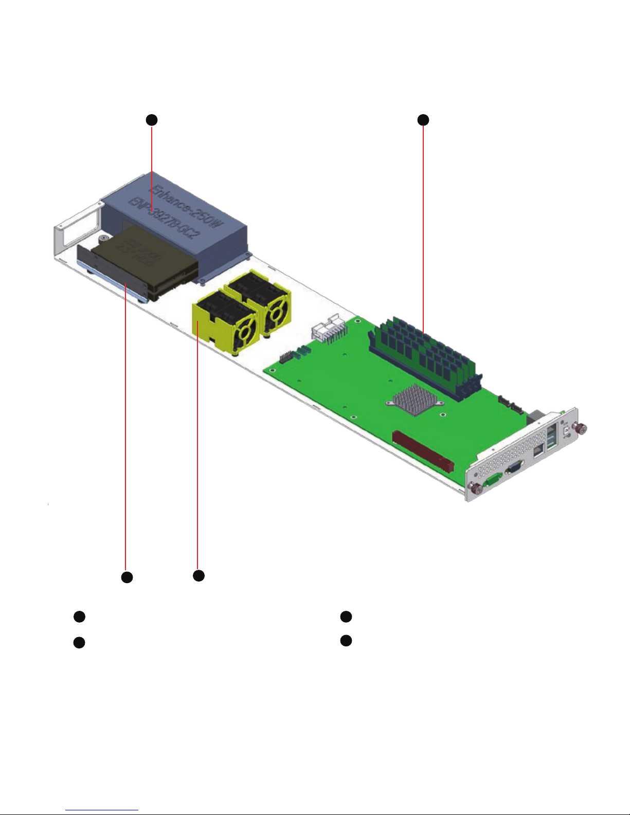
1
3
2
Exhausted Fan
Fan 2.5” HDD
1
3
4
Figure 6 Chassis opened view
1.6 Blade components
2
6 7
4
motherboard
User Manual B410PT
6 7
Chapter 2. System Board and Cable Features
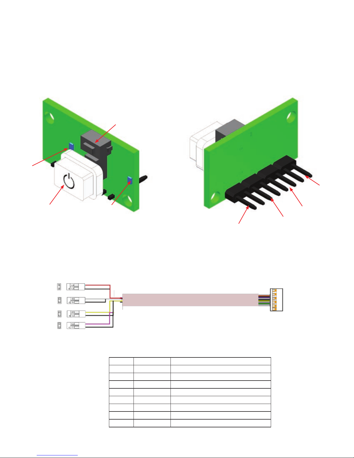
2.1 Front Panel Board (order #16-0123-01A)
The Front Panel Board supports several push buttons and status LEDs to centralize system
control, monitoring, and accessibility to within a common compact design. The following diagram
overviews the board layout and pin assignments for connectivity.
2.1.1 Front Panel Board cable (17-1035-01A)
Power
Switch
HDD ACT
LED
Power
LED
Power
Switch
Power
LED
HDD ACT
LED
Pin Color Signal Name
J2-1 Black Power LED Positive (+)
J2-2 RED Power LED Negative (-)
J3-1 Green Power Switch
J3-2 Orange Power Switch
J4-1 Black Reset Switch
J4-2 Yellow Reset Switch
J5-1 Black HDD LED Positive (+)
J5-2 Purple HDD LED Negative (-)
Table 1 Front Panel I/O cable Pin assignment
J2
J3
J4
J1
Figure 7 Front Panel Board
Figure 8 Front Panel Board
Reset
Switch
Reset
Switch
J5

User Manual B410PT
Chapter 3. Integration Steps
This section provides procedures for installing, removing and replacing components and
assemblies in your Port Townsend blade server
Unless otherwise noted, each procedure assumes the following conditions:
You have read the safety instructions of this user manual. Always follow the in-
structions closely. While working on the system, do not attempt to service the
system except as explained in this guide and elsewhere in TST documentation.
You can install, replace or reinstall a part by performing the removal procedure in
reverse order, unless additional information is provided.
Recommended Tools
Phillips-head screwdriver
Wrist grounding strap
The Power Button on the front panel DOES NOT turn off the AC power, you
MUST unplug the AC power cords
To maintain and ensure regulate compliance, the fully integrated system should be test-
ed, certied and/or documented to illustrate compliance to the regional regulations and
laws for where the product will be sold. The peripherals such as hard disk drive, memory
and add-in-cards chosen for integration should have individual regulatory
approvals.
10 11

User Manual B410PT
10 11
3.1 Removing the server blade
WARNING: DO NOT USE TOP THUMB SCREW TO LIFT CHASSIS! These thumb
screws are used only to install and remove the blade only!
Loosen the two thumbscrews that secure the
blade to the chassis. If the thumbscrew is too
tight, use the Philip-head screw drivers to untight-
en it as shwon in gure shown
Slide the blade forward and grasp the cover at
both ends.
Ensure that the work surface is at and clean to
prevent scratching the computer cover
1
2
3
3.1.1 Removing the blade
Figure 14 Indentify the blade you want to remove
Figure 15 loosen the thumbscrews
Figure 16 Slide out the blade
WARNING: To reduce the risk of personal injury from hot surfaces, allow the drives
and the internal system components to cool before touching them.
User Manual B410PT
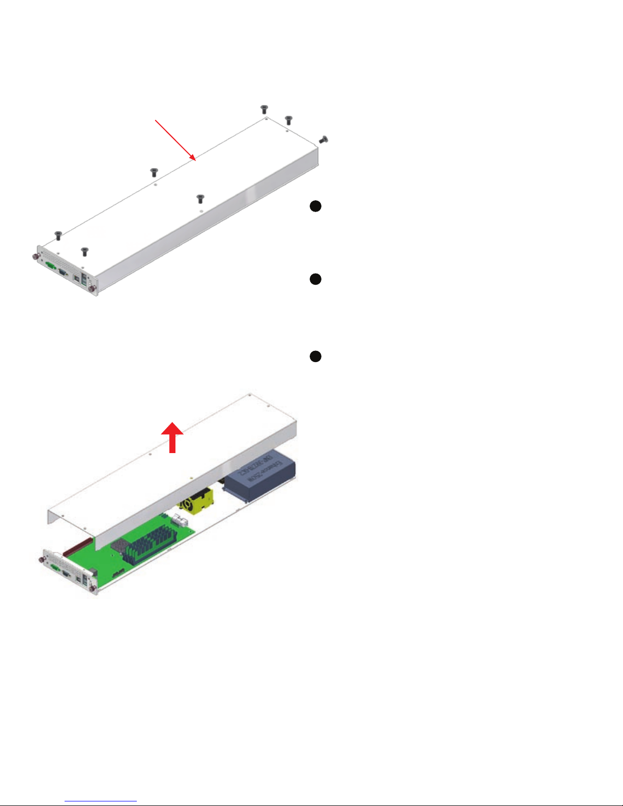
3.2 Removing the top cover
Ensure that the work surface is at and clean to
prevent scratching the computer cover
1
3Pull the front cover up and put it aside and away
from the immediate working area
#6-32 FH screws (order #09-1002-01A)
Untigthen two at head #6-32 6mm screws of the
HDD cover as shown on the gure.
2
Figure 17 Remove the HDD top cover
Figure 18 Remove the blade top cover
12 13
Table of contents


