Tsubaki TKP91 User manual
1/14
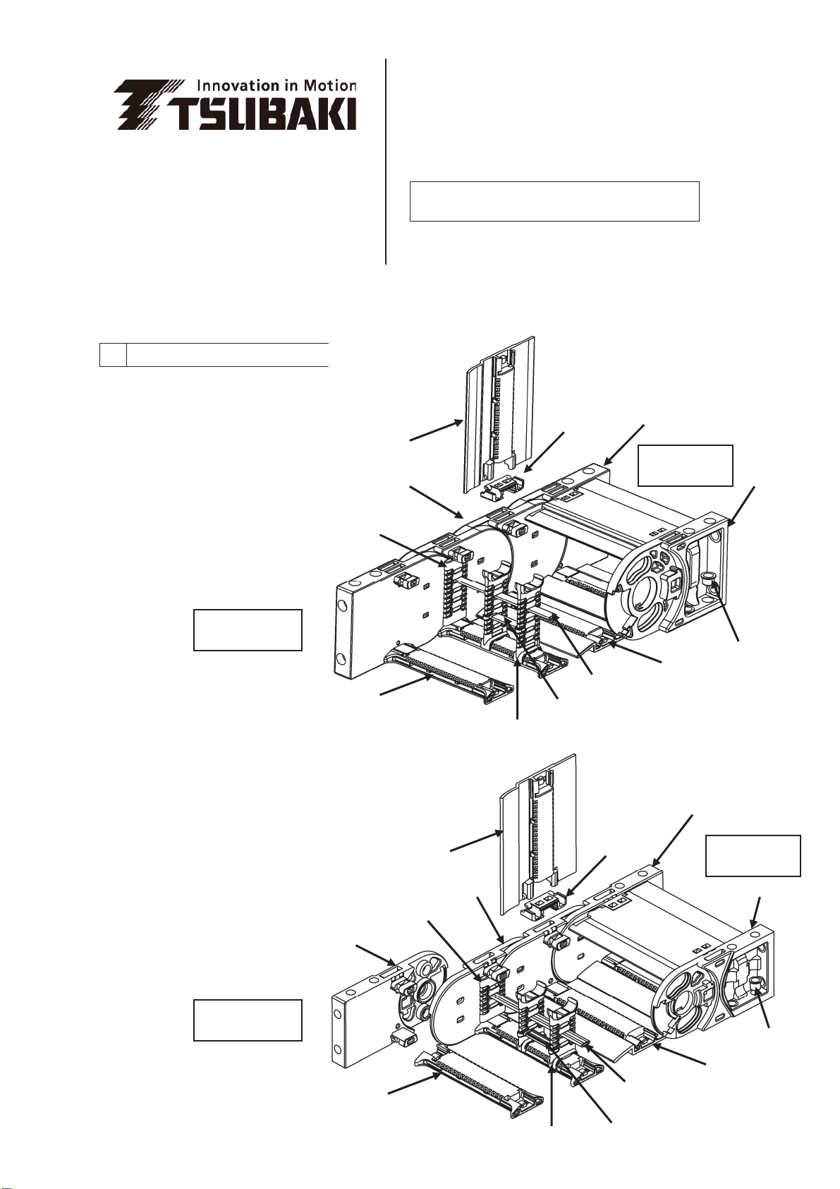
1Construction/Part Names
㩷㩷TKP/TKC 91 H80 Types
㩷TKP/TKC 91 H56 Types
Thank you for your purchase of a Tsubaki plastic Cableveyor.
This instruction manual covers points from delivery to installation, and should be read
before beginning work.
Tsubaki
TKP/TKC91
Plastic Cableveyor
Instruction Manual
Closed-type Arm Hin
g
e
Link
Bracket
(
A
)
Bracket
(
B
)
Bush
Lock Sta
y
Open-type Arm
Vertical Divider
(usable either side)
V
ertical Divide
r
Horizontal Divider
(
DSA t
yp
e
)
Horizontal Divider
(DSB type)
Closed-type Arm Hin
g
e
Link
Bracket
(
B
)
Bracket
(
D
)
Bracket
(
C
)
Bush
Lock Sta
y
Open-type Arm
Horizontal Divider
(
DSA t
yp
e
)
Horizontal Divider
(
DSB t
yp
e
)
Vertical Divider
Vertical Divider
(
usable either side
)
Moving End
Moving End
Fixed End
Fixed End
2/14
2 Before Assembly
1) Use only a flat-head screwdriver with a 4.5mm head and a plastic hammer.
A screwdriver with a larger head will not fit into the release hole and can damage parts.
2) This product can be easily assembled and disassembled. If parts are difficult to insert they may be misaligned.
Do not pound in. Check positioning and realign.
3) There is no need to tap the screwdriver handle with a hammer. Doing so may damage parts.
4) Wear gloves, safety glasses, safety shoes, and other protective gear as appropriate when working.
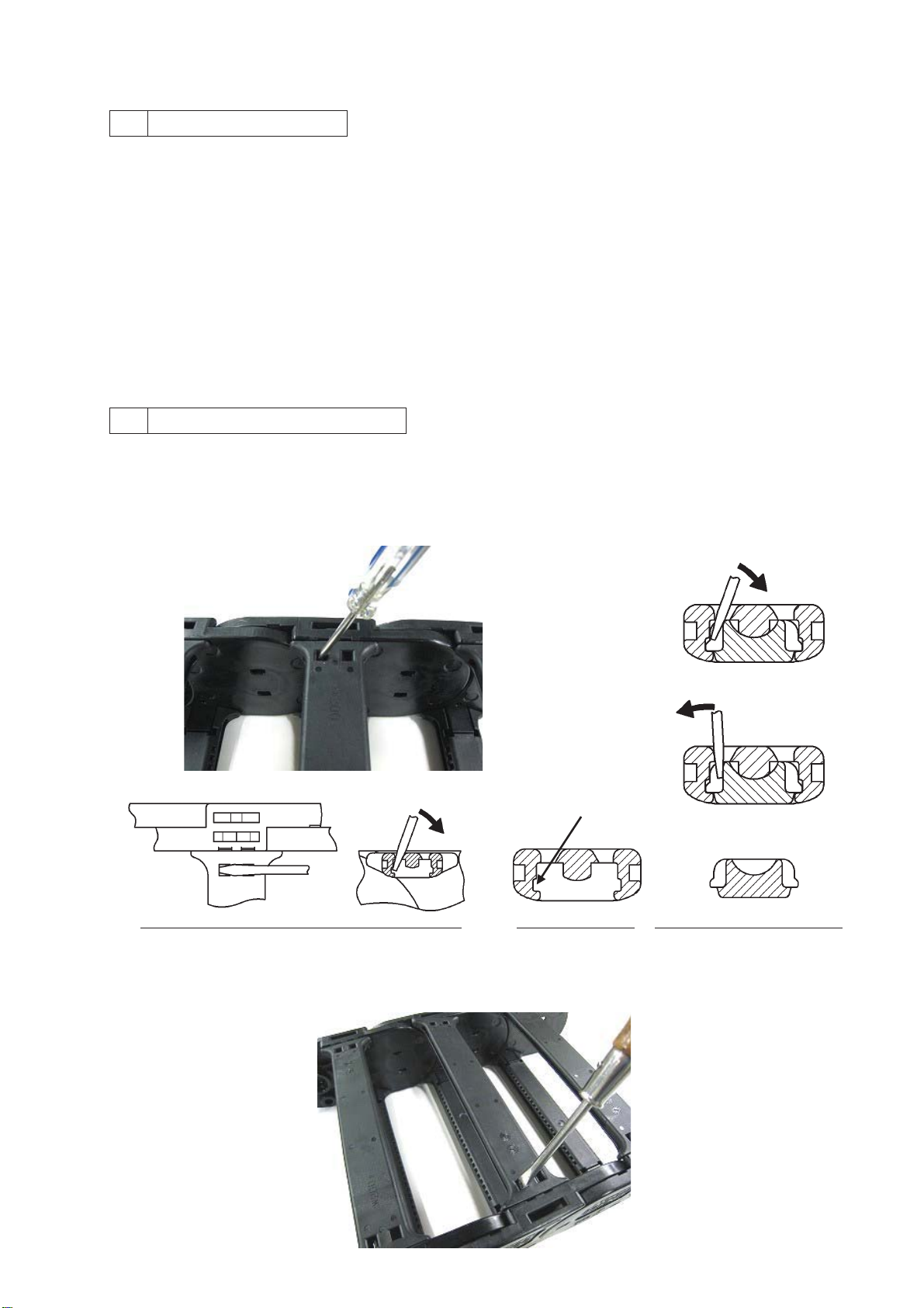
3 Arm Types and Removal
*All TKP91 (open type) arms are interchangeable (Caution!)
1) Hold down the arm with your hand and insert a Cross-section of arm and link
screwdriver about 7mm into the release hole and twist Undo the hook as shown below.
as shown in the diagram
㩷㩷㩷㩷㩷㩷㩷㩷㩷㩷㩷㩷㩷㩷㩷㩷㩷㩷㩷㩷㩷㩷㩷㩷㩷㩷㩷㩷㩷㩷㩷㩷㩷㩷㩷㩷㩷㩷㩷㩷㩷㩷㩷㩷㩷㩷䂾
䂾㩷
Correct
㩷㩷㩷㩷㩷㩷㩷㩷㩷㩷㩷㩷㩷㩷㩷㩷㩷㩷㩷㩷㩷㩷㩷㩷㩷㩷㩷㩷㩷㩷㩷㩷㩷㩷㩷㩷㩷㩷㩷㩷㩷㩷㩷㩷㩷㩷 ×
㩷
Bad
㩷㩷㩷㩷㩷㩷㩷㩷㩷㩷㩷㩷㩷㩷㩷㩷㩷㩷㩷㩷㩷㩷㩷㩷㩷㩷㩷㩷㩷㩷㩷㩷㩷㩷㩷㩷㩷㩷㩷㩷㩷
Hook
㩷㩷㩷Upper and cross-sectional view (link side omitted)㩷㩷㩷㩷 Arm cross-section㩷㩷Cross-section of link fastener
2) Once you have undone the hook and one side of the arm has lifted, undo the hook on the opposite side and
twist and lift up to remove arm.

3/14
*For TKC91 (closed type), the arms (with hinge) and lock stays are not interchangeable.
㩷䊶
䊶
Removing an arm on the end
1) The arm has a hook on one end and a hinge (separate part) on the other, as shown below. First, insert a
screwdriver about 7mm into the release hole on the flat side of the hook end (the left side in this diagram) and
twist to lift the arm.
㩷㩷㩷㩷㩷㩷㩷㩷㩷㩷㩷㩷㩷㩷㩷㩷㩷㩷㩷㩷㩷㩷㩷㩷㩷㩷㩷㩷㩷㩷㩷㩷㩷㩷㩷㩷㩷㩷㩷㩷㩷㩷㩷㩷㩷㩷Flat hole side
2) Insert fingers into the space under the lifted arm and lift and hold up. Next, insert the screwdriver slightly
between the groove on the top of the link and the underside of the arm and pull the screwdriver down to
release the hook.
3) Hold the end of the arm and using the hinge side as a base push down while twisting to lift arm up.
To remove just the arm, pull straight up with the arm in a standing position to remove. It will pull out easily,
leaving only the hinge behind.
4) To remove the hinge remaining on the link, insert a screwdriver into
one of the two release holes and twist.

4/14
㩷䊶
䊶
Removing an arm in the center
1) Insert a screwdriver about 7mm into the release hole on the flat arm end (the left side in this diagram) and
twist to lift arm. This may release the hook side at the same time.
㩷㩷㩷㩷㩷㩷㩷㩷㩷㩷㩷㩷㩷㩷㩷㩷㩷㩷㩷㩷㩷㩷㩷㩷㩷㩷㩷㩷㩷㩷㩷㩷㩷㩷㩷㩷㩷㩷㩷㩷㩷㩷㩷㩷㩷㩷㩷Flat End
2) If the hook side does not release, insert a screwdriver about 7mm into the release hole on the flat side of the
arm on the opposite side (the left side in this diagram) and twist to lift arm.
3) Lift up the lifted side fully and twist to remove arm.

5/14
㩷䊶
䊶
Removing the lock stay
1) Both sides of the lock stay have the same hook construction. Insert a screwdriver about 7mm into the removal
hole on the flat side of the arm (left side in this diagram) and twist to raise lock stay end.
㩷㩷㩷㩷㩷㩷㩷㩷㩷㩷㩷㩷㩷㩷㩷㩷㩷㩷㩷㩷㩷㩷㩷㩷㩷㩷㩷㩷㩷㩷㩷㩷㩷㩷㩷㩷㩷㩷㩷㩷㩷㩷㩷㩷㩷㩷㩷㩷㩷㩷Flat side
2) Insert fingers into the lifted space in the lock stay and lift and hold up. Insert a screwdriver into the release hole
on the flat side on the other end. Unhook the side and twist the entire arm while lifting up to remove.
4 Arm Types and Assembly
*TKP91 (open type) arms are interchangeable
1) Ensure the link cannot move. Align an arm parallel with the installation area of the link and lightly tap with a
plastic hammer from directly above as indicated by the arrows below to attach. Links will not attach if
misaligned. Forcing links into place may damage them. Refer to the notes below if links are difficult to attach.
Once the link is securely attached, repeat these steps on the other side.
㩷㩷㩷㩷㩷㩷㩷㩷㩷㩷㩷㩷㩷㩷㩷㩷㩷㩷㩷㩷㩷㩷㩷㩷㩷㩷㩷㩷㩷㩷㩷㩷㩷㩷㩷㩷㩷㩷㩷㩷㩷Note: Lay against link end and keep parallel.
㩷㩷㩷㩷㩷㩷㩷㩷㩷㩷㩷㩷㩷㩷㩷㩷㩷㩷㩷㩷㩷㩷㩷㩷㩷㩷㩷㩷㩷㩷㩷㩷㩷㩷㩷㩷㩷㩷㩷㩷㩷㩷㩷 Not tilted㩷㩷㩷 㩷㩷㩷㩷Parallel
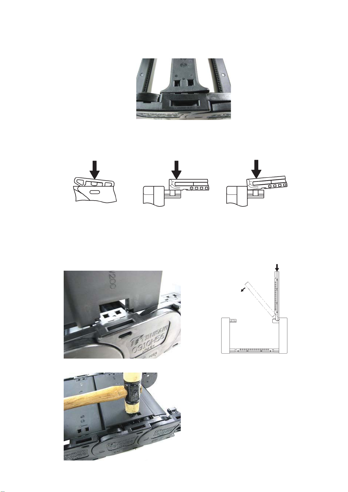
6/14
2) If the arm isn’t securely attached then it will be lifted like shown in the photo below. Ensure the arm is attached
securely before use.
Note: You will not be able to attach the arms if they are:
㩷㩷㩷㩷㩷㩷㩷㩷㽲 Tilted laterally㩷㩷㩷㩷㩷 㽳 Not flush with the link end㩷㩷㩷㩷㽴 Attachment area not parallel
*TKC91 (closed type) arm
1) Closed-type arms consist of the arm itself and two hinges. If there are only hinges in the link, then hold the
arm vertically on the hinge side and press into the hinge to secure it.
Once secure, press down on the link, twist slowly, and let fall.
2) While pressing down the center of the arm, lightly tap the hook area on the hinge and non-hinged side to close.
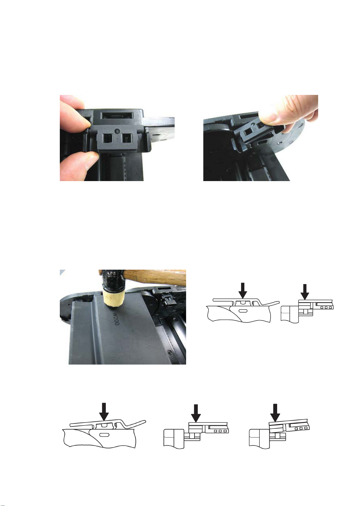
7/14
㩷㩷Note: Attach the hinge unit to the link installation area as follows.
㩷㩷㩷㽲 If using a plastic hammer 㽳 If using your hands
㩷㩷㩷㩷 Lay parallel in the mounting area and tap Lay hinge diagonally and twist with hook
directly from above. attached on one side.
㩷㩷㩷Note: The part is small, so tap until it is firmly attached.
*TKC91 (closed type) lock stay
1) Lay a lock stay parallel to the installation area of a secured link. Then, tap lightly from directly above as
indicated by the arrows below to attach. Lock stays will not insert if they are misaligned. Forcing lock stays into
place may damage them. See cautions below if it is difficult to attach the stay.
Once the lock stay is firmly inserted follow these directions for the other side to attach.
Lay against link end and keep parallel.
㩷㩷Note: You will not be able to attach the stay if they are:
㩷㩷㩷㩷㩷㩷㩷㩷㽲 Tilted laterally㩷㩷㩷㩷㩷㩷㩷㩷㩷㩷㽳 Not flush with the link end㩷㩷㩷㩷㽴 Attachment area not parallel
8/14
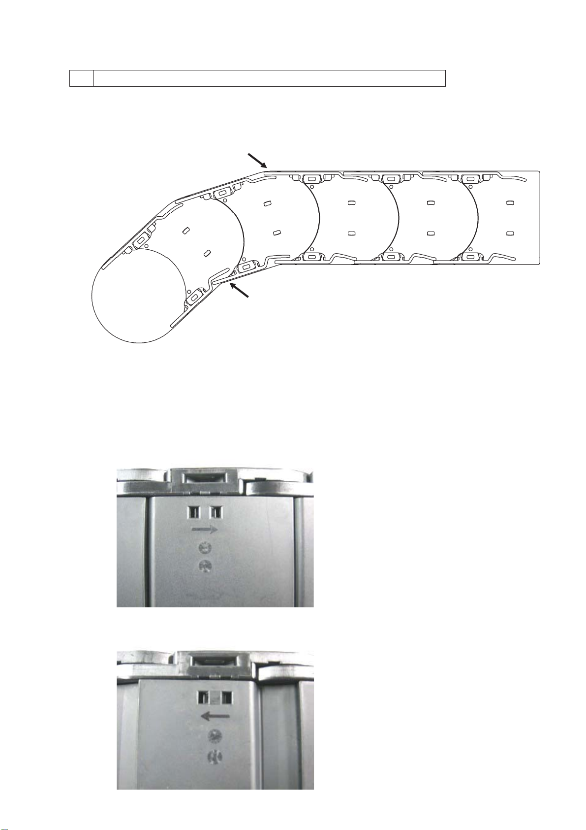
5 Closed-type Arm Direction and Assembly
1) For closed-type Cableveyors, either the arms on the outer circumference or the lock stays on the inner
circumference will overlap each other. Attached dust and other foreign matter can enter the Cableveyor
interior unless installed as shown below.
Overlap㩷㩷㩷㩷Moving end bracket side (from above) 㹢Attach to equipment
㩷㩷㩷㩷㩷㩷㩷㩷㩷㩷㩷㩷㩷㩷㩷㩷㩷㩷㩷㩷
Note: Install as shown in the diagram.
2) There is an assembly direction for arms and lock stays. An arrow is stamped onto the part – please ensure
that all parts face the same direction when installing.
Keep in mind when attaching to the equipment that all arrows point in the direction of the fixed end bracket.
㩷㩷㩷㩷㩷Arm
㩷㩷㩷㩷㩷Lock Stay
Overlap
9/14
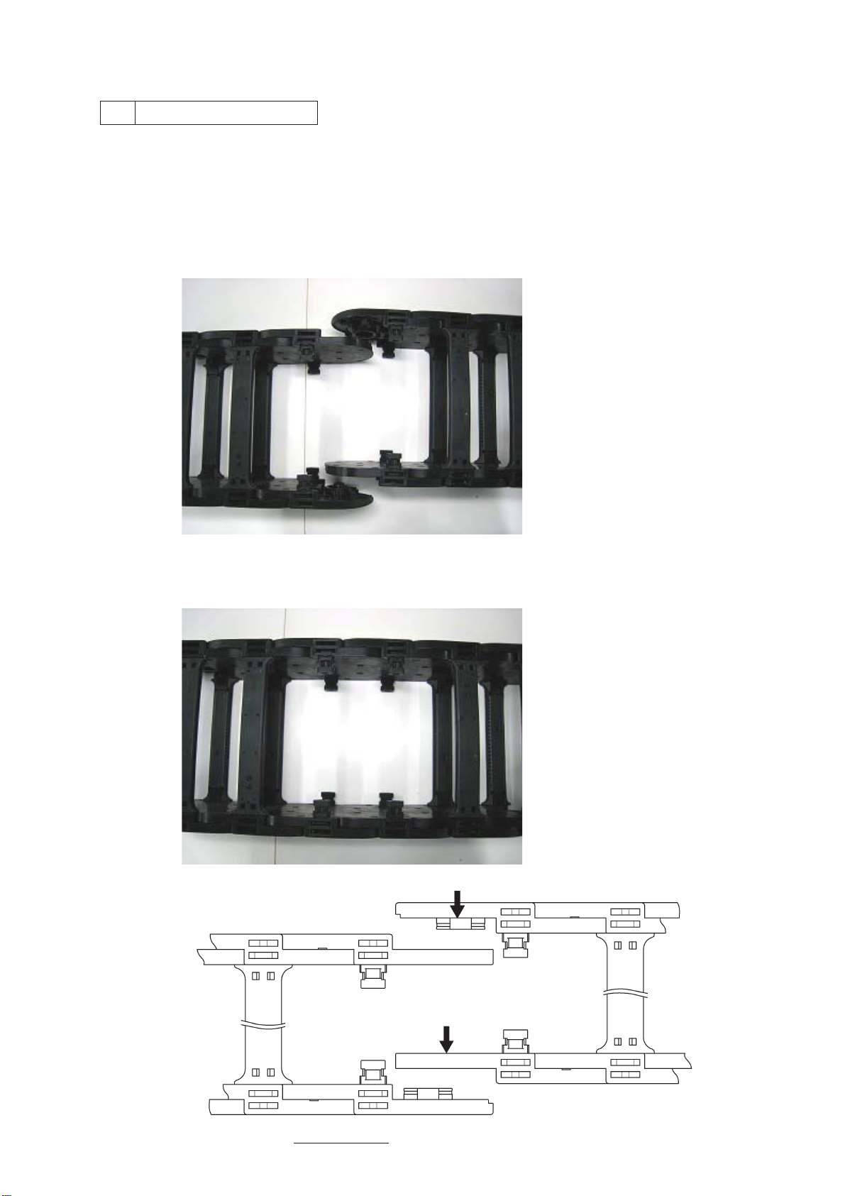
6 Connecting Links
Tsubaki plastic Cableveyors may be packaged and shipped disassembled in set unit lengths. Use the following
method to connect the Cableveyor to the desired length.
*91H80 (inner height 80mm) Left and right links are the same.
1) To connect two disassembled Cableveyors, remove the arms and lock stays (if present) on the links of each
end to be connected.
2) Align the links to be connected and press together laterally. Links will fit together with a loose snap fit.
Then, push together firmly by hand or tap lightly with a plastic hammer until the link ends touch and they are
firmly connected. Once joined, attach the arms.
㩷㩷㩷㩷㩷㩷㩷㩷㩷㩷㩷㩷㩷㩷㩷㩷㩷㩷㩷㩷㩷*Open type arm

10/14
*91H56 (inner height 56mm) Left and right links are different and cannot be interchanged.
1) To connect two disassembled Cableveyors, remove the arms and lock stays on the two links at each end to
be connected.
2) Align the links to be connected and press together along the direction of pitch. Links will fit together with a
loose snap fit.
Then, push together firmly by hand or tap lightly with a plastic hammer until the link ends touch and they are
firmly connected. Once joined, attach the arms.
*Open type arm
This manual suits for next models
1
Table of contents
Popular Network Hardware manuals by other brands

Matrix Switch Corporation
Matrix Switch Corporation MSC-HD161DEL product manual

B&B Electronics
B&B Electronics ZXT9-IO-222R2 product manual

Yudor
Yudor YDS-16 user manual

D-Link
D-Link ShareCenter DNS-320L datasheet

Samsung
Samsung ES1642dc Hardware user manual

Honeywell Home
Honeywell Home LTEM-PV Installation and setup guide


