- 2 -
● Use the product described in this instruction manual by obser ing safety-related
laws and regulations such as Ordinance on Industrial Safety and Health.
● Obser e the following during the installation, remo al, or maintenance/inspection of
the product:
(1) Turn off the power switch.
(2) Do not go below any equipment which may fall and drop.
(3) Secure mo ing parts of the equipment so that they will not mo e unexpectedly.
(4) Wear appropriate clothing and protecti e gear for the work.
● Before starting trial operation or regular inspection, be sure to confirm the
operation so that the Shock Monitor properly works as a protection de ice.
● The Shock Monitor main unit is subject to conditions when it is used for a megger
test. Follow the instruction in the instruction manual.
● Do not work while the line is li e. Be sure to turn off the power before starting work.
Otherwise, an electric shock may result.
Otherwise, an electric shock may result.Otherwise, an electric shock may result.
Otherwise, an electric shock may result.
● The wiring, energization/operation, and maintenance/inspection of the Shock
Monitor must be done by an engineer with expert knowledge.
Otherwise, an electric sh
Otherwise, an electric shOtherwise, an electric sh
Otherwise, an electric shock, injury, or fire may result.
ock, injury, or fire may result.ock, injury, or fire may result.
ock, injury, or fire may result.
● Be sure to ground Terminal E of the Shock Monitor.
Otherwise
OtherwiseOtherwise
Otherwise,
,,
, an accident may result.
an accident may result. an accident may result.
an accident may result.
● When using a 400 VAC motor power supply, ensure that the Shock Monitor unit and
400 V resistor are connected properly.
Otherwise, an
Otherwise, an Otherwise, an
Otherwise, an electric shock or fire may result.
electric shock or fire may result.electric shock or fire may result.
electric shock or fire may result.
● Ensure that this instruction manual is deli ered to the end users.
Also, let the end users carefully read the manual before using the Shock Monitor to
ensure correct use.
● If you do not ha e the instruction manual, contact your TEM dealer or a TEM sales
office and request a copy by specifying the product name, model number, etc.
● Do not disassemble the product or make additional work for modification.
● This product contains se eral consumable parts (electrolyti
se eral consumable parts (electrolytise eral consumable parts (electrolyti
se eral consumable parts (electrolytic capacitor, relay, etc.)
c capacitor, relay, etc.)c capacitor, relay, etc.)
c capacitor, relay, etc.).
Check functions and operation periodically according to the instruction manual. If
any malfunction is found, contact your dealer for repair.
● Do not use the Shock Monitor in an atmosphere where any corrosi e gas exists.
Sulfidizing gases (SO2, H2S), in particular, cause corrosion of copper and copper
alloy used in the printed circuit boards and components, resulting in breakdowns.
● Do not allow the entry of foreign matter such as lint, paper pieces, woodchips, dust,
or metal chips into the Shock Monitor.
● Clean off dirt periodically because it may cause o erheating of the product or fire.
● When discarding the product, dispose it as industrial waste.
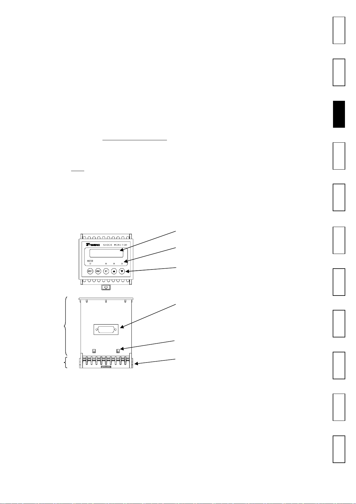
Contents
/Names
Safety
Safety
Safety
Safety
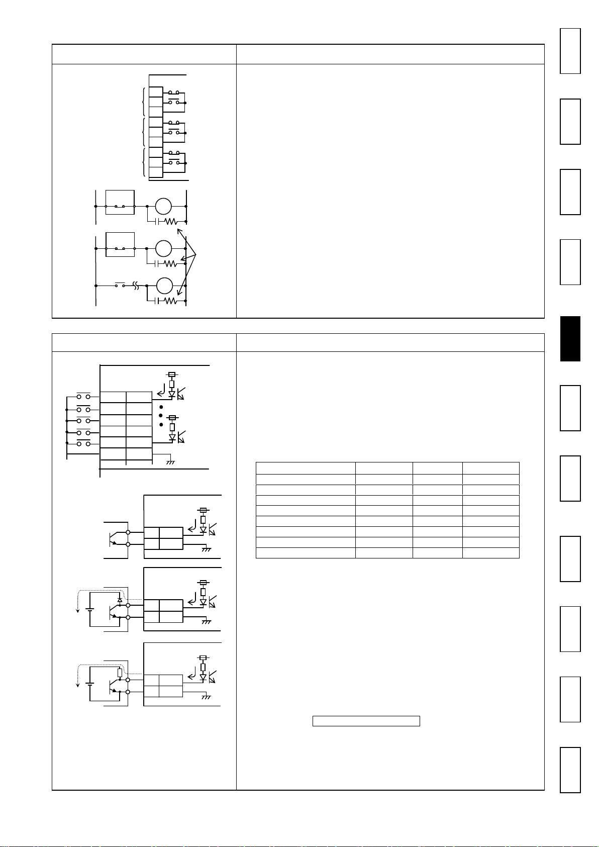
/Wiri ng
Term inals
Connec t ion
Operation
/Inspection
S p ec i fi c a t io n s
Dimens ions
Warranty
WARNING
CAUTION